EP1422437B1 - Schwingungsdämpfende Vorrichtung für Antriebswelle eines Kraftfahrzeuges - Google Patents
Schwingungsdämpfende Vorrichtung für Antriebswelle eines Kraftfahrzeuges Download PDFInfo
- Publication number
- EP1422437B1 EP1422437B1 EP03292881A EP03292881A EP1422437B1 EP 1422437 B1 EP1422437 B1 EP 1422437B1 EP 03292881 A EP03292881 A EP 03292881A EP 03292881 A EP03292881 A EP 03292881A EP 1422437 B1 EP1422437 B1 EP 1422437B1
- Authority
- EP
- European Patent Office
- Prior art keywords
- mass
- shaft
- ring
- damper
- drive shaft
- Prior art date
- Legal status (The legal status is an assumption and is not a legal conclusion. Google has not performed a legal analysis and makes no representation as to the accuracy of the status listed.)
- Expired - Lifetime
Links
- 239000013536 elastomeric material Substances 0.000 claims description 3
- 230000000694 effects Effects 0.000 claims 1
- 230000002035 prolonged effect Effects 0.000 claims 1
- 238000013016 damping Methods 0.000 description 13
- 229910052751 metal Inorganic materials 0.000 description 2
- 239000002184 metal Substances 0.000 description 2
- 239000006096 absorbing agent Substances 0.000 description 1
- 238000010521 absorption reaction Methods 0.000 description 1
- 229910045601 alloy Inorganic materials 0.000 description 1
- 239000000956 alloy Substances 0.000 description 1
- 238000010276 construction Methods 0.000 description 1
- 238000006073 displacement reaction Methods 0.000 description 1
- 238000009434 installation Methods 0.000 description 1
- 238000004519 manufacturing process Methods 0.000 description 1
- 239000000463 material Substances 0.000 description 1
- 150000002739 metals Chemical class 0.000 description 1
- 238000000465 moulding Methods 0.000 description 1
- 230000035939 shock Effects 0.000 description 1
Images


Classifications
-
- F—MECHANICAL ENGINEERING; LIGHTING; HEATING; WEAPONS; BLASTING
- F16—ENGINEERING ELEMENTS AND UNITS; GENERAL MEASURES FOR PRODUCING AND MAINTAINING EFFECTIVE FUNCTIONING OF MACHINES OR INSTALLATIONS; THERMAL INSULATION IN GENERAL
- F16F—SPRINGS; SHOCK-ABSORBERS; MEANS FOR DAMPING VIBRATION
- F16F15/00—Suppression of vibrations in systems; Means or arrangements for avoiding or reducing out-of-balance forces, e.g. due to motion
- F16F15/10—Suppression of vibrations in rotating systems by making use of members moving with the system
- F16F15/14—Suppression of vibrations in rotating systems by making use of members moving with the system using masses freely rotating with the system, i.e. uninvolved in transmitting driveline torque, e.g. rotative dynamic dampers
- F16F15/1407—Suppression of vibrations in rotating systems by making use of members moving with the system using masses freely rotating with the system, i.e. uninvolved in transmitting driveline torque, e.g. rotative dynamic dampers the rotation being limited with respect to the driving means
- F16F15/1414—Masses driven by elastic elements
- F16F15/1435—Elastomeric springs, i.e. made of plastic or rubber
- F16F15/1442—Elastomeric springs, i.e. made of plastic or rubber with a single mass
Definitions
- Dynamic dampers are often installed or inserted directly on rotating shafts.
- the dynamic damper is intended to generate a predetermined vibration frequency adjusted to the dominant frequency of the harmful vibrations excited.
- the dynamic damping device converts or transfers vibratory energy from the rotary drive shaft to the dynamic resonance damping device and optionally absorbs vibratory energy from the rotating shaft.
- the damping device attempts to eliminate or cancel the vibrations that are induced or caused by the rotary drive shaft during normal operation of the vehicle drive train.
- the dynamic damping device must appropriately generate the range of specific harmonic frequency that is required to counterbalance unwanted vibration of the rotary drive shaft.
- a dynamic damping device which comprises a pair of ring-shaped fasteners spaced from each other at a predetermined interval. This device is inserted and carried by the rotary drive shaft. A mass is disposed between the pair of fasteners shaped ring. A pair of connecting members is then provided for connecting the ends of the fasteners to the end of the mass.
- the damping device of Hamada et al requires individual metal clamps to be added on each side and ring-shaped fasteners to effectively secure the dynamic damping device on the shaft. rotating lead.
- the ring-shaped fasteners are spaced from each other from the mass not only in the vertical direction but also in the horizontal direction increasing the overall size of the assembly.
- Patent Abstracts of Japan, Vol. 014, No. 527 (M-1050) JP 02221731 A discloses a vibration damping device for rotating shaft, comprising a cylindrical mass, an elastic sleeve connecting the ring to the shaft by means of two elastic rings, the first ring having a cylindrical shape and extending longitudinally from a first end of the mass to fix the device to the shaft, possibly with a clamp, the second ring being housed under the mass in the vicinity of its second end and subjected to compressive deformation.
- the elasticity constant of the first ring is lower than that of the second ring.
- the invention is defined by the features of claim 1.
- the invention relates to a vibration absorbing and damping device for a rotary drive shaft of a motor vehicle comprising: a mass of generally cylindrical shape having an inner surface and an outer surface, an elastic member made of an elastomeric material such as rubber or the like, this elastic member connecting the mass to the shaft by means of two elastic rings, the first elastic ring having a cylindrical shape and extending longitudinally from one of the ends of the mass, to fix the device to the shaft, and optionally comprising a tightening belt for securing, the second elastic ring being housed under the mass in the vicinity of the second end of the mass, extending radially with respect to the shaft and being subjected to a compressive deformation between the mass and the shaft.
- a dynamic damping device allows changes in the harmonic frequency range by increasing or reducing the length or by changing the shape of the elastic ring housed between the mass and the drive shaft.
- the second elastic ring is subjected to compressive deformation over at least a portion of its length only.
- the second elastic ring extends beyond the end of the mass, only part of the ring being subjected to a compressive deformation, that is to say that between the mass and the rotary drive shaft.
- the second ring is also divided into equidistant portions.
- the present invention also provides a dynamic damper that can be attached to a rotating shaft using either a belt tensioned on the first elastic ring or no belt by adjusting the shape and diameter of the first elastic ring to increase the resistance to axial and rotary movement once the device is mounted on the shaft.
- the total length of the device is thus advantageously reduced by eliminating a ring-shaped connection member between the mass and the shaft.
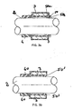
- the attenuation and absorption device or dynamic damper 1 according to the invention is mounted on a rotary shaft 2 such as a drive shaft of a vehicle engine.
- the dynamic damper 1 comprises a mass 3 in the form of a cylinder.
- This mass 3 has an inside diameter greater than the outside diameter of the rotary shaft 2 on which the dynamic damper 1 must be mounted.
- the cylindrical mass 3 may be made of various metals, alloys and other materials offering a density sufficient to obtain mass weight required to damp the vibrations of the rotary drive shaft 2.
- the damper 1 further comprises an elastic member made of an elastomeric material such as rubber or the like, this elastic member connecting the mass 3 to the shaft 2 by means of two elastic rings 4, 40 and 5, 50, 500 .
- the first elastic ring 4, 40 has a cylindrical shape and extends in a longitudinal direction from a first end of the mass 3, to fix the device to the shaft 2.
- This fixing ring 4, 40 has a diameter inside lower than the outer diameter of the rotary shaft 2 so as to allow a safe establishment of the dynamic damper 1 on the rotary shaft 2 and prevent movement of said damper 1 along the rotary shaft 2.
- the second elastic ring 5, 50, 500 is housed under the mass 3 in the vicinity of the second end of the mass 3, on the opposite side to the first ring 4, 40 and extends radially with respect to the shaft 2. This ring 5, 50, 500 is subjected to a compressive deformation between the mass 3 and the shaft 2.
- the mass 3 is preferably inserted by molding with the rings 4, 40; 5, 50, 500.
- a clamping collar 6 is put in place to guarantee an even more secure fastening of the damper 1 on the rotary shaft 2.
- the variant of the shock absorber that is presented comprises an elastic ring 40 whose shape is tapered inwards, which makes it possible to increase the resistance to displacement of the damper 1 without it being necessary to in this case use a clamp. This saves time during installation and is therefore economically more advantageous despite the fact that it is necessary to mount the device in a determined direction D to avoid any risk of deformation during assembly.
- the second elastic ring extending below the mass 3, between the mass 3 and the drive shaft 2 can be modified in length and shape for different applications.
- the elastic ring 50 has a part 50a compressed between the shaft 2 and the mass 3 but also a part 50b which is also extended axially outside the mass 3. This increases the resistance to moving the damper along the rotary shaft 2, but this also makes it possible to adjust the damper to the required resonance frequency.
- this elastic ring 50 has an inclined face, which improves the mounting of the device in the direction D when the first elastic ring 40 is as shown in FIG. 2a.
- the second elastic ring is divided into equidistant portions 500, which makes it possible to modify the zone compressed between the shaft 2 and the mass 3.
- the number of spaces 7 formed between the ring portions is adjustable to set the damper to the required resonance frequency. This allows the damper to be adjusted if this can not be done by changing the length of the second ring.
- FIGS. 5a and 5b show an embodiment according to the invention according to which the second elastic ring is divided into six equidistant portions 500 and a portion 500a of said ring also extends outwardly beyond the mass 3.
Landscapes
- Engineering & Computer Science (AREA)
- General Engineering & Computer Science (AREA)
- Physics & Mathematics (AREA)
- Acoustics & Sound (AREA)
- Aviation & Aerospace Engineering (AREA)
- Mechanical Engineering (AREA)
- Motor Power Transmission Devices (AREA)
- Vibration Prevention Devices (AREA)
- Shafts, Cranks, Connecting Bars, And Related Bearings (AREA)
- Arrangement Or Mounting Of Propulsion Units For Vehicles (AREA)
Claims (1)
- Schwingungsaufnehmende und schwingungsdämpfende Vorrichtung für die Antriebswelle (2) eines Kraftfahrzeuges mit- einer im wesentlichen zylindrischen Masse (3) mit einer Innenfläche und einer Außenfläche,- einem elastischen Element aus einem Elastomerwerkstoff wie Gummi oder einem ähnlichen Werkstoff, das die Masse (3) über zwei elastische Ringe (40; 500) mit der Antriebswelle (2) verbindet,- wobei der erste elastische Ring (40) eine zylindrische Form aufweist und sich ausgehend von einem ersten Ende der Masse (3) deren Längsrichtung erstreckt, um die Vorrichtung an der Antriebswelle (2) zu befestigen, und gegebenenfalls eine Klemmschelle (6) zur Sicherung der Befestigung aufweist,- wobei der zweite elastische Ring (500) unter der Masse (3) in der Nähe des zweiten Endes der Masse (3) sitzt und sich radial zu der Antriebswelle (2) erstreckt und ein Teil (500) aufweist, das zwischen der Antriebswelle (2) und der Masse (3) zusammendrückbar ist, sowie ein Teil (500a), das außen an der Masse (3) axial verlängert ist,dadurch gekennzeichnet, dass das Teil des zweiten Rings, das zusammendrückbar ist, in abstandsgleiche Abschnitte (500) unterteilt ist.
Applications Claiming Priority (2)
| Application Number | Priority Date | Filing Date | Title |
|---|---|---|---|
| FR0214493A FR2847320B1 (fr) | 2002-11-19 | 2002-11-19 | Dispositif d'absorption et d'attenuation de vibrations pour arbre d'entrainement dans un vehicule |
| FR0214493 | 2002-11-19 |
Publications (2)
| Publication Number | Publication Date |
|---|---|
| EP1422437A1 EP1422437A1 (de) | 2004-05-26 |
| EP1422437B1 true EP1422437B1 (de) | 2007-05-23 |
Family
ID=32187746
Family Applications (1)
| Application Number | Title | Priority Date | Filing Date |
|---|---|---|---|
| EP03292881A Expired - Lifetime EP1422437B1 (de) | 2002-11-19 | 2003-11-19 | Schwingungsdämpfende Vorrichtung für Antriebswelle eines Kraftfahrzeuges |
Country Status (4)
| Country | Link |
|---|---|
| EP (1) | EP1422437B1 (de) |
| AT (1) | ATE363038T1 (de) |
| DE (1) | DE60313935D1 (de) |
| FR (1) | FR2847320B1 (de) |
Families Citing this family (3)
| Publication number | Priority date | Publication date | Assignee | Title |
|---|---|---|---|---|
| DE102005021098B3 (de) * | 2005-05-06 | 2006-08-31 | SGF Süddeutsche Gelenkscheibenfabrik GmbH & Co KG | Schwingungstilger, insbesondere zur Anbringung an einem Getriebeschalthebel eines Kraftfahrzeugs |
| KR20130048816A (ko) * | 2011-11-03 | 2013-05-13 | 삼성전자주식회사 | 배관진동 저감용 댐퍼 |
| CN105370794B (zh) * | 2015-12-18 | 2018-01-16 | 环宇东海橡塑(天津)有限公司 | 双频阻尼器 |
Family Cites Families (3)
| Publication number | Priority date | Publication date | Assignee | Title |
|---|---|---|---|---|
| JPH0747978B2 (ja) * | 1989-02-23 | 1995-05-24 | 東海ゴム工業株式会社 | ダイナミックダンパ |
| JPH0337450A (ja) * | 1989-06-30 | 1991-02-18 | Kinugawa Rubber Ind Co Ltd | ダイナミックダンパ |
| US5660256A (en) * | 1995-09-22 | 1997-08-26 | Gkn Automotive, Inc. | Dynamic damper |
-
2002
- 2002-11-19 FR FR0214493A patent/FR2847320B1/fr not_active Expired - Fee Related
-
2003
- 2003-11-19 EP EP03292881A patent/EP1422437B1/de not_active Expired - Lifetime
- 2003-11-19 DE DE60313935T patent/DE60313935D1/de not_active Expired - Lifetime
- 2003-11-19 AT AT03292881T patent/ATE363038T1/de not_active IP Right Cessation
Also Published As
| Publication number | Publication date |
|---|---|
| ATE363038T1 (de) | 2007-06-15 |
| DE60313935D1 (de) | 2007-07-05 |
| FR2847320A1 (fr) | 2004-05-21 |
| FR2847320B1 (fr) | 2006-06-09 |
| EP1422437A1 (de) | 2004-05-26 |
Similar Documents
| Publication | Publication Date | Title |
|---|---|---|
| CA2956917C (fr) | Atterrisseur pour aeronef comportant un amortisseur principal et un amortisseur secondaire anti shimmy | |
| EP1882601A1 (de) | Obere Federbeinsbefestigung für eine MacPherson-Typ-Aufhängung, und Aufhängung mit einer solchen Befestigung | |
| FR2583126A1 (fr) | Dispositif de montage d'amortisseurs pour suspensions de vehicules motorises | |
| FR2635569A1 (fr) | Dispositif de serrage automatique pour galet tendeur | |
| EP1301733A1 (de) | Hubbegrenzung für einen stossdämpfer eines kraftfahrzeuges und herstellverfahren dafür | |
| CA2570791C (fr) | Dispositif de guidage d'un arbre en mouvement oscillant | |
| EP1422437B1 (de) | Schwingungsdämpfende Vorrichtung für Antriebswelle eines Kraftfahrzeuges | |
| EP0241353B1 (de) | Änderungen an Antischwingungslagern vom hydraulischen Typ | |
| EP3190045B1 (de) | Fahrwerk für ein luftfahrzeug, das mit einem sekundären anti-shimmy-dämpfer ausgestattet ist | |
| EP1277984B1 (de) | Vorrichtung zum Dämpfen der Bewegung von zwei zylindrischen Stücken die entgegeneinander sich schiebend bewegen mit Reibung | |
| FR2655113A1 (fr) | Dispositif d'amortissement en elastomere rempli d'un fluide. | |
| FR2801081A1 (fr) | Amortisseur de torsion pour embrayage a friction, en particulier pour vehicule automobile | |
| FR2849814A1 (fr) | Siege de vehicule automobile comportant des moyens de reduction de vibration | |
| FR2801082A1 (fr) | Amortisseur de torsion, en particulier pour embrayage a friction de vehicule automobile | |
| FR2543032A1 (fr) | Dispositif d'amortissement de la broche d'une machine-outil | |
| FR2624234A1 (fr) | Ressort a douille en caoutchouc | |
| FR2828135A1 (fr) | Palier de jambe de suspension | |
| FR2771791A1 (fr) | Poulie perfectionnee | |
| FR2821404A1 (fr) | Volant d'inertie a deux masses | |
| FR2850147A1 (fr) | Support anti-vibratoire. | |
| FR2966085A1 (fr) | Vehicule comportant un dispositif d'amortissement des oscillations d'un ressort de suspension et dispositif d'amortissement des oscillations correspondant | |
| FR2698896A1 (fr) | Dispositif d'atténuation des oscillations d'ouvrages ou structures, notamment d'ouvrages élancés tels que des cheminées, pylônes, mâts et ouvrages analogues. | |
| FR2927139A3 (fr) | Dispositif d'attenuation des vibrations pour levier de passage des vitesses et module de commande correspondant. | |
| FR2885195A1 (fr) | Double volant amortisseur, en particulier pour vehicule automobile | |
| WO2005017378A1 (fr) | Palier de centrage et de guidage en rotation d'un element tournant sur un autre element et ensemble d'elements comprenant un tel palier |
Legal Events
| Date | Code | Title | Description |
|---|---|---|---|
| PUAI | Public reference made under article 153(3) epc to a published international application that has entered the european phase |
Free format text: ORIGINAL CODE: 0009012 |
|
| AK | Designated contracting states |
Kind code of ref document: A1 Designated state(s): AT BE BG CH CY CZ DE DK EE ES FI FR GB GR HU IE IT LI LU MC NL PT RO SE SI SK TR |
|
| AX | Request for extension of the european patent |
Extension state: AL LT LV MK |
|
| AKX | Designation fees paid | ||
| 17P | Request for examination filed |
Effective date: 20050106 |
|
| RBV | Designated contracting states (corrected) |
Designated state(s): AT BE BG CH CY CZ DE DK EE ES FI FR GB GR HU IE IT LI LU MC NL PT RO SE SI SK TR |
|
| REG | Reference to a national code |
Ref country code: DE Ref legal event code: 8566 |
|
| 17Q | First examination report despatched |
Effective date: 20050301 |
|
| GRAP | Despatch of communication of intention to grant a patent |
Free format text: ORIGINAL CODE: EPIDOSNIGR1 |
|
| GRAS | Grant fee paid |
Free format text: ORIGINAL CODE: EPIDOSNIGR3 |
|
| GRAA | (expected) grant |
Free format text: ORIGINAL CODE: 0009210 |
|
| AK | Designated contracting states |
Kind code of ref document: B1 Designated state(s): AT BE BG CH CY CZ DE DK EE ES FI FR GB GR HU IE IT LI LU MC NL PT RO SE SI SK TR |
|
| PG25 | Lapsed in a contracting state [announced via postgrant information from national office to epo] |
Ref country code: FI Free format text: LAPSE BECAUSE OF FAILURE TO SUBMIT A TRANSLATION OF THE DESCRIPTION OR TO PAY THE FEE WITHIN THE PRESCRIBED TIME-LIMIT Effective date: 20070523 |
|
| REG | Reference to a national code |
Ref country code: GB Ref legal event code: FG4D Free format text: NOT ENGLISH |
|
| REG | Reference to a national code |
Ref country code: CH Ref legal event code: EP |
|
| REG | Reference to a national code |
Ref country code: IE Ref legal event code: FG4D Free format text: LANGUAGE OF EP DOCUMENT: FRENCH |
|
| REF | Corresponds to: |
Ref document number: 60313935 Country of ref document: DE Date of ref document: 20070705 Kind code of ref document: P |
|
| PG25 | Lapsed in a contracting state [announced via postgrant information from national office to epo] |
Ref country code: SE Free format text: LAPSE BECAUSE OF FAILURE TO SUBMIT A TRANSLATION OF THE DESCRIPTION OR TO PAY THE FEE WITHIN THE PRESCRIBED TIME-LIMIT Effective date: 20070823 |
|
| PG25 | Lapsed in a contracting state [announced via postgrant information from national office to epo] |
Ref country code: ES Free format text: LAPSE BECAUSE OF FAILURE TO SUBMIT A TRANSLATION OF THE DESCRIPTION OR TO PAY THE FEE WITHIN THE PRESCRIBED TIME-LIMIT Effective date: 20070903 |
|
| NLV1 | Nl: lapsed or annulled due to failure to fulfill the requirements of art. 29p and 29m of the patents act | ||
| PG25 | Lapsed in a contracting state [announced via postgrant information from national office to epo] |
Ref country code: AT Free format text: LAPSE BECAUSE OF FAILURE TO SUBMIT A TRANSLATION OF THE DESCRIPTION OR TO PAY THE FEE WITHIN THE PRESCRIBED TIME-LIMIT Effective date: 20070523 |
|
| GBV | Gb: ep patent (uk) treated as always having been void in accordance with gb section 77(7)/1977 [no translation filed] |
Effective date: 20070523 |
|
| REG | Reference to a national code |
Ref country code: IE Ref legal event code: FD4D |
|
| PG25 | Lapsed in a contracting state [announced via postgrant information from national office to epo] |
Ref country code: SI Free format text: LAPSE BECAUSE OF FAILURE TO SUBMIT A TRANSLATION OF THE DESCRIPTION OR TO PAY THE FEE WITHIN THE PRESCRIBED TIME-LIMIT Effective date: 20070523 Ref country code: PT Free format text: LAPSE BECAUSE OF FAILURE TO SUBMIT A TRANSLATION OF THE DESCRIPTION OR TO PAY THE FEE WITHIN THE PRESCRIBED TIME-LIMIT Effective date: 20071023 Ref country code: NL Free format text: LAPSE BECAUSE OF FAILURE TO SUBMIT A TRANSLATION OF THE DESCRIPTION OR TO PAY THE FEE WITHIN THE PRESCRIBED TIME-LIMIT Effective date: 20070523 Ref country code: BG Free format text: LAPSE BECAUSE OF FAILURE TO SUBMIT A TRANSLATION OF THE DESCRIPTION OR TO PAY THE FEE WITHIN THE PRESCRIBED TIME-LIMIT Effective date: 20070823 Ref country code: IE Free format text: LAPSE BECAUSE OF FAILURE TO SUBMIT A TRANSLATION OF THE DESCRIPTION OR TO PAY THE FEE WITHIN THE PRESCRIBED TIME-LIMIT Effective date: 20070523 Ref country code: CZ Free format text: LAPSE BECAUSE OF FAILURE TO SUBMIT A TRANSLATION OF THE DESCRIPTION OR TO PAY THE FEE WITHIN THE PRESCRIBED TIME-LIMIT Effective date: 20070523 |
|
| PG25 | Lapsed in a contracting state [announced via postgrant information from national office to epo] |
Ref country code: SK Free format text: LAPSE BECAUSE OF FAILURE TO SUBMIT A TRANSLATION OF THE DESCRIPTION OR TO PAY THE FEE WITHIN THE PRESCRIBED TIME-LIMIT Effective date: 20070523 |
|
| PLBE | No opposition filed within time limit |
Free format text: ORIGINAL CODE: 0009261 |
|
| STAA | Information on the status of an ep patent application or granted ep patent |
Free format text: STATUS: NO OPPOSITION FILED WITHIN TIME LIMIT |
|
| 26N | No opposition filed |
Effective date: 20080226 |
|
| PG25 | Lapsed in a contracting state [announced via postgrant information from national office to epo] |
Ref country code: IT Free format text: LAPSE BECAUSE OF FAILURE TO SUBMIT A TRANSLATION OF THE DESCRIPTION OR TO PAY THE FEE WITHIN THE PRESCRIBED TIME-LIMIT Effective date: 20070523 Ref country code: GR Free format text: LAPSE BECAUSE OF FAILURE TO SUBMIT A TRANSLATION OF THE DESCRIPTION OR TO PAY THE FEE WITHIN THE PRESCRIBED TIME-LIMIT Effective date: 20070824 Ref country code: GB Free format text: LAPSE BECAUSE OF FAILURE TO SUBMIT A TRANSLATION OF THE DESCRIPTION OR TO PAY THE FEE WITHIN THE PRESCRIBED TIME-LIMIT Effective date: 20070523 Ref country code: DE Free format text: LAPSE BECAUSE OF FAILURE TO SUBMIT A TRANSLATION OF THE DESCRIPTION OR TO PAY THE FEE WITHIN THE PRESCRIBED TIME-LIMIT Effective date: 20070824 |
|
| PG25 | Lapsed in a contracting state [announced via postgrant information from national office to epo] |
Ref country code: RO Free format text: LAPSE BECAUSE OF FAILURE TO SUBMIT A TRANSLATION OF THE DESCRIPTION OR TO PAY THE FEE WITHIN THE PRESCRIBED TIME-LIMIT Effective date: 20070523 |
|
| BERE | Be: lapsed |
Owner name: SOC. DU CAOUTCHOUC TECHNIQUE & INDUSTRIEL Effective date: 20071130 |
|
| PG25 | Lapsed in a contracting state [announced via postgrant information from national office to epo] |
Ref country code: MC Free format text: LAPSE BECAUSE OF NON-PAYMENT OF DUE FEES Effective date: 20071130 |
|
| PG25 | Lapsed in a contracting state [announced via postgrant information from national office to epo] |
Ref country code: CH Free format text: LAPSE BECAUSE OF NON-PAYMENT OF DUE FEES Effective date: 20071130 Ref country code: LI Free format text: LAPSE BECAUSE OF NON-PAYMENT OF DUE FEES Effective date: 20071130 |
|
| REG | Reference to a national code |
Ref country code: CH Ref legal event code: PL |
|
| PG25 | Lapsed in a contracting state [announced via postgrant information from national office to epo] |
Ref country code: BE Free format text: LAPSE BECAUSE OF NON-PAYMENT OF DUE FEES Effective date: 20071130 |
|
| PG25 | Lapsed in a contracting state [announced via postgrant information from national office to epo] |
Ref country code: EE Free format text: LAPSE BECAUSE OF FAILURE TO SUBMIT A TRANSLATION OF THE DESCRIPTION OR TO PAY THE FEE WITHIN THE PRESCRIBED TIME-LIMIT Effective date: 20070523 |
|
| PG25 | Lapsed in a contracting state [announced via postgrant information from national office to epo] |
Ref country code: CY Free format text: LAPSE BECAUSE OF FAILURE TO SUBMIT A TRANSLATION OF THE DESCRIPTION OR TO PAY THE FEE WITHIN THE PRESCRIBED TIME-LIMIT Effective date: 20070523 |
|
| PG25 | Lapsed in a contracting state [announced via postgrant information from national office to epo] |
Ref country code: LU Free format text: LAPSE BECAUSE OF NON-PAYMENT OF DUE FEES Effective date: 20071119 Ref country code: DK Free format text: LAPSE BECAUSE OF FAILURE TO SUBMIT A TRANSLATION OF THE DESCRIPTION OR TO PAY THE FEE WITHIN THE PRESCRIBED TIME-LIMIT Effective date: 20070823 |
|
| PG25 | Lapsed in a contracting state [announced via postgrant information from national office to epo] |
Ref country code: TR Free format text: LAPSE BECAUSE OF FAILURE TO SUBMIT A TRANSLATION OF THE DESCRIPTION OR TO PAY THE FEE WITHIN THE PRESCRIBED TIME-LIMIT Effective date: 20070523 Ref country code: HU Free format text: LAPSE BECAUSE OF FAILURE TO SUBMIT A TRANSLATION OF THE DESCRIPTION OR TO PAY THE FEE WITHIN THE PRESCRIBED TIME-LIMIT Effective date: 20071124 |
|
| REG | Reference to a national code |
Ref country code: FR Ref legal event code: PLFP Year of fee payment: 13 |
|
| REG | Reference to a national code |
Ref country code: FR Ref legal event code: PLFP Year of fee payment: 14 |
|
| REG | Reference to a national code |
Ref country code: FR Ref legal event code: PLFP Year of fee payment: 15 |
|
| PGFP | Annual fee paid to national office [announced via postgrant information from national office to epo] |
Ref country code: FR Payment date: 20201120 Year of fee payment: 18 |
|
| PG25 | Lapsed in a contracting state [announced via postgrant information from national office to epo] |
Ref country code: FR Free format text: LAPSE BECAUSE OF NON-PAYMENT OF DUE FEES Effective date: 20211130 |