EP1422663B1 - Verfahren und Anordnung zur Bestimmung der Sichtweite eines Fahrzeuglenkers - Google Patents
Verfahren und Anordnung zur Bestimmung der Sichtweite eines Fahrzeuglenkers Download PDFInfo
- Publication number
- EP1422663B1 EP1422663B1 EP03292599.2A EP03292599A EP1422663B1 EP 1422663 B1 EP1422663 B1 EP 1422663B1 EP 03292599 A EP03292599 A EP 03292599A EP 1422663 B1 EP1422663 B1 EP 1422663B1
- Authority
- EP
- European Patent Office
- Prior art keywords
- vehicle
- image
- gravity
- determining
- zones
- Prior art date
- Legal status (The legal status is an assumption and is not a legal conclusion. Google has not performed a legal analysis and makes no representation as to the accuracy of the status listed.)
- Expired - Lifetime
Links
Images


Classifications
-
- B—PERFORMING OPERATIONS; TRANSPORTING
- B60—VEHICLES IN GENERAL
- B60Q—ARRANGEMENT OF SIGNALLING OR LIGHTING DEVICES, THE MOUNTING OR SUPPORTING THEREOF OR CIRCUITS THEREFOR, FOR VEHICLES IN GENERAL
- B60Q1/00—Arrangement of optical signalling or lighting devices, the mounting or supporting thereof or circuits therefor
- B60Q1/02—Arrangement of optical signalling or lighting devices, the mounting or supporting thereof or circuits therefor the devices being primarily intended to illuminate the way ahead or to illuminate other areas of way or environments
- B60Q1/04—Arrangement of optical signalling or lighting devices, the mounting or supporting thereof or circuits therefor the devices being primarily intended to illuminate the way ahead or to illuminate other areas of way or environments the devices being headlights
- B60Q1/18—Arrangement of optical signalling or lighting devices, the mounting or supporting thereof or circuits therefor the devices being primarily intended to illuminate the way ahead or to illuminate other areas of way or environments the devices being headlights being additional front lights
- B60Q1/20—Fog lights
-
- G—PHYSICS
- G06—COMPUTING OR CALCULATING; COUNTING
- G06T—IMAGE DATA PROCESSING OR GENERATION, IN GENERAL
- G06T7/00—Image analysis
- G06T7/60—Analysis of geometric attributes
-
- G—PHYSICS
- G06—COMPUTING OR CALCULATING; COUNTING
- G06V—IMAGE OR VIDEO RECOGNITION OR UNDERSTANDING
- G06V20/00—Scenes; Scene-specific elements
- G06V20/50—Context or environment of the image
- G06V20/56—Context or environment of the image exterior to a vehicle by using sensors mounted on the vehicle
Definitions
- the present invention relates to a method and a device for determining the visibility distance of the driver of a vehicle in the presence of an element disrupting the visibility of said driver such as fog in a field of the vehicle environment. It is particularly suited to the field of lighting and signaling of road vehicles.
- the invention also relates to a control system of headlamps and / or fog lamps and / or the speed of the vehicle.
- the lighting and extinguishing of the fog lamps were initially manually controlled by the driver through a switch arranged on the dashboard.
- the driver behind can be dazzled and do not quickly distinguish an ignition of the brake indicator lights of the vehicle in front thereby causing a risk of collision.
- a first solution is to use a fog detector installed in a rear light, said detector using the principle of the retro-scattering of an infrared light on the mist droplets.
- a second solution consists of analyzing a fog sample passing through a measurement chamber evaluating the transmission and diffusion created by the water particles.
- a third solution uses photon time of flight measurement means, used in particular in LIDAR (Light Detection and Ranging) type anti-collision systems for evaluating the transmission of the atmosphere and therefore to deduce the presence of fog. .
- LIDAR Light Detection and Ranging
- a fourth solution is proposed in the document EP0687594 ; the latter describes a method for detecting the presence of fog comprising a step of recording an image of a field of space and a step for determining a characteristic value of the average contrast of the image, a detection signal being transmitted according to said contrast value.
- This fourth solution therefore allows the sending of a control signal causing the fires to light in the presence of fog. However, it poses some difficulties.
- the described method works in all or nothing; it makes it possible to send a control signal to the fog lamps according to whether or not there is fog, but it does not in any way make it possible to quantify the fog density and thus to determine the distance of visibility of the driver in the presence of fog . It therefore does not allow to act on the intensity of the lights or on the speed of the vehicle according to the visibility of the driver.
- This method of the prior art is essentially based on the determination of a measurement band in the center of the image, the width of this band being parameterizable.
- the choice of a measurement band poses various problems, as stated, for example, in paragraphs 6.2 (page 42) and 6.3 (page 46) of this document.
- the present invention aims to provide at a low cost a method for determining the visibility distance of the driver of a vehicle in the presence of an element disrupting the visibility of said driver in a field of the environment of said vehicle allowing not only control of reliable and insensitive to aerodynamic turbulence ignition and extinction of lights depending on whether the element is present or not but also to determine the distance of visibility of the driver in the presence of said element and to act on the intensity of the lights or on the speed of the vehicle according to the visibility of the driver.
- substantially vertical is meant a line which is vertical or which is inclined at a small angle to the vertical (for example a few degrees, in particular from 0.5 to 15 °).
- the image recording by a device of the camera type is insensitive to atmospheric turbulence in the vicinity of the vehicle.
- the method not only triggers the fog lights but it also quantifies the visibility of the driver and thus allows to act on the intensity of said lights or the speed of the vehicle.
- the method is economical in that the camera and the processing can be dedicated to other functions such as tracking a white line, anticipating a turn or night vision by infrared camera.
- the image can be easily done by placing for example a camera behind the windshield, in another place with windshield wiper or washer such as the projector, or any other appropriate place of the vehicle.
- said element disturbing the visibility of said driver is selected from fog, smoke, rain or snow.
- said method comprises a step of transmitting a detection signal when said visibility distance passes below a certain threshold.
- This embodiment is more accurate than using a vertical line passing through the center of the image.
- said step of searching the zones of said image each responding to a predicate of homogeneity is carried out by a splitting-fusion segmentation method such as the tetra-tree method (Quadtree in English).
- said brightness of said pixels is represented by a gray level.
- the calculation of the inflection point of the curve representing said brightness as a function of said position is achieved by deriving said curve.
- said visibility distance is corrected taking into account the attitude of said vehicle.
- said method comprises a preliminary calibration step determining the limit of the horizon in clear weather.
- said device comprises a device transmitting a control signal function of said visibility distance.
- said device comprises means for detecting the passage of said visibility distance below a certain threshold.
- said camera is located behind the windshield of said vehicle.
- said camera is in the projector of said vehicle.
- the subject of the present invention is furthermore a control system for at least one headlamp and / or a vehicle fog lamp, characterized in that it comprises a device according to the invention of which said emitter device is connected to the body members. power of said projector and / or said fire, said control signal controlling the ignition and / or intensity of said fire and / or said projector according to said visibility distance.
- the system can vary the intensity of the fire or the projector taking into consideration the value of the visibility distance in contrast to an all-or-nothing system.
- a subject of the present invention is a system for regulating the speed of a vehicle, characterized in that it comprises a device according to the invention, of which said transmitting device is connected to a vehicle speed control member, said signal controlling the speed of the vehicle according to said visibility distance.
- the figure 1 schematically represents a device 1 for implementing the method according to the invention and located on board a motor vehicle not shown.
- the camera 2 is preferably located behind the windshield of the vehicle so as to be in a zone swept by the windshield wipers.
- the camera 2 captures an image I located in front of the vehicle to anticipate the lighting of projectors before entering a fog area.
- the image I is processed by the means 3 to determine the visibility distance D of the driver.
- the means 3 for determining D are software means and will be explained in more detail with reference to the Figures 2 to 5 .
- the sensor 5 is preferably on the suspension of the vehicle and provides information to the means 4 to calculate the attitude of the vehicle.
- the means 3 for determining D may take into account the attitude calculated by the means 4 to adjust the visibility distance D.
- the figure 2 represents a black and white image 6 taken by a camera such as the camera 2 represented on the figure 1 .
- the image 6 represents a field of the environment of the vehicle representing a road in the presence of fog; it comprises a set of pixels representing each of the points of the image whose brightness goes from black to white. Each pixel is for example coded on a byte with 256 possible gray levels. The points of the image can be marked in height by the scanning lines of the image varying from 0 to 250.
- the means 3 for determining the visibility distance of the driver as represented in FIG. figure 1 begin by searching for the areas of the image that each respond to a predicate of homogeneity.
- This search can for example be carried out using a division-fusion segmentation method such as the tetra-tree method (Quadtree in English); the tetra-tree has a plurality of nodes, each node having exactly four child nodes, except the terminal nodes. Each node corresponds to a block, that is to say to a zone of the square-shaped image. Each block associated with a node is recursively analyzed to decide whether it should be divided into four sub-blocks. Recursive analysis stops when each of the sub-blocks respects a colorimetric homogeneity predicate using co-occurrence matrices.
- a division-fusion segmentation method such as the tetra-tree method (Quadtree in English)
- the tetra-tree has a plurality of nodes, each node having exactly four child nodes, except the terminal nodes.
- Each node corresponds to a block, that is to say to a zone of the square-shaped image.
- the center of gravity G of the two centers of gravity G1 and G2 is then calculated by means of which a vertical line 7 is passed.
- Each of the points of the vertical line 7 may be characterized by a scan line and a brightness corresponding to a certain gray level.
- the figure 3 represents a luminosity curve 8 obtained from the image 6 represented in FIG. figure 2 .
- Curve 8 represents, on the ordinate, the value of the gray level of the points of line 7 represented in FIG. figure 2 and on the abscissa, the number of the scan line of these same points.
- the point A corresponds to the scan line 0 and has a gray level equal to about 220.
- the point B corresponds to the scanning line 250 and has a gray level equal to about 40.
- the figure 4 represents a curve 9 corresponding to the derivative of the brightness curve 8 represented in FIG. figure 3 .
- This curve 9 has a minimum M corresponding to an inflection point I of the curve 8 as represented in FIG. figure 3 .
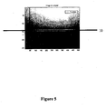
- the point of inflection I defines a scanning line 10 as represented in FIG. figure 5 .
- This scan line makes it possible to determine the visibility distance of the driver according to the characteristics of the camera.
- the calculated visibility distance may become incorrect because the horizon appears closer when the vehicle load increases. This uncertainty can be corrected by introducing the trim value of the vehicle obtained for example by means of the sensor as represented in FIG. figure 1 .
- initial or in-use calibration may be considered; this one searches for the limit of the horizon on a clear day and makes it possible to deduce the real visibility distance by compensation.
- This type of calibration can be achieved for example by a potentiometer or a software image processing.
- a detection signal can be emitted, thereby enabling the fog lamps to be turned on.
- the fog lights may be extinguished.
- Access to the visibility distance can also affect the intensity of the fog lamps depending on the impact of the fog on the visibility distance.
- the detection signal can thus serve as a control signal sent for example on a CAN (Controller Area Network) bus connected to a LCS (Light Control System) type card.
- CAN Controller Area Network
- LCS Light Control System
- This visibility distance also makes it possible to act directly on the speed of the vehicle, which can thus be regulated.
- homogeneity area search method has been described for division-fusion segmentation methods, but other segmentation methods may be used such as region division or region growth methods.
- the brightness has been described with reference to the gray level of the pixels of the image but it can also be represented by another magnitude depending on the image coding used.
- the method according to the invention has been described in the case of a fog detection but the method is also transferable to other elements disrupting the visibility of the driver such as rain, smoke or snow.
- the invention also relates to the motor vehicle using the method described above.
- the invention also relates to the possibility of modulating / adjusting the photometry of the light beam emitted by the traffic light or by the projector, in particular its light intensity.
- This modulation can be done by appropriately modulating the power supply of the light source or sources.
- This modulation is preferably controlled by means of an automated control system, taking into account one or more parameters determined by measurements obtained directly by one or more sensors or by calculation from this type of measurement.
- a particularly interesting parameter for this automated modulation is precisely the determination of the visibility distance described above.
- any other type of parameter can be chosen, such as the speed of the vehicle, or any measurement made by an infra-red camera in night vision, or any other type of camera or measuring instrument present on the vehicle, the measurement of the plate of the vehicle, or any data from a navigation system as the so-called GPS system (for Global positioning System).
- GPS system for Global positioning System
Landscapes
- Engineering & Computer Science (AREA)
- Physics & Mathematics (AREA)
- General Physics & Mathematics (AREA)
- Theoretical Computer Science (AREA)
- Geometry (AREA)
- Computer Vision & Pattern Recognition (AREA)
- Multimedia (AREA)
- Mechanical Engineering (AREA)
- Lighting Device Outwards From Vehicle And Optical Signal (AREA)
- Traffic Control Systems (AREA)
Claims (14)
- Verfahren zum Bestimmen der Sichtweite (D) des Fahrers eines Fahrzeugs bei Vorliegen eines die Sicht des Fahrers beeinträchtigenden oder verändernden Elements im Bereich des Fahrzeugumfelds, bestehend aus Nebel, Rauch, Regen oder Schnee, das einen Schritt des Erfassens wenigstens eines Bildes (6) eines Raumbereichs aufweist, wobei das Verfahren dadurch gekennzeichnet, dass es die folgenden Schritte umfasst:- einen Schritt zum Auffinden von Bereichen des Bildes, die jeweils einer Homogenitätsvorbedingung entsprechen,- Bestimmen des Schwerpunkts (G1, G2) eines jeden solchen Bereichs,- Bestimmen des Gesamtschwerpunkts (G) eines jeden dieser Schwerpunkte (G1, G2) der Bereiche,- Bestimmen einer durch den Gesamtschwerpunkt (G) verlaufenden vertikalen oder im Wesentlichen vertikalen Linie (7),- Teilen des Bildes in zwei Teile mittels der durch den Gesamtschwerpunkt (G) verlaufenden vertikalen oder im Wesentlichen vertikalen Linie (7),- Bestimmen der Helligkeit der Pixel der vertikalen oder im Wesentlichen vertikalen Linie (7) in Abhängigkeit der Höhenlage der Pixel auf der vertikalen oder im Wesentlichen vertikalen Linie (7),- Berechnen des Krümmungspunkts (I) der die Helligkeit lageabhängig darstellenden Kurve (8),- Bestimmen der Sichtweite (D) des Fahrzeugführers anhand der Lage des Krümmungspunkts (I) auf dem Bild (8).
- Verfahren nach dem vorhergehenden Anspruch,
dadurch gekennzeichnet, dass es einen Schritt des Aussendens eines Detektionssignals umfasst, wenn die Sichtweite (D) unter einen bestimmten Schwellenwert sinkt. - Verfahren nach Anspruch 1,
dadurch gekennzeichnet, dass der Schritt zum Auffinden der jeweils einer Homogenitätsvorbedingung entsprechenden Bereiche des Bildes mit einem Segmentierungsverfahren durch Unterteilen/Vereinigen ("Split and Merge") erfolgt. - Verfahren nach einem der vorhergehenden Ansprüche,
dadurch gekennzeichnet, dass die Helligkeit der Pixel durch einem Grauwert wiedergegeben ist. - Verfahren nach einem der vorhergehenden Ansprüche,
dadurch gekennzeichnet, dass das Berechnen des Krümmungspunkts der die Helligkeit lageabhängig darstellenden Kurve durch Ableitung (9) der Kurve erfolgt. - Verfahren nach einem der vorhergehenden Ansprüche,
dadurch gekennzeichnet, dass die Sichtweite unter Berücksichtigung des Fahrzeugniveaus korrigiert wird. - Verfahren nach einem der vorhergehenden Ansprüche,
dadurch gekennzeichnet, dass es zuvor einen Kalibrierungsschritt umfasst, mit dem die Horizontgrenze bei klarem Wetter bestimmt wird. - Vorrichtung (1) zum Durchführen des Verfahrens nach einem der vorhergehenden Ansprüche, mit einer Kamera (2) zum Erfassen wenigstens eines Bildes eines Raumbereichs, wobei die Vorrichtung dadurch gekennzeichnet ist, dass sie umfasst:- Mittel zum Auffinden von Bereichen des Bildes, die jeweils einer Homogenitätsvorbedingung entsprechen,- Mittel zum Bestimmen eines Schwerpunkts (G1, G2) eines jeden solchen Bereichs,- Mittel zum Bestimmen des Gesamtschwerpunkts (G) eines jeden dieser Schwerpunkte (G1, G2) der Bereiche,- Mittel zum Bestimmen einer durch den Gesamtschwerpunkt (G) verlaufenden vertikalen oder im Wesentlichen vertikalen Linie (7),- Mittel zum Teilen des Bildes in zwei Teile mittels einer durch den Gesamtschwerpunkt (G) verlaufenden vertikalen oder im Wesentlichen vertikalen Linie (7),- Mittel zum Bestimmen der Helligkeit der Pixel der vertikalen oder im Wesentlichen vertikalen Linie (7) in Abhängigkeit der Höhenlage der Pixel auf der vertikalen oder im Wesentlichen vertikalen Linie,- Mittel zum Berechnen des Krümmungspunkts der die Helligkeit lageabhängig darstellenden Kurve,- Mittel zum Bestimmen der Sichtweite des Fahrzeugführers anhand der Lage des Krümmungspunkts auf dem Bild.
- Vorrichtung nach Anspruch 8,
dadurch gekennzeichnet, dass sich die Kamera hinter der Windschutzscheibe des Fahrzeugs befindet. - Vorrichtung nach Anspruch 8,
dadurch gekennzeichnet, dass sich die Kamera im Scheinwerfer des Fahrzeugs befindet. - Vorrichtung nach einem der Ansprüche 8 bis 10,
mit einer Vorrichtung zum Senden eines Steuersignals in Abhängigkeit der Sichtweite. - Vorrichtung nach einem der Ansprüche 8 bis 11,
mit Mitteln zum Erkennen des Absinkens der Sichtweite unter einen bestimmten Schwellenwert. - System zum Steuern wenigstens eines Fahrzeug- und/oder Nebelscheinwerfers,
dadurch gekennzeichnet, dass es eine Vorrichtung nach einem der Ansprüche 11 oder 12 umfasst, deren Sendevorrichtung mit den Leistungsorganen des Fahrzeug- und/oder Nebelscheinwerfers verbunden ist, wobei das Steuersignal das Einschalten und/oder die Helligkeit des Nebel- und/oder Fahrzeugscheinwerfers in Abhängigkeit der Sichtweite regelt. - System zum Regeln der Geschwindigkeit eines Fahrzeugs,
dadurch gekennzeichnet, dass es eine Vorrichtung nach einem der Ansprüche 11 bis 12 umfasst, deren Sendevorrichtung mit einem Organ zur Steuerung der Fahrzeuggeschwindigkeit verbunden ist, wobei das Steuersignal die Fahrzeuggeschwindigkeit in Abhängigkeit der Sichtweite regelt.
Applications Claiming Priority (2)
| Application Number | Priority Date | Filing Date | Title |
|---|---|---|---|
| FR0214775 | 2002-11-19 | ||
| FR0214775A FR2847367B1 (fr) | 2002-11-19 | 2002-11-19 | Procede et dispositif de determination de la distance de visibilite du conducteur d'un vehicule |
Publications (2)
| Publication Number | Publication Date |
|---|---|
| EP1422663A1 EP1422663A1 (de) | 2004-05-26 |
| EP1422663B1 true EP1422663B1 (de) | 2014-04-16 |
Family
ID=32187814
Family Applications (1)
| Application Number | Title | Priority Date | Filing Date |
|---|---|---|---|
| EP03292599.2A Expired - Lifetime EP1422663B1 (de) | 2002-11-19 | 2003-10-17 | Verfahren und Anordnung zur Bestimmung der Sichtweite eines Fahrzeuglenkers |
Country Status (2)
| Country | Link |
|---|---|
| EP (1) | EP1422663B1 (de) |
| FR (1) | FR2847367B1 (de) |
Cited By (2)
| Publication number | Priority date | Publication date | Assignee | Title |
|---|---|---|---|---|
| US10668924B2 (en) | 2016-11-29 | 2020-06-02 | Samsung Electronics Co., Ltd. | Method and apparatus to control velocity of vehicle |
| DE102019208762A1 (de) * | 2019-06-17 | 2020-12-17 | Conti Temic Microelectronic Gmbh | Verfahren zur Steuerung von Fahrzeugscheinwerfern |
Families Citing this family (14)
| Publication number | Priority date | Publication date | Assignee | Title |
|---|---|---|---|---|
| DE102004004190A1 (de) * | 2004-01-28 | 2005-08-25 | Opel Eisenach Gmbh | Kraftfahrzeug mit einer Nebelschlussleuchte und einem Fahrassistenzsystem |
| FR2876826B1 (fr) * | 2004-10-19 | 2007-03-02 | France Etat Ponts Chaussees | Dispositif de mesure de distance de visibilite |
| FR2884637B1 (fr) * | 2005-04-19 | 2007-06-29 | Valeo Vision Sa | Procede de detection de brouillard nocturne et systeme de mise en oeuvre de ce procede |
| FR2885860B1 (fr) | 2005-05-20 | 2007-08-17 | Valeo Vision Sa | Dispositif de detection d'obstacles comportant un systeme d'imagerie pour vehicule automobile |
| FR2902556B1 (fr) | 2006-06-15 | 2008-08-15 | Valeo Vision Sa | Procede de determination d'une distance de visibilite pour un conducteur d'un vehicule. |
| JP4241834B2 (ja) | 2007-01-11 | 2009-03-18 | 株式会社デンソー | 車載霧判定装置 |
| JP4321591B2 (ja) | 2007-01-11 | 2009-08-26 | 株式会社デンソー | 車載霧判定装置 |
| FR2919727B1 (fr) | 2007-08-03 | 2010-07-30 | Valeo Vision | Procede de detection par un vehicule d'un phenomene perturbateur de visibilite |
| FR2922506B1 (fr) | 2007-10-18 | 2010-03-19 | Renault Sas | Procedes de mesure de la distance de visibilite d'un conducteur de vehicule automobile et de calcul d'une consigne de vitesse du vehicule, et systemes pour leur mise en oeuvre |
| FR2923016B1 (fr) * | 2007-10-31 | 2009-11-20 | Valeo Vision | Procede de detection d'un phenomene perturbateur de visibilite pour un vehicule. |
| FR2923933B1 (fr) * | 2007-11-16 | 2010-03-26 | Valeo Vision | Procede de detection d'un phenomene perturbateur de visibilite pour un vehicule |
| DE102008001551A1 (de) * | 2008-05-05 | 2009-11-12 | Robert Bosch Gmbh | Vorrichtung und Verfahren zum automatischen Einstellen der Leuchtdichte eines von einer Beleuchtungseinrichtung eines Fahrzeuges ausgesandten Lichtbündels in Abhängigkeit von der Sichtweite |
| US10380451B2 (en) | 2014-11-06 | 2019-08-13 | Gentex Corporation | System and method for visibility range detection |
| CN111932560B (zh) * | 2020-09-21 | 2021-01-15 | 南京安通气象数据有限公司 | 一种道路交通低能见度视频图像距离计算方法与装置 |
Family Cites Families (4)
| Publication number | Priority date | Publication date | Assignee | Title |
|---|---|---|---|---|
| FR2710014B1 (fr) * | 1993-09-15 | 1995-12-08 | Valeo Vision | Dispositif de commande automatique de l'orientation des projecteurs d'un véhicule automobile en fonction des variation d'assiette de celui-ci. |
| EP0691534B1 (de) * | 1994-07-06 | 2001-12-12 | Volkswagen Aktiengesellschaft | Verfahren zur Ermittlung der Sichtweite, insbesondere für die Bewegung eines Kraftfahrzeuges |
| US6037976A (en) * | 1995-10-31 | 2000-03-14 | Sarnoff Corporation | Method and apparatus for determining ambient conditions from an image sequence, such as fog, haze or shadows |
| DE10034461A1 (de) * | 2000-07-15 | 2002-01-31 | Bosch Gmbh Robert | Verfahren zur Sichtweitenbestimmung |
-
2002
- 2002-11-19 FR FR0214775A patent/FR2847367B1/fr not_active Expired - Fee Related
-
2003
- 2003-10-17 EP EP03292599.2A patent/EP1422663B1/de not_active Expired - Lifetime
Non-Patent Citations (1)
| Title |
|---|
| HAUTIERE N: "AMELIORATION ET EXTENSION D'UN DETECTEUR DE BROUILLARD EMBARQUE", MEMOIRE DE DEA, UNIVERSITE JEAN MONNET, SAINT-ETIENNE, FR, 12 September 2002 (2002-09-12), Laboratoire LIVIC, INRETS/LCPC, pages 1 - 113, XP008044586 * |
Cited By (2)
| Publication number | Priority date | Publication date | Assignee | Title |
|---|---|---|---|---|
| US10668924B2 (en) | 2016-11-29 | 2020-06-02 | Samsung Electronics Co., Ltd. | Method and apparatus to control velocity of vehicle |
| DE102019208762A1 (de) * | 2019-06-17 | 2020-12-17 | Conti Temic Microelectronic Gmbh | Verfahren zur Steuerung von Fahrzeugscheinwerfern |
Also Published As
| Publication number | Publication date |
|---|---|
| FR2847367A1 (fr) | 2004-05-21 |
| EP1422663A1 (de) | 2004-05-26 |
| FR2847367B1 (fr) | 2005-01-14 |
Similar Documents
| Publication | Publication Date | Title |
|---|---|---|
| EP2020595B1 (de) | Erfassungsverfahren eines Fahrzeugs für ein Störphänomen der Sicht | |
| EP1715456B1 (de) | Verfahren zur Erkennung von nächtlichem Nebel und System zur Umsetzung dieses Verfahrens | |
| EP3084511B1 (de) | System und verfahren zur steuerung der helligkeit eines headup-displays und anzeige mit verwendung des besagten systems | |
| FR2903493A1 (fr) | Dispositif de determination de conditions de visibilite pour vehicule | |
| EP2061006B1 (de) | Erfassungsverfahren eines Störphänomens der Sicht für ein Fahrzeug | |
| EP2056093B1 (de) | Verfahren zur Erkennung eines die Sichtweite eines Fahrzeuges störenden Phänomens | |
| EP1422663A1 (de) | Verfahren und Anordnung zur Bestimmung der Sichtweite eines Fahrzeuglenkers | |
| FR2710014A1 (fr) | Dispositif de commande automatique de l'orientation des projecteurs d'un véhicule automobile en fonction des variation d'assiette de celui-ci. | |
| EP3059121B1 (de) | Erzeugung und fernverarbeitung von photometriedaten | |
| WO2021122329A1 (fr) | Procédé de contrôle d'un système d'éclairage d'un véhicule automobile | |
| WO2022122853A1 (fr) | Procédé de contrôle d'un système d'éclairage intérieur d'un véhicule automobile | |
| FR3122800A1 (fr) | Procédé, dispositif et système de contrôle de feux d’éclairage d’un véhicule | |
| FR2988052A1 (fr) | Procede d'adaptation d'au moins un parametre photometrique d'une source lumineuse de vehicule automobile et systeme d'adaptation correspondant | |
| WO2024156946A1 (fr) | Procédé et dispositif de contrôle d'un système d'éclairage embarqué dans un véhicule à partir d'accélération de limites d'un objet détecté | |
| FR3040350A1 (fr) | Dispositif d'aide a la conduite pour vehicule, base sur une luminosite a venir en avant du vehicule | |
| FR3149578A1 (fr) | Procédé et dispositif d’indication de présence d’objet dans un environnement d’un véhicule | |
| EP1580074B1 (de) | Verfahren zur Detektion einer nassen Strasse und Beleuchtungssystem zu dessen Implementierung | |
| FR3107873A1 (fr) | Procédé et dispositif de contrôle d’un véhicule dans une zone météorologique à risque | |
| FR3105143A1 (fr) | Procédé de détection d’un état local de la route sur laquelle circule un véhicule automobile | |
| FR2939194A1 (fr) | Capteur de luminosite, notamment pour vehicule automobile | |
| FR3145322A1 (fr) | Procédé et dispositif de contrôle d’un système d’éclairage embarqué dans un véhicule. | |
| FR3079614A1 (fr) | Procede et dispositif de mesure des conditions de visibilite | |
| FR3104087A1 (fr) | Procédé et système de commande d’un système d’éclairage de véhicule automobile apte à commander le feu de route en fonction de conditions de roulage | |
| EP4612032A1 (de) | Verfahren und vorrichtung zur verwaltung von warnmeldungen für ein adaptives geschwindigkeitsregelsystem eines fahrzeugs | |
| WO2025068321A1 (fr) | Procédé pour le contrôle dynamique d'un système d'éclairage d'un véhicule, élément informatique, programme d'ordinateur et système d'éclairage pour la mise en œuvre du procédé |
Legal Events
| Date | Code | Title | Description |
|---|---|---|---|
| PUAI | Public reference made under article 153(3) epc to a published international application that has entered the european phase |
Free format text: ORIGINAL CODE: 0009012 |
|
| AK | Designated contracting states |
Kind code of ref document: A1 Designated state(s): AT BE BG CH CY CZ DE DK EE ES FI FR GB GR HU IE IT LI LU MC NL PT RO SE SI SK TR |
|
| AX | Request for extension of the european patent |
Extension state: AL LT LV MK |
|
| 17P | Request for examination filed |
Effective date: 20041015 |
|
| AKX | Designation fees paid |
Designated state(s): AT BE BG CH CY CZ DE DK EE ES FI FR GB GR HU IE IT LI LU MC NL PT RO SE SI SK TR |
|
| 17Q | First examination report despatched |
Effective date: 20050128 |
|
| GRAP | Despatch of communication of intention to grant a patent |
Free format text: ORIGINAL CODE: EPIDOSNIGR1 |
|
| INTG | Intention to grant announced |
Effective date: 20131107 |
|
| GRAS | Grant fee paid |
Free format text: ORIGINAL CODE: EPIDOSNIGR3 |
|
| GRAA | (expected) grant |
Free format text: ORIGINAL CODE: 0009210 |
|
| AK | Designated contracting states |
Kind code of ref document: B1 Designated state(s): AT BE BG CH CY CZ DE DK EE ES FI FR GB GR HU IE IT LI LU MC NL PT RO SE SI SK TR |
|
| REG | Reference to a national code |
Ref country code: GB Ref legal event code: FG4D Free format text: NOT ENGLISH |
|
| REG | Reference to a national code |
Ref country code: CH Ref legal event code: EP |
|
| REG | Reference to a national code |
Ref country code: AT Ref legal event code: REF Ref document number: 662947 Country of ref document: AT Kind code of ref document: T Effective date: 20140515 |
|
| REG | Reference to a national code |
Ref country code: IE Ref legal event code: FG4D Free format text: LANGUAGE OF EP DOCUMENT: FRENCH |
|
| REG | Reference to a national code |
Ref country code: DE Ref legal event code: R096 Ref document number: 60346011 Country of ref document: DE Effective date: 20140528 |
|
| REG | Reference to a national code |
Ref country code: AT Ref legal event code: MK05 Ref document number: 662947 Country of ref document: AT Kind code of ref document: T Effective date: 20140416 |
|
| REG | Reference to a national code |
Ref country code: NL Ref legal event code: VDEP Effective date: 20140416 |
|
| PG25 | Lapsed in a contracting state [announced via postgrant information from national office to epo] |
Ref country code: FI Free format text: LAPSE BECAUSE OF FAILURE TO SUBMIT A TRANSLATION OF THE DESCRIPTION OR TO PAY THE FEE WITHIN THE PRESCRIBED TIME-LIMIT Effective date: 20140416 Ref country code: NL Free format text: LAPSE BECAUSE OF FAILURE TO SUBMIT A TRANSLATION OF THE DESCRIPTION OR TO PAY THE FEE WITHIN THE PRESCRIBED TIME-LIMIT Effective date: 20140416 Ref country code: GR Free format text: LAPSE BECAUSE OF FAILURE TO SUBMIT A TRANSLATION OF THE DESCRIPTION OR TO PAY THE FEE WITHIN THE PRESCRIBED TIME-LIMIT Effective date: 20140717 Ref country code: CY Free format text: LAPSE BECAUSE OF FAILURE TO SUBMIT A TRANSLATION OF THE DESCRIPTION OR TO PAY THE FEE WITHIN THE PRESCRIBED TIME-LIMIT Effective date: 20140416 Ref country code: BG Free format text: LAPSE BECAUSE OF FAILURE TO SUBMIT A TRANSLATION OF THE DESCRIPTION OR TO PAY THE FEE WITHIN THE PRESCRIBED TIME-LIMIT Effective date: 20140716 |
|
| PG25 | Lapsed in a contracting state [announced via postgrant information from national office to epo] |
Ref country code: SE Free format text: LAPSE BECAUSE OF FAILURE TO SUBMIT A TRANSLATION OF THE DESCRIPTION OR TO PAY THE FEE WITHIN THE PRESCRIBED TIME-LIMIT Effective date: 20140416 Ref country code: ES Free format text: LAPSE BECAUSE OF FAILURE TO SUBMIT A TRANSLATION OF THE DESCRIPTION OR TO PAY THE FEE WITHIN THE PRESCRIBED TIME-LIMIT Effective date: 20140416 Ref country code: AT Free format text: LAPSE BECAUSE OF FAILURE TO SUBMIT A TRANSLATION OF THE DESCRIPTION OR TO PAY THE FEE WITHIN THE PRESCRIBED TIME-LIMIT Effective date: 20140416 |
|
| PG25 | Lapsed in a contracting state [announced via postgrant information from national office to epo] |
Ref country code: PT Free format text: LAPSE BECAUSE OF FAILURE TO SUBMIT A TRANSLATION OF THE DESCRIPTION OR TO PAY THE FEE WITHIN THE PRESCRIBED TIME-LIMIT Effective date: 20140818 |
|
| REG | Reference to a national code |
Ref country code: DE Ref legal event code: R097 Ref document number: 60346011 Country of ref document: DE |
|
| PG25 | Lapsed in a contracting state [announced via postgrant information from national office to epo] |
Ref country code: SK Free format text: LAPSE BECAUSE OF FAILURE TO SUBMIT A TRANSLATION OF THE DESCRIPTION OR TO PAY THE FEE WITHIN THE PRESCRIBED TIME-LIMIT Effective date: 20140416 Ref country code: EE Free format text: LAPSE BECAUSE OF FAILURE TO SUBMIT A TRANSLATION OF THE DESCRIPTION OR TO PAY THE FEE WITHIN THE PRESCRIBED TIME-LIMIT Effective date: 20140416 Ref country code: DK Free format text: LAPSE BECAUSE OF FAILURE TO SUBMIT A TRANSLATION OF THE DESCRIPTION OR TO PAY THE FEE WITHIN THE PRESCRIBED TIME-LIMIT Effective date: 20140416 Ref country code: CZ Free format text: LAPSE BECAUSE OF FAILURE TO SUBMIT A TRANSLATION OF THE DESCRIPTION OR TO PAY THE FEE WITHIN THE PRESCRIBED TIME-LIMIT Effective date: 20140416 Ref country code: RO Free format text: LAPSE BECAUSE OF FAILURE TO SUBMIT A TRANSLATION OF THE DESCRIPTION OR TO PAY THE FEE WITHIN THE PRESCRIBED TIME-LIMIT Effective date: 20140416 |
|
| PLBE | No opposition filed within time limit |
Free format text: ORIGINAL CODE: 0009261 |
|
| STAA | Information on the status of an ep patent application or granted ep patent |
Free format text: STATUS: NO OPPOSITION FILED WITHIN TIME LIMIT |
|
| 26N | No opposition filed |
Effective date: 20150119 |
|
| PG25 | Lapsed in a contracting state [announced via postgrant information from national office to epo] |
Ref country code: IT Free format text: LAPSE BECAUSE OF FAILURE TO SUBMIT A TRANSLATION OF THE DESCRIPTION OR TO PAY THE FEE WITHIN THE PRESCRIBED TIME-LIMIT Effective date: 20140416 |
|
| REG | Reference to a national code |
Ref country code: DE Ref legal event code: R097 Ref document number: 60346011 Country of ref document: DE Effective date: 20150119 |
|
| PG25 | Lapsed in a contracting state [announced via postgrant information from national office to epo] |
Ref country code: MC Free format text: LAPSE BECAUSE OF FAILURE TO SUBMIT A TRANSLATION OF THE DESCRIPTION OR TO PAY THE FEE WITHIN THE PRESCRIBED TIME-LIMIT Effective date: 20140416 Ref country code: LU Free format text: LAPSE BECAUSE OF FAILURE TO SUBMIT A TRANSLATION OF THE DESCRIPTION OR TO PAY THE FEE WITHIN THE PRESCRIBED TIME-LIMIT Effective date: 20141017 |
|
| REG | Reference to a national code |
Ref country code: CH Ref legal event code: PL |
|
| GBPC | Gb: european patent ceased through non-payment of renewal fee |
Effective date: 20141017 |
|
| PG25 | Lapsed in a contracting state [announced via postgrant information from national office to epo] |
Ref country code: BE Free format text: LAPSE BECAUSE OF NON-PAYMENT OF DUE FEES Effective date: 20141031 |
|
| REG | Reference to a national code |
Ref country code: IE Ref legal event code: MM4A |
|
| PG25 | Lapsed in a contracting state [announced via postgrant information from national office to epo] |
Ref country code: SI Free format text: LAPSE BECAUSE OF FAILURE TO SUBMIT A TRANSLATION OF THE DESCRIPTION OR TO PAY THE FEE WITHIN THE PRESCRIBED TIME-LIMIT Effective date: 20140416 Ref country code: GB Free format text: LAPSE BECAUSE OF NON-PAYMENT OF DUE FEES Effective date: 20141017 Ref country code: LI Free format text: LAPSE BECAUSE OF NON-PAYMENT OF DUE FEES Effective date: 20141031 Ref country code: CH Free format text: LAPSE BECAUSE OF NON-PAYMENT OF DUE FEES Effective date: 20141031 |
|
| PG25 | Lapsed in a contracting state [announced via postgrant information from national office to epo] |
Ref country code: IE Free format text: LAPSE BECAUSE OF NON-PAYMENT OF DUE FEES Effective date: 20141017 |
|
| REG | Reference to a national code |
Ref country code: FR Ref legal event code: PLFP Year of fee payment: 13 |
|
| PG25 | Lapsed in a contracting state [announced via postgrant information from national office to epo] |
Ref country code: HU Free format text: LAPSE BECAUSE OF FAILURE TO SUBMIT A TRANSLATION OF THE DESCRIPTION OR TO PAY THE FEE WITHIN THE PRESCRIBED TIME-LIMIT; INVALID AB INITIO Effective date: 20031017 Ref country code: TR Free format text: LAPSE BECAUSE OF FAILURE TO SUBMIT A TRANSLATION OF THE DESCRIPTION OR TO PAY THE FEE WITHIN THE PRESCRIBED TIME-LIMIT Effective date: 20140416 |
|
| REG | Reference to a national code |
Ref country code: FR Ref legal event code: PLFP Year of fee payment: 14 |
|
| REG | Reference to a national code |
Ref country code: FR Ref legal event code: PLFP Year of fee payment: 15 |
|
| REG | Reference to a national code |
Ref country code: FR Ref legal event code: PLFP Year of fee payment: 16 |
|
| PGFP | Annual fee paid to national office [announced via postgrant information from national office to epo] |
Ref country code: DE Payment date: 20201009 Year of fee payment: 18 Ref country code: FR Payment date: 20201030 Year of fee payment: 18 |
|
| REG | Reference to a national code |
Ref country code: DE Ref legal event code: R119 Ref document number: 60346011 Country of ref document: DE |
|
| PG25 | Lapsed in a contracting state [announced via postgrant information from national office to epo] |
Ref country code: DE Free format text: LAPSE BECAUSE OF NON-PAYMENT OF DUE FEES Effective date: 20220503 |
|
| PG25 | Lapsed in a contracting state [announced via postgrant information from national office to epo] |
Ref country code: FR Free format text: LAPSE BECAUSE OF NON-PAYMENT OF DUE FEES Effective date: 20211031 |