EP1422801A2 - Manchon de câble - Google Patents
Manchon de câble Download PDFInfo
- Publication number
- EP1422801A2 EP1422801A2 EP03026412A EP03026412A EP1422801A2 EP 1422801 A2 EP1422801 A2 EP 1422801A2 EP 03026412 A EP03026412 A EP 03026412A EP 03026412 A EP03026412 A EP 03026412A EP 1422801 A2 EP1422801 A2 EP 1422801A2
- Authority
- EP
- European Patent Office
- Prior art keywords
- sleeve
- sleeve pipe
- cable
- pipe
- pipes
- Prior art date
- Legal status (The legal status is an assumption and is not a legal conclusion. Google has not performed a legal analysis and makes no representation as to the accuracy of the status listed.)
- Withdrawn
Links
Images


Classifications
-
- H—ELECTRICITY
- H02—GENERATION; CONVERSION OR DISTRIBUTION OF ELECTRIC POWER
- H02G—INSTALLATION OF ELECTRIC CABLES OR LINES, OR OF COMBINED OPTICAL AND ELECTRIC CABLES OR LINES
- H02G15/00—Cable fittings
- H02G15/08—Cable junctions
- H02G15/10—Cable junctions protected by boxes, e.g. by distribution, connection or junction boxes
- H02G15/103—Cable junctions protected by boxes, e.g. by distribution, connection or junction boxes with devices for relieving electrical stress
-
- H—ELECTRICITY
- H02—GENERATION; CONVERSION OR DISTRIBUTION OF ELECTRIC POWER
- H02G—INSTALLATION OF ELECTRIC CABLES OR LINES, OR OF COMBINED OPTICAL AND ELECTRIC CABLES OR LINES
- H02G15/00—Cable fittings
- H02G15/08—Cable junctions
- H02G15/18—Cable junctions protected by sleeves, e.g. for communication cable
- H02G15/192—Cable junctions protected by sleeves, e.g. for communication cable with support means for ends of the sleeves
Definitions
- the invention relates to a cable sleeve according to the preamble of claim 1.
- Cable sleeves of the type mentioned here serve electrical underground Connect power supply cables.
- Such cable sleeves can be used universally for plastic-insulated cables and / or earth cables.
- connection sleeves can Cable sleeves can also be used to branch cables, for example for Branch of several plastic-insulated cables from one ground cable. In this latter Trap one speaks of transition sleeves.
- Known cable sleeves of this type especially in the medium voltage range from 10 KV to 20 KV, have a sleeve housing that consists of two screw-together. Housing half-shells is made of cast iron.
- Such known cable sleeves are heavy and therefore difficult to handle.
- the cable sleeves require Soil a relatively large hole.
- the screwing together of the half shells is especially time consuming due to their weight.
- Another essential one Disadvantage of the known cable sleeves made of cast iron half-shells is that there are spots after the usual pouring of the inside of the cable sleeve with resin can, in which between the cable and the sleeve housing little or no Cast resin is present. This leads to the operation of the cable in the area of the cable sleeve Field bundles, which in particular mechanically destroy the insulation, which over time leads to the uselessness of such an electrical line.
- the invention is based on the object, the cable reliable and trouble-free to create connecting cable sleeve that is easy to assemble.
- a cable sleeve to solve this problem has the features of claim 1.
- Such a cable sleeve which is a connecting sleeve or a transition sleeve can act, with a multi-walled socket housing ensures that the connection or branch point of the cable completely made of cast resin with a Minimum layer thickness is surrounded. This can affect the operation of the Cable, in particular field bundles, and the damage caused thereby no longer occur.
- the multi-walled socket housing is preferably composed of at least two socket pipes different diameter formed.
- Such socket pipes are easy to manufacture, in particular from plastic, which is preferably a impact-resistant thermoplastic plastic. These socket pipes are light and can also be easily installed in a small hole in the ground.
- Leave the socket pipes also a universal use of the cable sleeve according to the invention, namely both as a connecting sleeve or as a deviation sleeve. It can with such Cable sleeves Connections or branches of different cable types and Cross sections in a larger voltage range, in particular 10 KV and 20 KV, getting produced.
- the diameter is smaller (inner) sleeve pipe arranged in the larger (outer) sleeve pipe. That’s it the smaller socket pipe is completely surrounded by the larger socket pipe. It arises between the inner and the outer sleeve pipe a circumferential gap with an annular space, which leads to gaps between the outer and the inner sleeve pipe, which have a minimum size everywhere. After these gaps with resin are filled, the cable connection is completely made of casting resin with a sufficient Surround layer thickness, whereby the disadvantages of known sleeve housings mentioned can be reliably and permanently cleared out of cast iron.
- the inner sleeve pipe is shorter than the outer sleeve pipe train.
- the end faces of the inner sleeve pipe are spaced from the End faces of the larger outer sleeve pipe, so that over the open end faces of the Inner sleeve pipe Resin from the annular space between the sleeve pipes into the inner Sleeve pipe can reach and thereby this is reliably poured out, especially if according to a further preferred embodiment of the invention inner sleeve pipe with openings, for example ventilation holes, in its outer surface is provided.
- Sleeve pipes preferably both sleeve pipes, designed to be hinged.
- the Socket pipes can thereby along a continuous seam in their longitudinal direction be opened. This allows the inner sleeve pipe to be connected after the Place the cable around the mechanical connection point. Then you can do that too outer jacket tube can be placed around the inner jacket tube. So that the Sheathed pipes should always be kept at a minimum distance from each other. Spacers to be arranged between the socket pipes, which makes the circumferential and Annular gap running continuously along the length of the cable sleeve between the two Socket pipes are created.
- the socket pipe becomes the outer socket pipe evenly from the inner socket pipe spaced and this distance from the spacers permanently fixed.
- the Spacers are further designed so that they the gap between the Only partially fill in the socket pipes so that casting resin runs lengthways through the annular space can flow between the socket pipes.
- each socket pipe is made up of at least two socket pipe parts form.
- the sleeve pipe parts of both the inner sleeve pipe and the outer Socket pipe are either releasably connected to each other so that they are completely assemble separate sleeve pipe parts or there are adjacent, related sleeve pipe parts by at least one hinge, preferably one in Continuous hinge line, for example, in the longitudinal direction of the socket pipes a film hinge, foldable and connected together.
- the socket pipe parts can be easily opened for laying around the Cable connection or the inner sleeve pipe, whereby by the connection of the sleeve pipe parts the socket pipes on the hinge lines are easy to handle as a unit.
- the respective closure preferably also extends continuously in the longitudinal direction of the respective socket pipe.
- the closure can be more integral Be part of the respective socket pipe, especially the inner pipe, but also be formed by separate closure parts, in particular the outer sleeve pipe.
- the socket pipes can be moved around after being put around close the cables or the inner sleeve pipe so that they come out of the sleeve pipe parts have the jacket pipes formed with a closed jacket.
- the sleeve housing can be made from the sleeve pipes or the sleeve pipe parts Assemble quickly and easily without any screws.
- the closure of the outer jacket tube is designed in a special way.
- This closure leaves one Partially closed position, in which the jacket tube parts of the outer jacket tube are held together to form a statically closed outer casing tube, however at least one opening in the area of the closure on the top of the outer Jacket tube remains, in which cast resin can be filled. Only after the sleeve housing is completely filled with casting resin, the closure is completely closed, so that the or each pouring opening is also removed and the outer casing tube all around is closed over the entire length.
- the shield is preferably on the outer surface of the inner jacket tube applied, so that they cover the entire outer surface of the inner Extends casing tube.
- the shield can spiral around the outer surface of the inner jacket tube, so that they cover the entire inner tube Casing tube covered from the outside. Then practically trained as a bandage Shielding can be made from a metallic wire mesh or even a flexible one Wire mesh should be formed. The shield prevents external electrical interference and the emergence of electromagnetic waves from the cable sleeve, which from the to Connection of the cables exposed cable ends could emerge.
- the inside The outer casing is completely surrounded by shielding in the annulus between the two socket pipes and can be fixed using suitable fixation for example, cable connectors. After pouring the cable sleeve, if the annulus is completely filled with casting resin and this is hardened this fixes the shield reliably and permanently.
- At least some conductive, but not for energy transmission serving components of the or each cable in particular the cable shields and / or to connect reinforcements in an electrically conductive manner.
- This connection is preferably carried out via at least one grounding conductor.
- the respective ground wire is releasably connected to shields and / or armouring of the cables. Bridged the respective earth conductor the ends of the connected and / or branching cables.
- the at least one grounding conductor is in areas of the opposite end faces of the inner sleeve pipe detachable with the reinforcements or shields of the cables connected and guided along the outside of the inner jacket tube.
- the Ground wire along the inner jacket tube from the one wrapped around it Shielding and thus between the inner jacket tube and the Shield fixed.
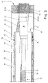
- the cable sleeve shown here is a transition sleeve 10.
- the Transition sleeve 10 is used by a ground cable 11 of the types NKBA or NAKBA to branch several, in the exemplary embodiment shown three, branch cables 12.
- Both Branch cables 12 are, for example, plastic-insulated cables of the types NAYY.
- the ground cable 11 and the branch cable 12 are laid in the ground, the Transition sleeve 10 serves the connection point 13 of the branch cable 12 with the To protect ground cable 11 and thereby to connect the ground cable 11 to the To encase branch cables 12 exposed ends thereof, to isolate them, shield and establish a ground line.
- the transition sleeve 10 has a sleeve housing 14 which, according to the invention, has multiple walls, and here is double-walled, is formed.
- the sleeve housing 14 in The embodiment shown consists of two cylindrical and single-walled socket pipes 15 and 16 formed.
- Both socket pipes 15 and 16 consist entirely of non-conductive Material, for example plastic, preferably from a thermoplastic Plastic. Different types of plastic can be used, impact-resistant thermoplastic materials are preferably used.
- the each cylindrical sleeve pipes 15 and 16 have different diameters different Lengths.
- An inner sleeve pipe 15 with a small diameter is approximately arranged concentrically in an outer sleeve pipe 16 with a larger diameter.
- the outer sleeve tube 16 has a length that is greater than the smaller inner Socket pipe 15.
- the walls of both socket pipes 15 and 16 are complete closed.
- the sleeve housing 14 of the transition sleeve 10 is completely with after assembly Cast resin filled. This cast resin filling is not shown in the figures.
- the following Description of the transition sleeve 10 refers - unless expressly stated otherwise is mentioned - on the condition of the transition sleeve not yet filled with casting resin 10. If, therefore, in the following of cavities in the socket housing 14 or open End faces of the sleeve housing 14 is mentioned, that does not refer to that Cast resin filled sleeve housing 14.
- Opposing end faces 17 of the outer sleeve pipe 16 are each one Seal 18 sealed.
- the seals 18 are designed so that when filling the Casting resin in the sleeve housing 14, the still liquid casting resin on the end faces 17th cannot exit from the outer sleeve pipe 16.
- the end faces 19 of the inner Socket pipe 15 are open.
- the length of the inner sleeve pipe 15 is formed that the end faces 15 of the same at a distance from the inner sides of the seals 18 in End area 17 of the outer sleeve pipe 16.
- the inner sleeve pipe 15 are in a known manner by cable connector 20 connected ends of the ground cable 11 of the branch cable 12.
- Die Cable connectors 20 are those at the ends of the ground cable 11 and the branch cable 12 exposed conductors 21 assigned to the same.
- the cable connector 20 can be on the ends of the conductors 21 and 22 can be fastened by screwing or crimping.
- On The end region of the earth cable 11 passes over the right side shown in FIG. 3 open end face 19 from the inner sleeve pipe 15.
- the End regions of the three branch cables 12 on the opposite left side (FIG. 2) out of the open end face 19 of the inner sleeve pipe 15.
- the End region of the earth cable 11 on the right side of the transition sleeve 10 led out of the outer sleeve pipe 16 through the seal 18.
- the three Branch cables 12 run with their end regions through the seal 18 on the left End face 17 of the outer sleeve pipe 16 (Fig. 2).
- the smaller inner sleeve pipe 15 is approximately concentric inside the larger one outer sleeve pipe 16 arranged, the diameter of the sleeve pipes 15 and 16th are dimensioned so that a circumferential gap between them with a certain one Minimum thickness is created.
- the gap runs continuously over the entire length of the inner sleeve pipe 15. In this way, between the sleeve pipes 15 and 16 Annulus 23 formed.
- Spacers 24 If the sleeve housing 14 has not yet been poured out, the approximately Concentric position of the inner sleeve pipe 15 in the outer sleeve pipe 16 fixed by Spacers 24.
- Spacers 24 In the exemplary embodiment shown there are three of the same design in one Ring-shaped spacers 24 arranged between the sleeve pipes 15 and 16.
- the spacers 24, not shown in FIGS. 1 to 3 are opposite one another End regions and a central region of the inner sleeve pipe 15 assigned.
- Both socket pipes 15 and 16 are designed so that they extend in the longitudinal direction Let assembly open.
- both the inner sleeve pipe 15 and the outer one Socket pipe 16 each consisting of two socket pipe halves 25, 26; 27 formed.
- the socket pipe halves 27 of the outer sleeve pipe 16 are of the same design.
- the sleeve tube halves 27 are connected by a hinge which in Embodiment shown as a in the longitudinal direction of the outer sleeve pipe 16th continuous, straight film hinge 28 is formed.
- the socket pipe halves 27 can be opened and closed. 4 only the closed, closed sleeve pipe 16 shown.
- the closure slide part is constructed in several parts, is made up of three about a third of the length of the outer sleeve pipe 16 extending, essentially the same length locking slide parts 32 together.
- the Locking slide parts 32 of the locking slide keep the socket tube halves 27 in place closed sleeve pipe 16 form-fitting together.
- At least one locking slide part 32 Before pouring the resin in the sleeve housing 14 is at least one locking slide part 32 in one Partially closed position brought in which the relevant slide member 32 is not is completely pushed onto the longitudinal edges 29 of the socket tube halves 27. It As a result, an opening for filling flowable remains on the top of the sleeve pipe 16 Casting resin. After the casting resin is completely in the sleeve housing 14 is filled, the relevant slide member 32 is completely on the Sleeve pipe 16 pushed and closed the respective opening. In the shown In the exemplary embodiment, three identical locking slide parts 32 are provided.
- the locking slide parts 32 of the locking slide also are made of plastic, preferably impact-resistant thermoplastic.
- the two sleeve pipe halves 25 and 26 of the inner sleeve pipe 15 are basically the same formed, namely, like the sleeve pipe halves 27 of the outer sleeve pipe 16 two roughly the same size half-cylinder shells.
- the sleeve pipe halves 25 and 26 also by a hinge, which is in The embodiment shown is also about a in the longitudinal direction of the inner sleeve pipe 15 continuous film hinge 35 is connected.
- the film hinge 35 forms one Swivel axis for pivoting the sleeve pipe halves 25 apart and together and 26. When pivoted apart, this can be opened in the longitudinal direction Socket pipe 15 around the connection and branch point between the ground cable 11 and lay the branch cable 12 around. Then the socket pipe halves 25 and 26 pivoted together, whereby the sleeve pipe 15 has an approximately cylindrical shape receives (Fig. 4).
- the sleeve pipe 15 is closed by one in the longitudinal direction thereof extending latch 36.
- the latch 36 is formed by a arranged at the upper longitudinal edge of the sleeve pipe half 25 and approximately U-shaped in cross section Locking bar 37 and a corresponding locking tongue 38 on the opposite Longitudinal edge of the adjacent socket pipe half 26.
- the two socket pipe halves 25 and 26 are compressed so far to close the socket pipe 15, that the locking tongue 38 engages at least partially in the locking bar 37 and locked by projections and depressions on the locking bar 37 and the locking tongue 38 becomes.
- the spacers 24 are placed around the inner sleeve pipe 15.
- the belt-like Spacers 24 are preferably formed from flexible plastic so that they can be easy to put around the sleeve pipe 15 in a cylindrical shape.
- the spacers 24 have at one end a cylindrical projection 47 which in a corresponding through bore 48 in the jacket of the inner sleeve pipe 15 is inserted. Through a targeted distribution of the through bores 48 the number and the position of the spacers 24 are added to the length of the socket pipe 15 specified.
- the spacer 24 has a slightly mushroom-like design Hook pin 49 on. This corresponds to a through hole 50 in opposite end portion of the spacer 24.
- the through hole: 50 is matched to the diameter of the inner sleeve pipe 15 so that the spacer 24 tightly surrounds the socket pipe 15 when the hooking pin 49 is in the through hole 50 is inserted. If necessary, several can be on the spacer 24 spaced through holes 50 may be provided, whereby the Spacer 24 is somewhat changeable in diameter, in particular can be used for transition sleeves 10 with sleeve pipes 15 of different sizes.
- the band-shaped spacer 24 has projections 51 on its outside hook 52 on, which are provided with relatively long legs 53, which are small Extend distance to the belt-shaped spacer 24 (Fig. 4). From one side can a hook 52 a flat grounding wire 43 are partially inserted so that this mostly between the band-shaped base body of the spacer 24 and the leg 53 of the hook 52 comes to rest.
- the leg preferably changes 53 to its free end 54 its distance from the band-shaped base body of the Spacer 24 by decreasing. As a result, the leg 53 clamps the Grounding wire 43 on the outside of the spacer 24 firmly.
- the spacer 24 has a plurality of hooks 52, which are alternative serve as a holder for the flat grounding wire 43.
- the spacers 24 can also be different than shown and described above be trained.
- the hooks 52 for fixing the grounding wire 43 can thus be missing.
- Spacers without projections 47 are also conceivable.
- the through holes 48 in the inner sleeve pipe 15 are eliminated.
- the connection of the ends of the belt-like spacers for closing the same can be different than the one shown Spacers 24 may be formed, for example by a variable locking connection in the way it is known in cable connectors, whereby the diameter of the closed belt of the spacer is virtually infinitely variable for adaptation to different diameters or diameter tolerances of the inner sleeve pipe 15th
- both with the lead jacket 39 and with the Reinforcement 40 by conductive, releasable fastenings, which are shown in the Embodiment is about coil springs 41, 42, one end of an earth conductor, and in the exemplary embodiment shown, a flat grounding wire 43 is attached.
- the relevant end of the grounding wire 43 is U-shaped around a first turn of the coil spring 41 laid around on the lead jacket 39, in such a way that of the roller spring 41 End region of the grounding wire 43 runs to the reinforcement 40 and here also U-shaped by one first winding of the roller spring 42 is passed around.
- the grounding wire 43 is outside on the inside Sleeve pipe 15 along to the opposite left side of the transition sleeve 10 (Fig. 1 and 2) guided and clamped in a hook 52 of each spacer 24.
- the opposite end of the ground wire 43 is on the left side of the transition sleeve 10 connected to the shields 44 of all three branch cables 12.
- Shields 44 of the branch cable 12 in the inner sleeve pipe 15 Area merged on the left side of the sleeve housing 14 and with each other twisted.
- At the twist of the shields 44 of all three branch cables 12 is one Metallic conductive cable connector 45 attached.
- On this cable connector 45 is also the end of the grounding wire 43 facing the branch cables 12 is connected in an electrically conductive manner.
- the cable connector 45 can on the twist of the shields 44 and the end of the grounding wire 43 by screws or clamps.
- a shield 46 is assigned to the outside of the inner sleeve pipe 15.
- the Shielding 46 extends over the entire outside of the socket pipe 15 is the shield 46 made of a flexible wire mesh, which is preferably lattice-like is trained.
- the shield 46 is formed from a compared to the length of the Sleeve pipe 15 narrow track of a wire mesh, which is like a bandage is wound helically around the outer jacket of the sleeve pipe 15 and thereby with overlap of the edges of the web over the entire area Outer jacket of the sleeve pipe 15 extends.
- the shield 46 is also around in Flat grounding wire 43 running along the outside of the inner sleeve tube 15 in the longitudinal direction and the spacers 24 are wrapped around so that the bandage-like shield 46 the earth wire 43 and the spacers 24 (the latter at least partially) from the outside surrounds and at the same time the grounding wire 43 on the outside of the sleeve pipe 15 fixed. Also opposite ends of the around the inner sleeve pipe 15 bandage-like shield 46 wound around is fixed on the jacket tube 15, by appropriate means, which are preferably elastic straps Plastic deals.
- Seals 18 on opposite end faces 17 of the outer casing tube 16 are so trained them to the dimensions and number of cables through the respective end face 17 can be passed, read adapt.
- the outer sleeve pipe 16 has a glued inside Sealing part 55.
- This sealing part 55 is part of the sleeve housing 16, wherein the sealing part 55 at the separation point of the sleeve pipe halves 27, that is, where that Sleeve pipe 16 is opened for assembly, is interrupted.
- Each seal 18 has also via a second sealing part 56, which around the cables, either that Ground cable 11 or the branch cable 12, is wound around, the relevant one Sealing part 56 gusset in the peripheral area of the three branch cables lying together Fill in 12.
- the sealing part 56 placed around the cables has a tab, which is in the area of the gap 31 between the upper longitudinal edges 29 of the Sleeve pipe halves 27 extends and also fills this.
- the sealing parts 56 are also self-adhesive, which means that after laying around the cables themselves get fixed.
- the sealing parts 55 and 56 of the seals 18 are formed from one elastic material that is at least partially formed from foam plastic; but other malleable and elastic material for the seals 18 are also conceivable.
- the seals 18 can also be designed as sealing sleeves. This are preferably formed from soft rubber or other rubber-like material.
- the sealing sleeves have a truncated cone-shaped cable seal for each cable, which is brought to the relevant dimension for each cable diameter.
- the Sealing grommet with the truncated cone-shaped cable seals Ground cable 11 or the branch cable 12 pushed and then a or the pipe sealing part of the sealing sleeve surrounding the cable seals from the outside via the respective end face 17 of the outer sleeve pipe 16 slipped.
- the inner sleeve tube 15 has been placed around the connection point, the grounding wire 43, the shield 44 and the spacers 24 have been installed, this is done Laying the outer jacket tube 16 around the inner jacket tube 15 and here the sealing end of the opposite end faces 17 of the outer casing tube 16 through the seals 18 to the cables. It then becomes the central top part of the closure 32 on the bends 30 on the longitudinal edges 29 of the socket tube halves 27 snapped and thereby the sleeve tube halves 27 of the outer sleeve tube 16 in one middle area held together.
- a filler for example a funnel
- flowable casting resin (after mixing the components same) poured into the double-walled sleeve housing 14.
- the sleeve housing 14 is aligned so that the socket pipes 15 and 16 run horizontally and the shutter slide parts 32 with the openings left open upwards point.
- the liquid casting resin then passes from above into the annular space 23 between the Socket pipes 15 and 16.
- the casting resin flows to opposite sides of the longer one outer sleeve pipe 16 and passes through the open end faces of the inner sleeve pipe 15 in this one. At least in the upper area of the inner sleeve pipe 15 Vent openings 57 arranged. This allows air to escape from the inner sleeve pipe 15 escape when 19 liquid casting resin in opposite Flows inside the sleeve pipe 15. It is thus guaranteed that the inside of the Sleeve housing 14, both the annular space 23 between the sleeve housings 15 and 16 as well as the entire interior of the inner sleeve pipe 15 and that of the inner Sleeve pipe 15 exposed end regions of the outer sleeve pipe 16 to the Seals 18 are filled with resin.
- the seals 18 prevent that liquid casting resin before curing even under pressure from the end faces 17 of the outer sleeve pipe 15 can not escape.
- a is approximately in the middle in the inner sleeve pipe 15 star-like spacer 58 made of plastic, in particular of the same material the casting resin, for example polyurethane, which is later to be filled into the sleeve housing 14, arranged.
- the spacer 58 is thus between the exemplary embodiment shown three branch cables 12 arranged that he the connection points to Ground cable 11 spaced apart and at a defined distance, and in such a way that this distance does not change when the sleeve housing 14 is poured out at least not significantly changes. This ensures that casting compound too between the connection points of the three branch cables 12 with the ground cable 11 is available.
- the spacer 58 made of the same material of the Casting resin is produced, it forms after the sleeve housing has been completely poured out 14 a homogeneous unit with the hardened casting resin.
- transition sleeve 10 can connecting sleeves, not shown, may also be formed.
Landscapes
- Cable Accessories (AREA)
Applications Claiming Priority (2)
| Application Number | Priority Date | Filing Date | Title |
|---|---|---|---|
| DE2002154507 DE10254507A1 (de) | 2002-11-22 | 2002-11-22 | Kabelmuffe |
| DE10254507 | 2002-11-22 |
Publications (2)
| Publication Number | Publication Date |
|---|---|
| EP1422801A2 true EP1422801A2 (fr) | 2004-05-26 |
| EP1422801A3 EP1422801A3 (fr) | 2005-07-13 |
Family
ID=32185899
Family Applications (1)
| Application Number | Title | Priority Date | Filing Date |
|---|---|---|---|
| EP03026412A Withdrawn EP1422801A3 (fr) | 2002-11-22 | 2003-11-19 | Manchon de câble |
Country Status (2)
| Country | Link |
|---|---|
| EP (1) | EP1422801A3 (fr) |
| DE (1) | DE10254507A1 (fr) |
Cited By (3)
| Publication number | Priority date | Publication date | Assignee | Title |
|---|---|---|---|---|
| CN107507705A (zh) * | 2017-10-13 | 2017-12-22 | 镇江市丹高电器有限公司 | 一种高密封性能的绝缘套管 |
| CN109407247A (zh) * | 2019-01-14 | 2019-03-01 | 徐亚琴 | 一种阻燃光缆 |
| CN111834033A (zh) * | 2020-06-29 | 2020-10-27 | 扬州金天旭电缆材料有限公司 | 一种深海电缆填充条及其制作方法 |
Family Cites Families (15)
| Publication number | Priority date | Publication date | Assignee | Title |
|---|---|---|---|---|
| US1628438A (en) * | 1927-05-10 | Cable joint | ||
| DE1870483U (de) * | 1963-02-02 | 1963-04-18 | Felten & Guilleaume Carlswerk | Kurzschlussfeste muffe fuer mehradrige elektrische starkstromkabel. |
| DE1640719A1 (de) * | 1967-08-26 | 1970-08-27 | Kabel Metallwerke Ghh | Kabelmuffe zur Verbindung zweier Einleiterkabel |
| DE1983099U (de) * | 1968-01-26 | 1968-04-11 | Kabelwerke Reinshagen G M B H | Dichte hohl-, insbesondere kabelmuffe. |
| IT959952B (it) * | 1972-06-24 | 1973-11-10 | Pirelli | Giunto perfezionato per cavi in carta impregnati in miscela e a campo radiale |
| IT970677B (it) * | 1972-06-24 | 1974-04-20 | Pirelli | Giunto perfezionato per cavi in miscela cinturati |
| US3885087A (en) * | 1973-07-17 | 1975-05-20 | Fujikura Ltd | Air tight dam for communication cables |
| NL170074C (nl) * | 1977-04-18 | 1982-09-16 | Ijzergieterij Lovink Bv | Verbinding tussen twee elektrische sterkstroomkabels. |
| DE7725964U1 (de) * | 1977-08-22 | 1977-11-24 | Kabel- Und Metallwerke Gutehoffnungshuette Ag, 3000 Hannover | Verbindungsmuffe für kunststoffisolierte einadrige elektrische Kabel |
| DE3035183A1 (de) * | 1980-09-18 | 1982-04-22 | Köttgen GmbH & Co KG, 5060 Bergisch Gladbach | Mit vergussmasse auffuellbarer muffenkoerper fuer stromkabel |
| NL8204762A (nl) * | 1982-12-08 | 1984-07-02 | Ijzergieterij Lovink Bv | Elektrisch geleidende verbinding. |
| DE3405047A1 (de) * | 1984-02-13 | 1985-08-14 | Siemens AG, 1000 Berlin und 8000 München | Stoerstrahlungssichere kabelmuffe fuer breitbandkommunikations-verstaerker |
| US4810829A (en) * | 1987-12-11 | 1989-03-07 | Minnesota Mining And Manufacturing Co. | Cable closure |
| NL1009054C2 (nl) * | 1998-05-04 | 1999-11-05 | Lovink Terborg Bv | Kabelmof. |
| DE20220434U1 (de) * | 2002-11-22 | 2003-09-04 | TECE Thews & Clüver GmbH, 28203 Bremen | Kabelmuffe |
-
2002
- 2002-11-22 DE DE2002154507 patent/DE10254507A1/de not_active Withdrawn
-
2003
- 2003-11-19 EP EP03026412A patent/EP1422801A3/fr not_active Withdrawn
Cited By (4)
| Publication number | Priority date | Publication date | Assignee | Title |
|---|---|---|---|---|
| CN107507705A (zh) * | 2017-10-13 | 2017-12-22 | 镇江市丹高电器有限公司 | 一种高密封性能的绝缘套管 |
| CN109407247A (zh) * | 2019-01-14 | 2019-03-01 | 徐亚琴 | 一种阻燃光缆 |
| CN109407247B (zh) * | 2019-01-14 | 2023-07-14 | 中动信息产业集团有限公司 | 一种阻燃光缆 |
| CN111834033A (zh) * | 2020-06-29 | 2020-10-27 | 扬州金天旭电缆材料有限公司 | 一种深海电缆填充条及其制作方法 |
Also Published As
| Publication number | Publication date |
|---|---|
| EP1422801A3 (fr) | 2005-07-13 |
| DE10254507A1 (de) | 2004-06-03 |
Similar Documents
| Publication | Publication Date | Title |
|---|---|---|
| DE3914929C2 (fr) | ||
| EP1038344B1 (fr) | Dispositif et procede permettant le maintien et le passage d'objets allonges | |
| DE2828893C2 (de) | Rohrverbinder für Kabelschutzrohre | |
| EP0268869B1 (fr) | Dispositif à tuyau protecteur en matériau synthétique pour conduites | |
| DE69609447T2 (de) | Kabelspleissumhüllung | |
| DE69834730T2 (de) | Kabelverbinder mit eingang für injektion eines fluids | |
| EP0858690B1 (fr) | Dispositif de connexion d'une enveloppe electriquement conductrice d'un cable avec un fil de masse | |
| DE2345326A1 (de) | Schutz- und isoliervorrichtung fuer eine verbindungsstelle zwischen leitungen und verfahren zur herstellung derselben | |
| DE2415641A1 (de) | Spleissbaugruppe fuer elektrische kabel | |
| DE2317242A1 (de) | Erdungsvorrichtung fuer spleissgehaeuse | |
| DE2157718A1 (de) | Telefonkabelmuffe | |
| DE10142628C2 (de) | Verschluss- und Abdichtelement | |
| EP1422801A2 (fr) | Manchon de câble | |
| DE2316053A1 (de) | Verbindungsstueck fuer koaxialkabel | |
| DE69105735T2 (de) | Hülse zum reparieren von lecken in einer rohrleitung. | |
| DE20220434U1 (de) | Kabelmuffe | |
| EP0525600A2 (fr) | Dispositif de protection de câbles destiné à une installation de conduits à poser dans le sol et à connecter à des bâtiments, coffres de tirage ou similaires | |
| DE2510195A1 (de) | Verfahren und vorrichtung zum herstellen einer loetfreien anschlussverbindung | |
| DE19816015B4 (de) | Verfahren zum Installieren eines Kabels oder Kabelstranges in ein Fahrzeugteil | |
| DE8912585U1 (de) | Manschettenartiges Abdichtelement | |
| DE3935628A1 (de) | Vorrichtung zum verlegen von buendeln flexibler leitungen an flaechen | |
| EP1717922B1 (fr) | Boîtier avec entrée de cable électrique | |
| DE69210131T2 (de) | Anordnung zum Verbinden zweier Kabel für hohe oder sehr hohe Spannung | |
| DE10355271B4 (de) | Leitungsführung für einen länglichen Körper zwischen zwei relativ zueinander bewegbaren Fahrzeugteilen | |
| DE3716252A1 (de) | Einrichtung zum abdichten von miteinander verbundenen leitern von kabeln |
Legal Events
| Date | Code | Title | Description |
|---|---|---|---|
| PUAI | Public reference made under article 153(3) epc to a published international application that has entered the european phase |
Free format text: ORIGINAL CODE: 0009012 |
|
| AK | Designated contracting states |
Kind code of ref document: A2 Designated state(s): AT BE BG CH CY CZ DE DK EE ES FI FR GB GR HU IE IT LI LU MC NL PT RO SE SI SK TR |
|
| AX | Request for extension of the european patent |
Extension state: AL LT LV MK |
|
| PUAL | Search report despatched |
Free format text: ORIGINAL CODE: 0009013 |
|
| AK | Designated contracting states |
Kind code of ref document: A3 Designated state(s): AT BE BG CH CY CZ DE DK EE ES FI FR GB GR HU IE IT LI LU MC NL PT RO SE SI SK TR |
|
| AX | Request for extension of the european patent |
Extension state: AL LT LV MK |
|
| AKX | Designation fees paid | ||
| STAA | Information on the status of an ep patent application or granted ep patent |
Free format text: STATUS: THE APPLICATION IS DEEMED TO BE WITHDRAWN |
|
| 18D | Application deemed to be withdrawn |
Effective date: 20060114 |
|
| REG | Reference to a national code |
Ref country code: DE Ref legal event code: 8566 |