EP1422939A2 - Méthode et système de projection multicannaux permettant d'obtenir de grandes surfaces de projection - Google Patents
Méthode et système de projection multicannaux permettant d'obtenir de grandes surfaces de projection Download PDFInfo
- Publication number
- EP1422939A2 EP1422939A2 EP03027088A EP03027088A EP1422939A2 EP 1422939 A2 EP1422939 A2 EP 1422939A2 EP 03027088 A EP03027088 A EP 03027088A EP 03027088 A EP03027088 A EP 03027088A EP 1422939 A2 EP1422939 A2 EP 1422939A2
- Authority
- EP
- European Patent Office
- Prior art keywords
- projection
- projectors
- image
- projector
- input signal
- Prior art date
- Legal status (The legal status is an assumption and is not a legal conclusion. Google has not performed a legal analysis and makes no representation as to the accuracy of the status listed.)
- Withdrawn
Links
Images
Classifications
-
- H—ELECTRICITY
- H04—ELECTRIC COMMUNICATION TECHNIQUE
- H04N—PICTORIAL COMMUNICATION, e.g. TELEVISION
- H04N9/00—Details of colour television systems
- H04N9/12—Picture reproducers
- H04N9/31—Projection devices for colour picture display, e.g. using electronic spatial light modulators [ESLM]
- H04N9/3141—Constructional details thereof
- H04N9/3147—Multi-projection systems
-
- H—ELECTRICITY
- H04—ELECTRIC COMMUNICATION TECHNIQUE
- H04N—PICTORIAL COMMUNICATION, e.g. TELEVISION
- H04N13/00—Stereoscopic video systems; Multi-view video systems; Details thereof
- H04N13/30—Image reproducers
- H04N13/363—Image reproducers using image projection screens
Definitions
- the invention relates to a multi-channel projection system and a method of achieving large projection surfaces.
- Video and data projectors are widely used today. This include, for example, tube projectors, D-ILA (direct image light amplification projectors, laser projectors, LCD (liquid crystal display) projectors and DLP (digital light processing) - or DMD (digital micro mirror devices) projectors.
- D-ILA direct image light amplification projectors
- laser projectors laser projectors
- LCD liquid crystal display
- DLP digital light processing
- DMD digital micro mirror devices
- the invention is therefore based on the object, a multi-channel To provide projection system, which is inexpensive can be operated.
- the projection system according to the invention is characterized in that for at least two projectors an identical, the overall picture to be projected representative input signal is present, the pixel resolution of the image to be displayed is larger than the resolution of the Projection panel of at least two projectors and means are included for electronically moving the image onto the respective panel of projectors, such that that through the individual projectors project this together projecting overall picture. This makes pixel-true Representation of the input signal achieved with which also the aspect ratio of the overall picture to be displayed is set.
- the invention is based on the idea of a projection system with several arranged side by side or one above the other Projectors, in which a single projector each projected part of the image, an identical pixel image signal to be provided for all projectors, with an electronic Move the image that defines the image to be displayed Input signal arranged on the respective projector panel is that the drawing file assigned to this projector is shown and all the sub-images together correspond to the input signal Overall picture.
- this is the invention Projection system not for scaling the input image set up, but a given projector projects one predetermined section, i.e. a predetermined pixel area within the to be represented, i.e. overall picture to be projected.
- the projection system according to the invention can Processing of analog image signals as well as for processing be set up by digital image signals.
- the projection system can in principle all projectors, especially the given above, i.e. for example projectors with LCD, DLP or D-ILA panel include.
- the at least two projectors at the same distance and with the same Projection angle to the projection plane are arranged, wherein in addition, the optics of the projectors are identical and have essentially the same setting.
- a computer system can be provided be, its graphics output with each of the one together Overall image projecting projectors is connected.
- the electronic shift of the images on the respective Projector panel can be designed such that there are partial images of individual projectors in sections on the projection surface overlay, on the other hand it is also possible that the borders of neighboring drawing files directly without a gap lie together. Add in the latter version the pixel resolutions of the side by side Projectors, which provides a particularly large projection area can be. With the cross-fade the drawing files can be a continuous transition from one Sub-image to be provided to the other when the invention Projection system is designed such that in Blend area for both sub-images whose brightness varies becomes.
- the invention can Projection system depending on the embodiment both for display an analog input signal as well as for displaying a digital one Input signal to be set up. It is the specialist understandable that the image signal to display in both cases must be available digitally on the respective projector panel.
- the means of electronic Moving the image on the panel of a projector electronic delay means for example a cable route include. Electronic moving is particularly easy of the image on the panel if a synchronization signal, for example for line synchronization as part of the image signal separated by a separate cable to Projector is fed. With a time shift of the Synchronization signal can shift the desired Image easily executed on the respective projection panel become.
- the electronic with a digital delay circuit Moving the image to the respective projector panel to be realized when the analog synchronization signal is digitized by means of a digital delay circuit delayed and then again in an analog synchronization signal is converted.
- the delay applies or shift in relation to the other information in the image signal, especially those specified one after the other Information of the individual pixels, which are in a row in a row are encoded in the image signal. Is from the computer itself a digital image signal is output, the transformation is unnecessary of the synchronization signal in the digital domain and the renewed conversion of the delayed synchronization signal back to the analog range. It goes without saying that by a corresponding adaptation of the device all types of coding of image signals can be processed.
- an exemplary projector system with two projectors will use the same image signals from an assigned computer system or by its Graphics card supplied. These images are then described as described electronically shifted onto the projector panel so that e.g. with a horizontal arrangement of the projectors the left projector of a two-channel projection system only shows the left part of the image while the right projector only the right part of the same image onto the projector surface projected such that the two drawing files together (with or without overlap) show the whole picture.
- a second such projection system operated in parallel with the first, with the two overall images overlay the projection systems with pixel accuracy in the overall picture, a stereoscopic display can be generated. Consequently are also stereoscopic representations according to the invention very large projection surfaces with the above advantages for that projection system according to the invention realizable.
- the input signals for both projection systems be different or identical. Are the two Different signals, includes a single input signal either the image for the right or the image for the left Eye of the beholder. Are the two input signals for the two projection systems identical, includes the input signal both the right eye image and the image for the left eye, both stereoscopic fields are accordingly put together in a single input signal.
- This embodiment has over the previous one has the advantage that even for stereoscopic Representation of only a single computer with an associated one Graphics card is required, since this with the one it issues Input signal, which is a pixel representation of the two stereoscopic Drawing files in an overall representation is that provides all required information. For every projector panel the projection system then becomes the corresponding one Image section selected and displayed.
- the invention solves the above object with a Process for obtaining large image projection areas under Use of a multi-channel projection system with at least two projectors arranged side by side or one above the other, with a single projector each part of the image projected.
- the process is characterized in that at least two projectors at the same distance and at the same Projection angle to the projection plane and the identical optics of the projectors are set the same, whereby for the projection of the partial images of the at least two Projectors used a substantially identical input signal becomes and the resolution of the images to be displayed larger is the possible maximum resolution of the projector panel, where the image is electronically moved on the respective panel is such that through the at least two projectors partial images projected, which together on the projection surface the pixel-true overall image corresponding to the input signal result.
- the input signal can expediently be used for at least one of the projectors in the horizontal direction (H-Shift) and / or in the vertical Direction (V-Shift) can be shifted by one projector assigned section of the pixel image within the input signal by moving it on the projector panel select.
- multi-channel passive Projection systems with a single computer for the left or right eye of the viewer.
- Using of a conventional computer can thus be high-resolution Create large format projection screens.
- the first Computer system works synchronously, a multi-dimensional view of objects or data to be displayed can be implemented inexpensively.
- a three-dimensional representation is used of known passive (polarization filters, Infitec filters) and active (shutter glasses) aids for stereoscopic Projection reached. This makes it extremely cost-effective Systems for representation in the field of virtual reality and augmented reality or in the field of simulations or create the like.
- two can be stacked vertically arranged projectors for realizing a so-called Cave representation should be provided that a pixel square Image signal on at least one of the projector panels vertically is moved so far that the image projection surface the projector system in the vertical and horizontal directions has the same number of pixels.
- the advantages of the projection system according to the invention, respectively of the method according to the invention are essentially is based on the fact that with a monoprojection a single Computer for generating the single input signal for everyone Projectors are sufficient and inexpensive projectors are used can be whose resolution add up according to the invention leaves.
- a 1: 1 ratio from (distance of the projector to the screen / width the projection area) for each projector the space requirements greatly reduced for the projection, since the projection system according to the invention this projection ratio lowered accordingly.
- Ratio of 1: 1 working projectors horizontally arranged side by side to provide an overall picture with twice the number of pixels compared to the maximum horizontal Resolution of the projector panel, there is an effective ratio Distance / image width for the projection system according to the invention of 1: 2.
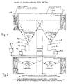
- the embodiment of the invention shown in Fig. 1 Projection system has two horizontally spaced projectors 10, 20 on. Both each include an optical system 11, 21, with which the respective projector panel, not shown in the figure is projected into the projection plane 30.
- the identical projectors are arranged so that the same distance and the same projection angle to the projection plane 30 have. Both projectors are horizontal side by side with a relative distance between the two optical Axes 12, 22 to each other. This distance is set that there is a blending area on the projection surface, that of both the left projector 10 and the right one Projector 20 is covered.
- Both projectors 10, 20 are constructed identically with a D-ILA panel which has a resolution of 1,280 x 1,024 pixels.
- the mapping of the respective projector panel onto the plane 30 results in a projection cone with an aperture angle ⁇ 0 or ⁇ 0 for both projectors, which are identical due to the equality of the projectors.
- the specified projection angles ⁇ 0 and ⁇ 0 are in each case the maximum possible image width, which is defined by the fact that all the 1,280 pixels arranged in the horizontal direction of the projector panel are used in the display.
- the projection angle ⁇ 1 is used for the projection of the image 100 on the projection surface 30 in the left projector and the projection angle ⁇ 1 is used in the right projector with the overlap region in the horizontal direction that has already been specified and is referred to in FIG. 1 as “blending”.
- the two projectors are aligned vertically to one another, so that the continuous projection image 100 results.
- a computer 50 is used to generate an input signal for the two projectors, the input signal comprising an electronic pixel representation of the overall image to be projected.
- the image signal output by the computer 50 has a resolution of 1,920 x 1,080 pixels. Accordingly, the resolution of the input signal is greater in the horizontal direction than the resolution of the projector panel.
- a means for electronically shifting the image 61, 62 on the panel of the respective projector is included in the respective signal path. Since the computer in the embodiment shown in FIG.
- the blending area comprises 256 pixels, ie 20% of the projection cone ⁇ 0 or ⁇ 0 .
- the left field does not start on left edge of the panel or the maximum possible Projection cone, but only at pixel 193 of the respective Lines.
- the delay device 61 accordingly provides on the left Projector 10 for the image signal supplied by the computer system with a horizontal resolution of 1,920 pixels on the Projector panel to the right by the specified number of pixels is moved.
- the delay device serves 62 for this purpose by a predetermined shift of the synchronization signal within the input signal provided by the computer to provide 832 pixels so that the subimage of the Projected overall image is projected, which in the line follows from line pixel 833.
- the projection system according to the invention does not include in one Embodiment shown two above one another in the vertical direction Arranged projectors, being those of the projectors generated partial images complement each other in the vertical direction.
- a projection system can be provided which one square projection surface, for example 1,280 x 1,280 Corresponds to pixels.
- Such a system is particularly useful for projections useful in the field of virtual reality.
- too three or more projectors in vertical or horizontal Direction can be arranged, the drawing files as described are generated and these add to that by the image signal Assemble the defined overall picture on the projection surface.
- both Projection systems fed with different input signals.
- the light from both projection systems is either differentiated in terms of color and / or polarization, so that with appropriate means at the viewer to create the three-dimensional effect can.
- the two different input signals are included each determined by a separate computer system. To one synchronous representation for the left and right eye of the viewer To provide, the two computer systems to each other synchronized.
- a single input signal to use for both multi-channel projection systems is provided.
- the single input signal both the pixel representation for the right eye of the Viewer assigned overall picture as well as the pixel representation the overall image assigned to the viewer's left eye includes.
- a single Computer system that outputs a single image signal is sufficient, to provide a stereoscopic projection representation.
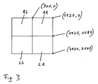
- Such an exemplary image signal is shown in FIG. 3 in a graphical representation. For the sake of simplicity, one Projection without blending.
- the input signal includes for such an exemplary stereoscopic projection system two projectors each for displaying the image for the right eye of the viewer and two projectors for displaying the image for the viewer's left eye.
- the input signal shown in Fig. 3 in the pixel representation a total resolution of 1,920 x 2,160 pixels.
- This Image is in four marked with the letters RL, RR, LL and LR Image sections divided, which the respective Image sections of a projector. Accordingly, RL and RR the two partial images for the right eye and LL and LR the two drawing files for the left eye.
- the big picture of 1,920 x 2,160 pixels is achieved by shifting the image on the panel of the respective projector so that the projector assigned image area (i.e.RL, RR, LL or LR) projected becomes. This results in a stereographic one Projection image with a resolution of 1,920 x 1,080 pixels.
- the Hardware costs can be greatly reduced if funds are provided are the input signal on each projector panel in a predetermined Move horizontally and / or vertically, in such a way that the desired overall picture results.
Landscapes
- Engineering & Computer Science (AREA)
- Multimedia (AREA)
- Signal Processing (AREA)
- Control Of Indicators Other Than Cathode Ray Tubes (AREA)
- Testing, Inspecting, Measuring Of Stereoscopic Televisions And Televisions (AREA)
- Projection Apparatus (AREA)
Applications Claiming Priority (2)
| Application Number | Priority Date | Filing Date | Title |
|---|---|---|---|
| DE10255004 | 2002-11-25 | ||
| DE10255004 | 2002-11-25 |
Publications (2)
| Publication Number | Publication Date |
|---|---|
| EP1422939A2 true EP1422939A2 (fr) | 2004-05-26 |
| EP1422939A3 EP1422939A3 (fr) | 2004-08-04 |
Family
ID=32185944
Family Applications (1)
| Application Number | Title | Priority Date | Filing Date |
|---|---|---|---|
| EP03027088A Withdrawn EP1422939A3 (fr) | 2002-11-25 | 2003-11-25 | Méthode et système de projection multicannaux permettant d'obtenir de grandes surfaces de projection |
Country Status (1)
| Country | Link |
|---|---|
| EP (1) | EP1422939A3 (fr) |
Cited By (2)
| Publication number | Priority date | Publication date | Assignee | Title |
|---|---|---|---|---|
| DE102016013994A1 (de) | 2016-11-23 | 2018-05-24 | domeprojection.com GmbH | Verfahren zur automatischen Erzeugung einer optischen Blendmaske |
| WO2026040879A1 (fr) * | 2024-08-21 | 2026-02-26 | 惠州Tcl移动通信有限公司 | Procédé et appareil de projection, support de stockage et dispositif électronique |
Family Cites Families (5)
| Publication number | Priority date | Publication date | Assignee | Title |
|---|---|---|---|---|
| US4974073A (en) * | 1988-01-14 | 1990-11-27 | Metavision Inc. | Seamless video display |
| US5193000A (en) * | 1991-08-28 | 1993-03-09 | Stereographics Corporation | Multiplexing technique for stereoscopic video system |
| JP3735158B2 (ja) * | 1996-06-06 | 2006-01-18 | オリンパス株式会社 | 画像投影システム、画像処理装置 |
| JPH10276455A (ja) * | 1997-03-28 | 1998-10-13 | Sony Corp | 映像表示方法および映像表示装置 |
| EP1107064A3 (fr) * | 1999-12-06 | 2004-12-29 | Olympus Optical Co., Ltd. | Appareil d'exposition |
-
2003
- 2003-11-25 EP EP03027088A patent/EP1422939A3/fr not_active Withdrawn
Cited By (5)
| Publication number | Priority date | Publication date | Assignee | Title |
|---|---|---|---|---|
| DE102016013994A1 (de) | 2016-11-23 | 2018-05-24 | domeprojection.com GmbH | Verfahren zur automatischen Erzeugung einer optischen Blendmaske |
| WO2018095449A1 (fr) | 2016-11-23 | 2018-05-31 | domeprojection.com GmbH | Procédé de production automatique d'un masque de fusion optique |
| DE102016013994B4 (de) | 2016-11-23 | 2019-01-17 | domeprojection.com GmbH | Verfahren zur automatischen Erzeugung einer optischen Blendmaske |
| US10944944B2 (en) | 2016-11-23 | 2021-03-09 | domeprojection.com GmbH | Automatically producing an optical blend mask individually adapted to a projector and its position to a projection surface of the projection system |
| WO2026040879A1 (fr) * | 2024-08-21 | 2026-02-26 | 惠州Tcl移动通信有限公司 | Procédé et appareil de projection, support de stockage et dispositif électronique |
Also Published As
| Publication number | Publication date |
|---|---|
| EP1422939A3 (fr) | 2004-08-04 |
Similar Documents
| Publication | Publication Date | Title |
|---|---|---|
| DE69510474T2 (de) | Verfahren und Vorrichtung zur sequentiellen Farbbildformung | |
| DE69215058T2 (de) | Dreidimensionale Bildwiedergabeeinrichtung, die elektrisch erzeugte Parallaxstreifen verwendet | |
| DE69619308T2 (de) | Vorrichtung zum Generieren stereoskopischer Bilder und Darstellung derselben | |
| DE19953595B4 (de) | Verfahren und Vorrichtung zur Verarbeitung dreidimensionaler Bilder | |
| DE69933436T2 (de) | Bildverarbeitungsvorrichtung und -verfahren | |
| EP2153269B1 (fr) | Procédé permettant d'aligner un écran barrière de parallaxe sur un écran | |
| DE69608491T2 (de) | Vorrichtung zur dreidimensionalen Bildanzeige | |
| EP2143282A1 (fr) | Procédé et dispositif de représentation tridimensionnelle | |
| DE112007000095T5 (de) | Bildfeld-Sequentielles Autostereografisches Display | |
| EP0584752B1 (fr) | Procédé pour la représentation d'images stéréoscopiques | |
| DE19545356C2 (de) | Vorrichtung zur Darstellung von Stereo-Videobildern | |
| DE19517356C1 (de) | Videosystem | |
| DE69326216T2 (de) | Flüssigkristallanzeigevorrichtung | |
| DE4143074A1 (de) | Verfahren und einrichtung zum umformatieren verschachtelter videodaten zur darstellung auf einem computer-ausgabedisplay | |
| EP0945031B1 (fr) | Procede et agencement de circuits pour transformer le format d'images electroniques tridimensionnelles formees par polarisation horizontale | |
| DE19953596B4 (de) | Vorrichtung zur Steuerung von LCD-Shutter-Brillen | |
| EP1422939A2 (fr) | Méthode et système de projection multicannaux permettant d'obtenir de grandes surfaces de projection | |
| EP1133173A2 (fr) | Procédé et dispositif de traitement d'un signal vidéo | |
| DE102012002442B3 (de) | Verfahren und Vorrichtung zur Aufbereitung von Videosignalen für stereoskopische oder Multiview-fähige Mehrsegment-Projektionsanlagen | |
| EP1680929B1 (fr) | Commande de stereoprojection | |
| EP0770306A1 (fr) | Procede et dispositif pour le traitement d'une image video | |
| DE102004020541B4 (de) | Anordnung und Verfahren zur Ansteuerung mehrerer Grafikdisplays | |
| DE60207741T2 (de) | Gerät und verfahren zur anzeige von dreidimensionalen bildern | |
| EP3907987B1 (fr) | Procédé et dispositif de projection des images individuelles pour une pluralité d'observateurs | |
| WO2011151044A2 (fr) | Procédé et dispositif de représentation tridimensionnelle |
Legal Events
| Date | Code | Title | Description |
|---|---|---|---|
| PUAI | Public reference made under article 153(3) epc to a published international application that has entered the european phase |
Free format text: ORIGINAL CODE: 0009012 |
|
| AK | Designated contracting states |
Kind code of ref document: A2 Designated state(s): AT BE BG CH CY CZ DE DK EE ES FI FR GB GR HU IE IT LI LU MC NL PT RO SE SI SK TR |
|
| AX | Request for extension of the european patent |
Extension state: AL LT LV MK |
|
| PUAL | Search report despatched |
Free format text: ORIGINAL CODE: 0009013 |
|
| AK | Designated contracting states |
Kind code of ref document: A3 Designated state(s): AT BE BG CH CY CZ DE DK EE ES FI FR GB GR HU IE IT LI LU MC NL PT RO SE SI SK TR |
|
| AX | Request for extension of the european patent |
Extension state: AL LT LV MK |
|
| RIC1 | Information provided on ipc code assigned before grant |
Ipc: 7H 04N 9/12 B Ipc: 7H 04N 13/00 B Ipc: 7H 04N 5/74 A |
|
| 17P | Request for examination filed |
Effective date: 20050204 |
|
| AKX | Designation fees paid |
Designated state(s): DE FR GB IT |
|
| STAA | Information on the status of an ep patent application or granted ep patent |
Free format text: STATUS: THE APPLICATION IS DEEMED TO BE WITHDRAWN |
|
| 18D | Application deemed to be withdrawn |
Effective date: 20070601 |