EP1423623B1 - Freilauf mit einem mit faserverstärktem kunststoff umwickelten freilaufaussenring - Google Patents
Freilauf mit einem mit faserverstärktem kunststoff umwickelten freilaufaussenring Download PDFInfo
- Publication number
- EP1423623B1 EP1423623B1 EP02769894A EP02769894A EP1423623B1 EP 1423623 B1 EP1423623 B1 EP 1423623B1 EP 02769894 A EP02769894 A EP 02769894A EP 02769894 A EP02769894 A EP 02769894A EP 1423623 B1 EP1423623 B1 EP 1423623B1
- Authority
- EP
- European Patent Office
- Prior art keywords
- free
- wheel
- reinforced plastic
- ring
- outer ring
- Prior art date
- Legal status (The legal status is an assumption and is not a legal conclusion. Google has not performed a legal analysis and makes no representation as to the accuracy of the status listed.)
- Expired - Lifetime
Links
Images


Classifications
-
- F—MECHANICAL ENGINEERING; LIGHTING; HEATING; WEAPONS; BLASTING
- F16—ENGINEERING ELEMENTS AND UNITS; GENERAL MEASURES FOR PRODUCING AND MAINTAINING EFFECTIVE FUNCTIONING OF MACHINES OR INSTALLATIONS; THERMAL INSULATION IN GENERAL
- F16D—COUPLINGS FOR TRANSMITTING ROTATION; CLUTCHES; BRAKES
- F16D41/00—Freewheels or freewheel clutches
- F16D41/06—Freewheels or freewheel clutches with intermediate wedging coupling members between an inner and an outer surface
- F16D41/069—Freewheels or freewheel clutches with intermediate wedging coupling members between an inner and an outer surface the intermediate members wedging by pivoting or rocking, e.g. sprags
- F16D41/07—Freewheels or freewheel clutches with intermediate wedging coupling members between an inner and an outer surface the intermediate members wedging by pivoting or rocking, e.g. sprags between two cylindrical surfaces
- F16D41/073—Freewheels or freewheel clutches with intermediate wedging coupling members between an inner and an outer surface the intermediate members wedging by pivoting or rocking, e.g. sprags between two cylindrical surfaces each member comprising at least two elements at different radii
Definitions
- the invention relates to a freewheel, in particular a Pinch roller or sprag freewheel with the features of Preamble of claim 1.
- a freewheel is off FR-A-0 484 583.
- Clamp freewheels are frequently used components in the art. Their use is primarily as a directional or overrunning clutch, Backstop and freewheel clutch.
- the transferable moment of a Freewheeling depends largely on the design of the shaft and the Freewheel outer ring. Often the transferable moment becomes by the widening of the gap between the shaft and the Freewheel outer ring limited. A reduction in the expansion of the Freilaufau colringes can thus increase the torque of the Freewheeling contribute.
- the invention has for its object to provide a freewheel, in which an undesirable widening of the freewheel outer ring reduced or avoided.
- the task is characterized by the features the characterizing part of claim 1 in conjunction with solved the features of the preamble.
- advantageous Embodiments of the invention are defined in the subclaims described.
- the freewheel outer ring is with wrapped in a ring of fiber reinforced plastic.
- This will be the particular hardened freewheel outer ring after the Hardening process additionally with at least one ring fiber reinforced plastic over individual ring width ranges or wrapped the entire ring width or the ring out fiber reinforced plastic will be in at least one before hardening Wrapped in the freewheel outer ring introduced circumferential groove. It can also have several circumferential grooves in the freewheel outer ring be provided. The design of the circumferential groove is like this Make that the hardened freewheel outer ring as a hub used for winding the Ringes.aus fiber-reinforced plastic can be. The laying of the fibers is done on a Winding machine with appropriate preload.
- the position of the fibers is advantageously substantially unidirectional and circumferentially about an axis so that the high modulus of elasticity of the fiber is exploited. This will a widening of the freewheel outer ring due to the contact force a clamping body optimally counteracted. The result is a higher transmissible moment, since the clamping body due to the less expansion of a gap between a shaft and the Freewheel outer ring rolls less far and thus at the same time permissible surface pressure is better utilized.
- the thickness of the freewheel outer ring and the depth of the circumferential Nut depend on the moment to be achieved and the Size of surface pressure between an outside Clamping surface of the clamp body and the freewheel outer ring.
- One Breakthrough the surface pressure on the freewheel outer ring on The wound ring of fiber reinforced plastic is too prevent.
- the height of the ring made of fiber-reinforced plastic should be the depth do not exceed the circumferential groove in the freewheel outer ring. In order to ensures that over mating surfaces, which also between can be arranged adjacent grooves, an introduction of the Freewheel outer ring in a corresponding housing without Violation of the fibers is possible.
- the width of the circumferential groove and thus the ring of fiber reinforced plastic can advantageously have the width of the clamp body or exceed.
- the wrapping of the ring of fiber reinforced Plastic is made so that the entire width of the circulating Groove is filled with fibers.
- the freewheel according to the invention has a ring fiber reinforced plastic, opposite the freewheel outer ring is formed considerably reinforced.
- the outside diameter of the Freewheel outer ring is about 1.02 - 1.1 times the Diameter of the outside clamping surface. It is the Outer diameter of the ring made of fiber-reinforced plastic, for example 1.3-1.8 times the diameter of the outside Clamping surface of the freewheel according to the invention. It arises Freewheel with one over the ring of fiber-reinforced Plastic filigree freewheel outer ring cladding.
- a Combination of such a thin running freewheel outer ring with has such a reinforced ring of fiber reinforced plastic in vibration tests as particularly resilient and proven durable.
- the invention is applicable to the radial expansion of Steel rings due to internal stress such as internal pressure, Counteract surface pressure or contact forces.
- internal stress such as internal pressure, Counteract surface pressure or contact forces.
- the freewheel consists of a shaft 1 (or a per se known freewheel inner ring - not shown) and a Partially illustrated freewheel outer ring 3, which is a common axis 2 arranged one inside the other, against each other are rotatable and thereby form a gap 4.
- this gap 4 are e.g. arranged three clamping body 5, the radially an inside Clamping surface 6 and an outside clamping surface 7 have, the are applied to the shaft 1 and the freewheel outer ring 3 and thus form a frictional connection.
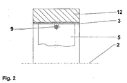
- the freewheel outer ring 3 can at Outer diameter a circumferential groove 11, preferably before hardening of the freewheel outer ring 3 is introduced possess.
- a circumferential groove 11 is a ring made of fiber Plastic 12 to prevent or reduce expansion of the freewheel outer ring 3 wrapped.
- the direction of the fibers is preferably unidirectional. This will a high elastic modulus of the wound ring of fiber reinforced Plastic 12 ensures that is higher than the Elasticity module of the freewheel outer ring 3. This ensures that the expansion of the entire freewheel outer ring 3 as a result of Contact force of the clamping body 5 is reduced. This reduces the angle of rotation between the shaft 1 and the freewheel outer ring 3 with effect of a moment, whereby the Clamping body 5 can also roll less. This has in the Generally results in a higher torque. By the lower specific gravity of the fiber reinforced plastic reduces the mass of the freewheel outer ring 3 against the a massive steel ring. Accordingly, an insert for dynamic applications, such as high switching frequencies, favors. Furthermore, a space reduction, at approximately the same Moment, by reducing the outer diameter of the freewheel outer ring 3 can be achieved. .
- the depth of the circumferential groove 11 must be chosen so that the Effect of the surface pressure by the freewheel outer ring 3 from Steel can be included and not wound on the Ring made of fiber-reinforced plastic 12 passes.
- the height of the wound ring of fiber reinforced Plastic 12 does not exceed the height of the mating surfaces 13 to damage to the fiber reinforced plastic ring 12 when introducing the freewheel outer ring 3 in the housing 14 avoid. Furthermore, a plurality of mating surfaces 13 may be provided between which are several adjacent rings fiber reinforced plastic 12 are inserted (not shown).
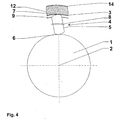
- Fig. 4 and Fig. 5 show a freewheel, the freewheel outer ring. 3 with a ring of fiber reinforced plastic 12 over the entire Width of the freewheel outer ring is wrapped. The ring off fiber reinforced plastic 12 is then in turn of a Enclosed housing 14.
- the freewheel outer ring 3 opposite the ring fiber reinforced plastic 12 significantly diluted and narrowed executed, in particular those in the claims 1 and 2 given proportions over the - of the Axis 2 measured - diameter of the outside Clamping surface 7 particularly advantageous and in endurance test detectable advantageous vibration characteristics and Generate dynamic operating characteristics of the freewheel.
- the wall thickness or wall thickness of the freewheel outer ring 3 can - ever according to size - 1 - 1.5 mm to those during operation to record occurring Hertzian pressure.
- the freewheel outer ring 3 should be in the ring of fiber reinforced Plastic 12 be pressed with a pressure fit. Under pressure by the clamping body 5 so the elastic components of thin-walled steel ring and settling processes minimized at a clearance would occur.
- the positive property of high elastic modulus (modulus of elasticity) of the fiber-reinforced ring Plastic 12 is thus effective immediately when lifting. Suitable is e.g. a mating pair H7 / n6 of fiber-reinforced ring Plastic 12 and freewheel outer ring 3.
- carbon fiber Ultra High Modulus carbon fiber Ultra High Modulus
- the ring of fiber reinforced plastic 12 can not directly in Other components are pressed, since there is a risk that the fiber is injured when pressed in and the properties of the Ringes would be negatively affected.
- the ring can be made fiber reinforced plastic 12 of FIG. 3 and FIG. 4 again from a housing 14 (or another ring, in particular an outer ring), which has the task of the ring made of fiber-reinforced plastic 12 to protect and also a Pressing into other components allows.
- the housing 14 should be made thin-walled for weight reasons and off a metallic material (e.g., steel, wrought aluminum alloys etc.) to be made.
- the Wall thickness of the housing 14 and the ring in about the Wall thickness of the freewheel outer ring 3 correspond (see Fig. 4 and Fig. 5).
- the Freewheel according to the invention as a weight-saving and low-noise Clamp body freewheel for (high performance) bicycles (especially for Bicycle hubs used), which previously for reasons of weight Used clamping roller freewheels whose noise in Purchase was taken, can be replaced.
Landscapes
- Engineering & Computer Science (AREA)
- General Engineering & Computer Science (AREA)
- Mechanical Engineering (AREA)
- Pulleys (AREA)
- Rolls And Other Rotary Bodies (AREA)
- Reinforced Plastic Materials (AREA)
- Arrangement And Driving Of Transmission Devices (AREA)
Description
- Fig. 1
- eine schematische Schnittansicht in Umfangsrichtung eines Freilaufes,
- Fig. 2
- eine erste in axialer Richtung verlaufende Schnittdarstellung des umwickelten Freilaufaußenrings nach Fig. 1,
- Fig. 3
- eine weitere in axialer Richtung verlaufende Schnittdarstellung eines umwickelten Freilaufaußenrings nach Fig. 1 mit eingebrachter Nut,
- Fig. 4
- eine schematische Schnittansicht in Umfangsrichtung eines Freilaufs mit einem Gehäuse sowie
- Fig. 5
- eine in axialer Richtung verlaufende Schnittdarstellung eines Freilaufes gemäß Fig. 4.
- 1
- Welle
- 2
- Achse
- 3
- Freilaufaußenring
- 4
- Spalt
- 5
- Klemmkörper
- 6
- innenseitige Klemmfläche
- 7
- außenseitige Klemmfläche
- 8
- Klemmkörperkäfig
- 9
- Zugfeder
- 11
- umlaufende Nut
- 12
- Ring aus faserverstärktem Kunststoff
- 13
- Paßflächen
- 14
- Gehäuse
Claims (8)
- Freilauf, insbesondere Klemmrollen- oder Klemmkörperfreilauf, mit um eine gemeinsame Achse (2) ineinander angeordneten, zueinander verdrehbaren Elementen (1,3) die einen Spalt (4) bilden, in dem Klemmelemente, insbesondere Klemmrollen oder Klemmkörper (5) so angeordnet sind, daß mit den zugewandten Mantelflächen der Elemente (1,3) über die Klemmflächen (6,7) eine reibschlüssige Verbindung herstellbar ist, wobei des äußere Element einer Freilaufaußenring (3) bildet,
dadurch gekennzeichnet, daß der Freilaufaußenring (3) mit einem Ring aus faserverstärktem Kunststoff (12) umwickelt ist und der Außendurchmesser des Rings aus faserverstärktem Kunststoff (12) etwa das 1,3 - 1,8fache des Durchmessers der außenseitigen Klemmfläche (7) beträgt. - Freilauf nach Anspruch 1,
dadurch gekennzeichnet, daß der Außendurchmesser des Freilaufaußenrings (3) etwa das 1,02 - 1,1fache des Durchmessers der außenseitigen Klemmfläche (7) beträgt. - Freilauf nach Anspruch 1 oder 2,
dadurch gekennzeichnet, daß der Elastizitätsmodul des faserverstärkten Kunststoffes (12) höher ist, als der Elastizitätsmodul des Freilaufaußenrings (3). - Freilauf nach Anspruch 3,
dadurch gekennzeichnet, daß der Elastizitätsmodul des faserverstärkten Kunststoffes (12) 210 GPa (also 210 x 103 N/mm2) übersteigt. - Freilauf nach einem der Ansprüche 1 - 4,
dadurch gekennzeichnet, daß in den Freilaufaußenring (3) eine umlaufende Nut (11) eingebracht ist, in die der Ring aus faserverstärktem Kunststoff (12) eingewickelt ist. - Freilauf nach einem der Ansprüche 1 - 5,
dadurch gekennzeichnet, daß die Höhe des Ringes aus faserverstärktem Kunststoff (12) nicht über die Paßflächen (13) des Freilaufaußenrings (3) hinausragt. - Freilauf nach einem der Ansprüche 1 - 6,
dadurch gekennzeichnet, daß die Wicklungen des Ringes aus faserverstärktem Kunststoff (12) mehrlagig ausgeführt sind. - Freilauf nach einem der Ansprüche 1 - 7,
dadurch gekennzeichnet, daß die Wicklungen des Ringes aus faserverstärktem Kunststoff (12) im wesentlichen unidirektional in Umfangsrichtung angeordnet sind.
Applications Claiming Priority (3)
| Application Number | Priority Date | Filing Date | Title |
|---|---|---|---|
| DE10144032A DE10144032A1 (de) | 2001-09-07 | 2001-09-07 | Freilauf mit einem mit faserverstärktem Kunststoff umwickelten Freilaufaußenring |
| DE10144032 | 2001-09-07 | ||
| PCT/DE2002/003161 WO2003025411A1 (de) | 2001-09-07 | 2002-08-28 | Freilauf mit einem mit faserverstärktem kunststoff umwickelten freilaufaussenring |
Publications (2)
| Publication Number | Publication Date |
|---|---|
| EP1423623A1 EP1423623A1 (de) | 2004-06-02 |
| EP1423623B1 true EP1423623B1 (de) | 2005-11-09 |
Family
ID=7698145
Family Applications (1)
| Application Number | Title | Priority Date | Filing Date |
|---|---|---|---|
| EP02769894A Expired - Lifetime EP1423623B1 (de) | 2001-09-07 | 2002-08-28 | Freilauf mit einem mit faserverstärktem kunststoff umwickelten freilaufaussenring |
Country Status (9)
| Country | Link |
|---|---|
| US (1) | US7175011B2 (de) |
| EP (1) | EP1423623B1 (de) |
| JP (1) | JP2005502849A (de) |
| CN (1) | CN1280551C (de) |
| AT (1) | ATE309484T1 (de) |
| DE (2) | DE10144032A1 (de) |
| ES (1) | ES2253559T3 (de) |
| TW (1) | TW544496B (de) |
| WO (1) | WO2003025411A1 (de) |
Families Citing this family (4)
| Publication number | Priority date | Publication date | Assignee | Title |
|---|---|---|---|---|
| FR2858376B1 (fr) * | 2003-07-28 | 2006-03-03 | Skf France | Dispositif de palier a roue libre avec limitateur de couple. |
| DE102011110199A1 (de) * | 2011-08-16 | 2013-02-21 | Dt Swiss Ag | Nabe |
| KR101993331B1 (ko) * | 2013-01-03 | 2019-06-27 | 삼성디스플레이 주식회사 | 유기발광표시장치 및 그 제조방법 |
| US11796015B1 (en) | 2022-03-31 | 2023-10-24 | GM Global Technology Operations LLC | Disengageable one-way directional sprag clutch |
Family Cites Families (12)
| Publication number | Priority date | Publication date | Assignee | Title |
|---|---|---|---|---|
| US3304138A (en) * | 1964-08-14 | 1967-02-14 | Gen Motors Corp | Antifriction bearing |
| FR1566763A (de) | 1968-03-29 | 1969-05-09 | ||
| US3974009A (en) * | 1969-05-21 | 1976-08-10 | Rex Chainbelt Inc. | Method for making ball and socket type bearings in multiple |
| US4370899A (en) * | 1978-09-13 | 1983-02-01 | U.S. Flywheels, Inc. | Flywheel for kinetic energy storage |
| US4817453A (en) * | 1985-12-06 | 1989-04-04 | E. I. Dupont De Nemours And Company | Fiber reinforced centrifuge rotor |
| DE59007465D1 (de) | 1990-11-09 | 1994-11-17 | Borg Warner Automotive Gmbh | Klemmkörper-Freilauf mit einem Käfigring. |
| US5234390A (en) | 1992-01-09 | 1993-08-10 | Borg-Warner Automotive Transmission And Engine Components Corporation | Gear transmission with undulating surface clutch and brake element connections |
| US5485905A (en) * | 1994-04-01 | 1996-01-23 | Rader, Iii; H. John | Lightweight overrunning clutch assembly |
| EP0770796B1 (de) * | 1995-10-27 | 2000-04-12 | Koyo Seiko Co., Ltd. | Freilaufkupplung |
| DE19732425C2 (de) * | 1997-07-28 | 2001-01-04 | Adler Kunststofftechnik Inh Wi | Verbundwerkstoff aus faserverstärktem Polyurethan und einem Thermoplasten sowie Verfahren zu dessen Herstellung |
| JP2000055134A (ja) * | 1998-08-06 | 2000-02-22 | Fuji Heavy Ind Ltd | 複合材フライホイール装置 |
| KR100704808B1 (ko) * | 2001-08-28 | 2007-04-10 | 도레이 가부시끼가이샤 | Cfrp제 판재 및 그의 제조 방법 |
-
2001
- 2001-09-07 DE DE10144032A patent/DE10144032A1/de not_active Withdrawn
-
2002
- 2002-08-28 US US10/489,562 patent/US7175011B2/en not_active Expired - Fee Related
- 2002-08-28 JP JP2003529010A patent/JP2005502849A/ja active Pending
- 2002-08-28 AT AT02769894T patent/ATE309484T1/de not_active IP Right Cessation
- 2002-08-28 EP EP02769894A patent/EP1423623B1/de not_active Expired - Lifetime
- 2002-08-28 DE DE50204895T patent/DE50204895D1/de not_active Expired - Fee Related
- 2002-08-28 ES ES02769894T patent/ES2253559T3/es not_active Expired - Lifetime
- 2002-08-28 WO PCT/DE2002/003161 patent/WO2003025411A1/de not_active Ceased
- 2002-08-28 CN CNB028174739A patent/CN1280551C/zh not_active Expired - Fee Related
- 2002-09-05 TW TW091120272A patent/TW544496B/zh not_active IP Right Cessation
Also Published As
| Publication number | Publication date |
|---|---|
| JP2005502849A (ja) | 2005-01-27 |
| US7175011B2 (en) | 2007-02-13 |
| US20050016812A1 (en) | 2005-01-27 |
| EP1423623A1 (de) | 2004-06-02 |
| DE50204895D1 (de) | 2005-12-15 |
| WO2003025411A8 (de) | 2004-07-08 |
| WO2003025411A1 (de) | 2003-03-27 |
| DE10144032A1 (de) | 2003-04-03 |
| ES2253559T3 (es) | 2006-06-01 |
| TW544496B (en) | 2003-08-01 |
| CN1551954A (zh) | 2004-12-01 |
| CN1280551C (zh) | 2006-10-18 |
| ATE309484T1 (de) | 2005-11-15 |
Similar Documents
| Publication | Publication Date | Title |
|---|---|---|
| DE10317116B4 (de) | Kupplungseinrichtung | |
| DE10143386B4 (de) | Parksperre für ein Kraftfahrzeug | |
| DE69827553T2 (de) | Turbomolekularpumpe | |
| EP2000699B1 (de) | Torsionsschwingungsdämpfer oder Dekoppler mit gewickelten Drahtfedern in einer Antriebsscheibe | |
| WO2007118441A2 (de) | Anordnung zum dämpfen von schwingungen an einem triebrad zum antreiben eines nebenaggregats eines fahrzeugs | |
| DE4225225C2 (de) | Drehmomentbegrenzer | |
| DE102015224608A1 (de) | Riemenscheibenentkoppler | |
| DE69113361T2 (de) | Lagerisolator. | |
| DE102012210100A1 (de) | Freilauf, insbesondere für ein Kurbel-CVT-Getriebe | |
| DE19829469B4 (de) | Riemenscheibe | |
| DE102008057222B4 (de) | Lageranordnung | |
| WO2003081064A1 (de) | Vorrichtung zur kopplung einer gehäuseanordnung einer kopplungseinrichtung mit einer rotoranordnung einer elektromaschine | |
| DE102017004974A1 (de) | Riemenscheibenentkoppler | |
| EP1423623B1 (de) | Freilauf mit einem mit faserverstärktem kunststoff umwickelten freilaufaussenring | |
| DE102018102577A1 (de) | Kupplungsvorrichtung | |
| DE102011082215A1 (de) | Freilauf, insbesondere für ein Kurbel CVT | |
| EP3984764B1 (de) | Freilaufnabe mit feder aus kunststoff mit zelliger struktur | |
| DE69800479T2 (de) | Leistungsgetriebe mit komprimiertem, elastischem Ringelement zwischen äusserem Ring und innerer Nabe | |
| DE102008016798B4 (de) | Wälzlager sowie Lenkgetriebe mit einem derartigen Wälzlager | |
| DE19531639A1 (de) | Drehschwingungsdämpfer | |
| DE102020114264A1 (de) | Schwingungsentkoppeltes Wälzlager | |
| DE10221625A1 (de) | Vorrichtung zur Kopplung einer Gehäuseanordnung einer Kopplungseinrichtung mit einer Rotoranordnung einer Elektromaschine | |
| DE69400232T2 (de) | Elastische Wellenkupplung | |
| DE69611157T2 (de) | Spiralförmige freilaufkupplung | |
| DE102012215443A1 (de) | Anordnung zum gehäuseseitigen Lagern eines Wellen- oder Nabenelementes |
Legal Events
| Date | Code | Title | Description |
|---|---|---|---|
| PUAI | Public reference made under article 153(3) epc to a published international application that has entered the european phase |
Free format text: ORIGINAL CODE: 0009012 |
|
| 17P | Request for examination filed |
Effective date: 20040319 |
|
| AK | Designated contracting states |
Kind code of ref document: A1 Designated state(s): AT BE BG CH CY CZ DE DK EE ES FI FR GB GR IE IT LI LU MC NL PT SE SK TR |
|
| GRAP | Despatch of communication of intention to grant a patent |
Free format text: ORIGINAL CODE: EPIDOSNIGR1 |
|
| GRAS | Grant fee paid |
Free format text: ORIGINAL CODE: EPIDOSNIGR3 |
|
| GRAA | (expected) grant |
Free format text: ORIGINAL CODE: 0009210 |
|
| AK | Designated contracting states |
Kind code of ref document: B1 Designated state(s): AT BE BG CH CY CZ DE DK EE ES FI FR GB GR IE IT LI LU MC NL PT SE SK TR |
|
| PG25 | Lapsed in a contracting state [announced via postgrant information from national office to epo] |
Ref country code: NL Free format text: LAPSE BECAUSE OF FAILURE TO SUBMIT A TRANSLATION OF THE DESCRIPTION OR TO PAY THE FEE WITHIN THE PRESCRIBED TIME-LIMIT Effective date: 20051109 Ref country code: CZ Free format text: LAPSE BECAUSE OF FAILURE TO SUBMIT A TRANSLATION OF THE DESCRIPTION OR TO PAY THE FEE WITHIN THE PRESCRIBED TIME-LIMIT Effective date: 20051109 Ref country code: IE Free format text: LAPSE BECAUSE OF FAILURE TO SUBMIT A TRANSLATION OF THE DESCRIPTION OR TO PAY THE FEE WITHIN THE PRESCRIBED TIME-LIMIT Effective date: 20051109 Ref country code: FI Free format text: LAPSE BECAUSE OF FAILURE TO SUBMIT A TRANSLATION OF THE DESCRIPTION OR TO PAY THE FEE WITHIN THE PRESCRIBED TIME-LIMIT Effective date: 20051109 Ref country code: SK Free format text: LAPSE BECAUSE OF FAILURE TO SUBMIT A TRANSLATION OF THE DESCRIPTION OR TO PAY THE FEE WITHIN THE PRESCRIBED TIME-LIMIT Effective date: 20051109 |
|
| REG | Reference to a national code |
Ref country code: GB Ref legal event code: FG4D Free format text: NOT ENGLISH |
|
| REG | Reference to a national code |
Ref country code: CH Ref legal event code: EP |
|
| REG | Reference to a national code |
Ref country code: IE Ref legal event code: FG4D Free format text: LANGUAGE OF EP DOCUMENT: GERMAN |
|
| REF | Corresponds to: |
Ref document number: 50204895 Country of ref document: DE Date of ref document: 20051215 Kind code of ref document: P |
|
| PG25 | Lapsed in a contracting state [announced via postgrant information from national office to epo] |
Ref country code: GR Free format text: LAPSE BECAUSE OF FAILURE TO SUBMIT A TRANSLATION OF THE DESCRIPTION OR TO PAY THE FEE WITHIN THE PRESCRIBED TIME-LIMIT Effective date: 20060209 Ref country code: DK Free format text: LAPSE BECAUSE OF FAILURE TO SUBMIT A TRANSLATION OF THE DESCRIPTION OR TO PAY THE FEE WITHIN THE PRESCRIBED TIME-LIMIT Effective date: 20060209 Ref country code: SE Free format text: LAPSE BECAUSE OF FAILURE TO SUBMIT A TRANSLATION OF THE DESCRIPTION OR TO PAY THE FEE WITHIN THE PRESCRIBED TIME-LIMIT Effective date: 20060209 Ref country code: BG Free format text: LAPSE BECAUSE OF FAILURE TO SUBMIT A TRANSLATION OF THE DESCRIPTION OR TO PAY THE FEE WITHIN THE PRESCRIBED TIME-LIMIT Effective date: 20060209 |
|
| GBT | Gb: translation of ep patent filed (gb section 77(6)(a)/1977) |
Effective date: 20060227 |
|
| PG25 | Lapsed in a contracting state [announced via postgrant information from national office to epo] |
Ref country code: PT Free format text: LAPSE BECAUSE OF FAILURE TO SUBMIT A TRANSLATION OF THE DESCRIPTION OR TO PAY THE FEE WITHIN THE PRESCRIBED TIME-LIMIT Effective date: 20060410 |
|
| NLV1 | Nl: lapsed or annulled due to failure to fulfill the requirements of art. 29p and 29m of the patents act | ||
| REG | Reference to a national code |
Ref country code: ES Ref legal event code: FG2A Ref document number: 2253559 Country of ref document: ES Kind code of ref document: T3 |
|
| REG | Reference to a national code |
Ref country code: IE Ref legal event code: FD4D |
|
| ET | Fr: translation filed | ||
| PG25 | Lapsed in a contracting state [announced via postgrant information from national office to epo] |
Ref country code: BE Free format text: LAPSE BECAUSE OF NON-PAYMENT OF DUE FEES Effective date: 20060831 Ref country code: MC Free format text: LAPSE BECAUSE OF NON-PAYMENT OF DUE FEES Effective date: 20060831 |
|
| PLBE | No opposition filed within time limit |
Free format text: ORIGINAL CODE: 0009261 |
|
| STAA | Information on the status of an ep patent application or granted ep patent |
Free format text: STATUS: NO OPPOSITION FILED WITHIN TIME LIMIT |
|
| 26N | No opposition filed |
Effective date: 20060810 |
|
| BERE | Be: lapsed |
Owner name: PAUL MULLER G.M.B.H. & CO. KG UNTERNEHMENSBETEILI Effective date: 20060831 |
|
| PG25 | Lapsed in a contracting state [announced via postgrant information from national office to epo] |
Ref country code: EE Free format text: LAPSE BECAUSE OF FAILURE TO SUBMIT A TRANSLATION OF THE DESCRIPTION OR TO PAY THE FEE WITHIN THE PRESCRIBED TIME-LIMIT Effective date: 20051109 |
|
| PG25 | Lapsed in a contracting state [announced via postgrant information from national office to epo] |
Ref country code: LU Free format text: LAPSE BECAUSE OF NON-PAYMENT OF DUE FEES Effective date: 20060828 Ref country code: TR Free format text: LAPSE BECAUSE OF FAILURE TO SUBMIT A TRANSLATION OF THE DESCRIPTION OR TO PAY THE FEE WITHIN THE PRESCRIBED TIME-LIMIT Effective date: 20051109 |
|
| PGFP | Annual fee paid to national office [announced via postgrant information from national office to epo] |
Ref country code: CH Payment date: 20080825 Year of fee payment: 7 Ref country code: ES Payment date: 20080828 Year of fee payment: 7 |
|
| PG25 | Lapsed in a contracting state [announced via postgrant information from national office to epo] |
Ref country code: CY Free format text: LAPSE BECAUSE OF FAILURE TO SUBMIT A TRANSLATION OF THE DESCRIPTION OR TO PAY THE FEE WITHIN THE PRESCRIBED TIME-LIMIT Effective date: 20051109 |
|
| PGFP | Annual fee paid to national office [announced via postgrant information from national office to epo] |
Ref country code: FR Payment date: 20080818 Year of fee payment: 7 Ref country code: IT Payment date: 20080825 Year of fee payment: 7 Ref country code: AT Payment date: 20080821 Year of fee payment: 7 |
|
| PGFP | Annual fee paid to national office [announced via postgrant information from national office to epo] |
Ref country code: GB Payment date: 20080822 Year of fee payment: 7 |
|
| PGFP | Annual fee paid to national office [announced via postgrant information from national office to epo] |
Ref country code: DE Payment date: 20081031 Year of fee payment: 7 |
|
| REG | Reference to a national code |
Ref country code: CH Ref legal event code: PL |
|
| GBPC | Gb: european patent ceased through non-payment of renewal fee |
Effective date: 20090828 |
|
| PG25 | Lapsed in a contracting state [announced via postgrant information from national office to epo] |
Ref country code: CH Free format text: LAPSE BECAUSE OF NON-PAYMENT OF DUE FEES Effective date: 20090831 Ref country code: LI Free format text: LAPSE BECAUSE OF NON-PAYMENT OF DUE FEES Effective date: 20090831 |
|
| REG | Reference to a national code |
Ref country code: FR Ref legal event code: ST Effective date: 20100430 |
|
| PG25 | Lapsed in a contracting state [announced via postgrant information from national office to epo] |
Ref country code: AT Free format text: LAPSE BECAUSE OF NON-PAYMENT OF DUE FEES Effective date: 20090828 |
|
| PG25 | Lapsed in a contracting state [announced via postgrant information from national office to epo] |
Ref country code: DE Free format text: LAPSE BECAUSE OF NON-PAYMENT OF DUE FEES Effective date: 20100302 Ref country code: FR Free format text: LAPSE BECAUSE OF NON-PAYMENT OF DUE FEES Effective date: 20090831 |
|
| REG | Reference to a national code |
Ref country code: ES Ref legal event code: FD2A Effective date: 20090829 |
|
| PG25 | Lapsed in a contracting state [announced via postgrant information from national office to epo] |
Ref country code: GB Free format text: LAPSE BECAUSE OF NON-PAYMENT OF DUE FEES Effective date: 20090828 |
|
| PG25 | Lapsed in a contracting state [announced via postgrant information from national office to epo] |
Ref country code: IT Free format text: LAPSE BECAUSE OF NON-PAYMENT OF DUE FEES Effective date: 20090828 |
|
| PG25 | Lapsed in a contracting state [announced via postgrant information from national office to epo] |
Ref country code: ES Free format text: LAPSE BECAUSE OF NON-PAYMENT OF DUE FEES Effective date: 20090829 |