EP1424009B1 - Knetmaschine für Teigmittel, insbesondere für Backwaren - Google Patents
Knetmaschine für Teigmittel, insbesondere für Backwaren Download PDFInfo
- Publication number
- EP1424009B1 EP1424009B1 EP03024239A EP03024239A EP1424009B1 EP 1424009 B1 EP1424009 B1 EP 1424009B1 EP 03024239 A EP03024239 A EP 03024239A EP 03024239 A EP03024239 A EP 03024239A EP 1424009 B1 EP1424009 B1 EP 1424009B1
- Authority
- EP
- European Patent Office
- Prior art keywords
- arms
- kneading
- rotation
- kneading machine
- machine according
- Prior art date
- Legal status (The legal status is an assumption and is not a legal conclusion. Google has not performed a legal analysis and makes no representation as to the accuracy of the status listed.)
- Expired - Lifetime
Links
- 238000004898 kneading Methods 0.000 title claims description 73
- 235000015173 baked goods and baking mixes Nutrition 0.000 title description 3
- 235000013305 food Nutrition 0.000 title description 2
- 230000001360 synchronised effect Effects 0.000 claims description 2
- 238000010008 shearing Methods 0.000 description 7
- 230000009471 action Effects 0.000 description 6
- 230000008901 benefit Effects 0.000 description 5
- 230000005540 biological transmission Effects 0.000 description 5
- 230000000694 effects Effects 0.000 description 4
- 230000006872 improvement Effects 0.000 description 2
- 238000004519 manufacturing process Methods 0.000 description 2
- 230000008859 change Effects 0.000 description 1
- 239000003638 chemical reducing agent Substances 0.000 description 1
- 238000010276 construction Methods 0.000 description 1
- 230000002708 enhancing effect Effects 0.000 description 1
- 235000013312 flour Nutrition 0.000 description 1
- 239000004615 ingredient Substances 0.000 description 1
- 230000002093 peripheral effect Effects 0.000 description 1
- 230000009467 reduction Effects 0.000 description 1
- 238000009877 rendering Methods 0.000 description 1
Images


Classifications
-
- B—PERFORMING OPERATIONS; TRANSPORTING
- B01—PHYSICAL OR CHEMICAL PROCESSES OR APPARATUS IN GENERAL
- B01F—MIXING, e.g. DISSOLVING, EMULSIFYING OR DISPERSING
- B01F27/00—Mixers with rotary stirring devices in fixed receptacles; Kneaders
- B01F27/05—Stirrers
- B01F27/11—Stirrers characterised by the configuration of the stirrers
- B01F27/112—Stirrers characterised by the configuration of the stirrers with arms, paddles, vanes or blades
- B01F27/1126—Stirrers characterised by the configuration of the stirrers with arms, paddles, vanes or blades the stirrer being a bent rod supported at one end only
-
- A—HUMAN NECESSITIES
- A21—BAKING; EDIBLE DOUGHS
- A21C—MACHINES OR EQUIPMENT FOR MAKING OR PROCESSING DOUGHS; HANDLING BAKED ARTICLES MADE FROM DOUGH
- A21C1/00—Mixing or kneading machines for the preparation of dough
- A21C1/02—Mixing or kneading machines for the preparation of dough with vertically-mounted tools; Machines for whipping or beating
-
- A—HUMAN NECESSITIES
- A21—BAKING; EDIBLE DOUGHS
- A21C—MACHINES OR EQUIPMENT FOR MAKING OR PROCESSING DOUGHS; HANDLING BAKED ARTICLES MADE FROM DOUGH
- A21C1/00—Mixing or kneading machines for the preparation of dough
- A21C1/14—Structural elements of mixing or kneading machines; Parts; Accessories
- A21C1/1405—Tools
-
- B—PERFORMING OPERATIONS; TRANSPORTING
- B01—PHYSICAL OR CHEMICAL PROCESSES OR APPARATUS IN GENERAL
- B01F—MIXING, e.g. DISSOLVING, EMULSIFYING OR DISPERSING
- B01F27/00—Mixers with rotary stirring devices in fixed receptacles; Kneaders
- B01F27/80—Mixers with rotary stirring devices in fixed receptacles; Kneaders with stirrers rotating about a substantially vertical axis
- B01F27/805—Mixers with rotary stirring devices in fixed receptacles; Kneaders with stirrers rotating about a substantially vertical axis wherein the stirrers or the receptacles are moved in order to bring them into operative position; Means for fixing the receptacle
- B01F27/806—Mixers with rotary stirring devices in fixed receptacles; Kneaders with stirrers rotating about a substantially vertical axis wherein the stirrers or the receptacles are moved in order to bring them into operative position; Means for fixing the receptacle with vertical displacement of the stirrer, e.g. in combination with means for pivoting the stirrer about a vertical axis in order to co-operate with different receptacles
-
- B—PERFORMING OPERATIONS; TRANSPORTING
- B01—PHYSICAL OR CHEMICAL PROCESSES OR APPARATUS IN GENERAL
- B01F—MIXING, e.g. DISSOLVING, EMULSIFYING OR DISPERSING
- B01F27/00—Mixers with rotary stirring devices in fixed receptacles; Kneaders
- B01F27/80—Mixers with rotary stirring devices in fixed receptacles; Kneaders with stirrers rotating about a substantially vertical axis
- B01F27/805—Mixers with rotary stirring devices in fixed receptacles; Kneaders with stirrers rotating about a substantially vertical axis wherein the stirrers or the receptacles are moved in order to bring them into operative position; Means for fixing the receptacle
- B01F27/807—Mixers with rotary stirring devices in fixed receptacles; Kneaders with stirrers rotating about a substantially vertical axis wherein the stirrers or the receptacles are moved in order to bring them into operative position; Means for fixing the receptacle with the stirrer-head pivoting about a horizontal axis to bring it in and out of operative position, e.g. with receptacles pivoting about a horizontal axis for emptying
-
- B—PERFORMING OPERATIONS; TRANSPORTING
- B01—PHYSICAL OR CHEMICAL PROCESSES OR APPARATUS IN GENERAL
- B01F—MIXING, e.g. DISSOLVING, EMULSIFYING OR DISPERSING
- B01F27/00—Mixers with rotary stirring devices in fixed receptacles; Kneaders
- B01F27/80—Mixers with rotary stirring devices in fixed receptacles; Kneaders with stirrers rotating about a substantially vertical axis
- B01F27/85—Mixers with rotary stirring devices in fixed receptacles; Kneaders with stirrers rotating about a substantially vertical axis with two or more stirrers on separate shafts
-
- B—PERFORMING OPERATIONS; TRANSPORTING
- B01—PHYSICAL OR CHEMICAL PROCESSES OR APPARATUS IN GENERAL
- B01F—MIXING, e.g. DISSOLVING, EMULSIFYING OR DISPERSING
- B01F27/00—Mixers with rotary stirring devices in fixed receptacles; Kneaders
- B01F27/80—Mixers with rotary stirring devices in fixed receptacles; Kneaders with stirrers rotating about a substantially vertical axis
- B01F27/90—Mixers with rotary stirring devices in fixed receptacles; Kneaders with stirrers rotating about a substantially vertical axis with paddles or arms
- B01F27/902—Mixers with rotary stirring devices in fixed receptacles; Kneaders with stirrers rotating about a substantially vertical axis with paddles or arms cooperating with intermeshing elements fixed on the receptacle walls
- B01F27/9021—Mixers with rotary stirring devices in fixed receptacles; Kneaders with stirrers rotating about a substantially vertical axis with paddles or arms cooperating with intermeshing elements fixed on the receptacle walls the elements being vertically arranged, e.g. fixed on the bottom
-
- B—PERFORMING OPERATIONS; TRANSPORTING
- B01—PHYSICAL OR CHEMICAL PROCESSES OR APPARATUS IN GENERAL
- B01F—MIXING, e.g. DISSOLVING, EMULSIFYING OR DISPERSING
- B01F29/00—Mixers with rotating receptacles
- B01F29/80—Mixers with rotating receptacles rotating about a substantially vertical axis
- B01F29/83—Mixers with rotating receptacles rotating about a substantially vertical axis with rotary paddles or arms, e.g. movable out of the receptacle
-
- B—PERFORMING OPERATIONS; TRANSPORTING
- B01—PHYSICAL OR CHEMICAL PROCESSES OR APPARATUS IN GENERAL
- B01F—MIXING, e.g. DISSOLVING, EMULSIFYING OR DISPERSING
- B01F35/00—Accessories for mixers; Auxiliary operations or auxiliary devices; Parts or details of general application
- B01F35/75—Discharge mechanisms
-
- B—PERFORMING OPERATIONS; TRANSPORTING
- B01—PHYSICAL OR CHEMICAL PROCESSES OR APPARATUS IN GENERAL
- B01F—MIXING, e.g. DISSOLVING, EMULSIFYING OR DISPERSING
- B01F35/00—Accessories for mixers; Auxiliary operations or auxiliary devices; Parts or details of general application
- B01F35/75—Discharge mechanisms
- B01F35/754—Discharge mechanisms characterised by the means for discharging the components from the mixer
- B01F35/7548—Discharge mechanisms characterised by the means for discharging the components from the mixer using tilting or pivoting means for emptying the mixing receptacle
-
- B—PERFORMING OPERATIONS; TRANSPORTING
- B01—PHYSICAL OR CHEMICAL PROCESSES OR APPARATUS IN GENERAL
- B01F—MIXING, e.g. DISSOLVING, EMULSIFYING OR DISPERSING
- B01F35/00—Accessories for mixers; Auxiliary operations or auxiliary devices; Parts or details of general application
- B01F35/90—Heating or cooling systems
- B01F35/92—Heating or cooling systems for heating the outside of the receptacle, e.g. heated jackets or burners
-
- B—PERFORMING OPERATIONS; TRANSPORTING
- B01—PHYSICAL OR CHEMICAL PROCESSES OR APPARATUS IN GENERAL
- B01F—MIXING, e.g. DISSOLVING, EMULSIFYING OR DISPERSING
- B01F35/00—Accessories for mixers; Auxiliary operations or auxiliary devices; Parts or details of general application
- B01F35/90—Heating or cooling systems
- B01F2035/98—Cooling
-
- B—PERFORMING OPERATIONS; TRANSPORTING
- B01—PHYSICAL OR CHEMICAL PROCESSES OR APPARATUS IN GENERAL
- B01F—MIXING, e.g. DISSOLVING, EMULSIFYING OR DISPERSING
- B01F2215/00—Auxiliary or complementary information in relation with mixing
- B01F2215/04—Technical information in relation with mixing
- B01F2215/0413—Numerical information
- B01F2215/0418—Geometrical information
- B01F2215/0422—Numerical values of angles
-
- B—PERFORMING OPERATIONS; TRANSPORTING
- B01—PHYSICAL OR CHEMICAL PROCESSES OR APPARATUS IN GENERAL
- B01F—MIXING, e.g. DISSOLVING, EMULSIFYING OR DISPERSING
- B01F27/00—Mixers with rotary stirring devices in fixed receptacles; Kneaders
- B01F27/05—Stirrers
- B01F27/07—Stirrers characterised by their mounting on the shaft
- B01F27/072—Stirrers characterised by their mounting on the shaft characterised by the disposition of the stirrers with respect to the rotating axis
- B01F27/0721—Stirrers characterised by their mounting on the shaft characterised by the disposition of the stirrers with respect to the rotating axis parallel with respect to the rotating axis
-
- B—PERFORMING OPERATIONS; TRANSPORTING
- B01—PHYSICAL OR CHEMICAL PROCESSES OR APPARATUS IN GENERAL
- B01F—MIXING, e.g. DISSOLVING, EMULSIFYING OR DISPERSING
- B01F27/00—Mixers with rotary stirring devices in fixed receptacles; Kneaders
- B01F27/05—Stirrers
- B01F27/09—Stirrers characterised by the mounting of the stirrers with respect to the receptacle
- B01F27/091—Stirrers characterised by the mounting of the stirrers with respect to the receptacle with elements co-operating with receptacle wall or bottom, e.g. for scraping the receptacle wall
-
- B—PERFORMING OPERATIONS; TRANSPORTING
- B01—PHYSICAL OR CHEMICAL PROCESSES OR APPARATUS IN GENERAL
- B01F—MIXING, e.g. DISSOLVING, EMULSIFYING OR DISPERSING
- B01F27/00—Mixers with rotary stirring devices in fixed receptacles; Kneaders
- B01F27/05—Stirrers
- B01F27/11—Stirrers characterised by the configuration of the stirrers
- B01F27/112—Stirrers characterised by the configuration of the stirrers with arms, paddles, vanes or blades
- B01F27/1123—Stirrers characterised by the configuration of the stirrers with arms, paddles, vanes or blades sickle-shaped, i.e. curved in at least one direction
-
- B—PERFORMING OPERATIONS; TRANSPORTING
- B01—PHYSICAL OR CHEMICAL PROCESSES OR APPARATUS IN GENERAL
- B01F—MIXING, e.g. DISSOLVING, EMULSIFYING OR DISPERSING
- B01F27/00—Mixers with rotary stirring devices in fixed receptacles; Kneaders
- B01F27/05—Stirrers
- B01F27/11—Stirrers characterised by the configuration of the stirrers
- B01F27/112—Stirrers characterised by the configuration of the stirrers with arms, paddles, vanes or blades
- B01F27/1125—Stirrers characterised by the configuration of the stirrers with arms, paddles, vanes or blades with vanes or blades extending parallel or oblique to the stirrer axis
-
- B—PERFORMING OPERATIONS; TRANSPORTING
- B01—PHYSICAL OR CHEMICAL PROCESSES OR APPARATUS IN GENERAL
- B01F—MIXING, e.g. DISSOLVING, EMULSIFYING OR DISPERSING
- B01F27/00—Mixers with rotary stirring devices in fixed receptacles; Kneaders
- B01F27/23—Mixers with rotary stirring devices in fixed receptacles; Kneaders characterised by the orientation or disposition of the rotor axis
- B01F27/232—Mixers with rotary stirring devices in fixed receptacles; Kneaders characterised by the orientation or disposition of the rotor axis with two or more rotation axes
- B01F27/2321—Mixers with rotary stirring devices in fixed receptacles; Kneaders characterised by the orientation or disposition of the rotor axis with two or more rotation axes having different inclinations, e.g. non parallel
-
- B—PERFORMING OPERATIONS; TRANSPORTING
- B01—PHYSICAL OR CHEMICAL PROCESSES OR APPARATUS IN GENERAL
- B01F—MIXING, e.g. DISSOLVING, EMULSIFYING OR DISPERSING
- B01F27/00—Mixers with rotary stirring devices in fixed receptacles; Kneaders
- B01F27/23—Mixers with rotary stirring devices in fixed receptacles; Kneaders characterised by the orientation or disposition of the rotor axis
- B01F27/232—Mixers with rotary stirring devices in fixed receptacles; Kneaders characterised by the orientation or disposition of the rotor axis with two or more rotation axes
- B01F27/2322—Mixers with rotary stirring devices in fixed receptacles; Kneaders characterised by the orientation or disposition of the rotor axis with two or more rotation axes with parallel axes
-
- B—PERFORMING OPERATIONS; TRANSPORTING
- B01—PHYSICAL OR CHEMICAL PROCESSES OR APPARATUS IN GENERAL
- B01F—MIXING, e.g. DISSOLVING, EMULSIFYING OR DISPERSING
- B01F27/00—Mixers with rotary stirring devices in fixed receptacles; Kneaders
- B01F27/40—Mixers with rotor-rotor system, e.g. with intermeshing teeth
- B01F27/42—Mixers with rotor-rotor system, e.g. with intermeshing teeth with rotating surfaces next to each other, i.e. on substantially parallel axes
Definitions
- the present invention relates to kneading machines for food doughs, particularly for bakery products, of the type comprising a substantially cylindrical tank and a pair of kneading implements turning within the tank, with concordant directions of rotation, about two axes that are substantially parallel to the axis of the tank and are set at a distance from the axis of the tank, so as to describe two theoretical cylinders that are substantially tangential both with respect to one another, and with respect to the circumferential wall of the tank.
- a kneading machine of the type indicated above is described and illustrated in the European patent EP 354 190 B1 and in the corresponding U.S. patent US 4 919 539 in the name of the present applicant.
- the two kneading implements are in the form of helical spirals that wind about a theoretical cylindrical surface through an angle considerably greater than 180° and in a typical case even greater than 360°, which corresponds to a situation in which the axial dimension of the kneading implement is close to the value of the pitch of the helical spiral.
- a machine according to the preamble of claim 1 is known from EP-A-0 499 661.
- the subject of the present invention is a kneading machine having the features of claim 1.
- the aforesaid arms are inclined in a concordant way with respect to the generatrices of their theoretical cylinders so that when they intersect in the aforesaid area of tangency they are arranged so that they cross one another so as .to give rise to a scissors-like shearing action.
- the two arms of the kneading implements will be inclined in an opposite way with respect to the generatrices of their theoretical cylinders.
- each arm is set according to a portion of helix extending on the periphery of its theoretical cylinder, and from one end to the other of said cylinder according to an angle smaller than 180°, viewed in the direction of the axis of rotation.
- the two aforesaid theoretical cylinders have diameters and heights that are substantially equal, the two portions of helix defining on said arms are substantially equal, and the speed of rotation of the arms are also substantially equal, so that the area of tangency of the two arms shifts progressively during their intersection in a direction parallel to the axes of the two theoretical cylinders and from one end to the other of said cylinders.
- no other members are provided inside the tank other than the two kneading implements.
- the theoretical cylinders of the two kneading implements each have a diameter that is sufficiently high so that each of said cylinders, viewed in the direction of its axis, is not contained in just one quadrant of the tank.
- the plane of tangency of the two theoretical cylinders is also a diametral plane of the tank.
- each helical arm is comprised between 20° and 100° and is preferably equal to approximately 45°, whilst the angle of inclination of each helical arm is preferably comprised between 15° and 40° and in particular is substantially equal to 20°.
- each of said arms defines an edge which is substantially shearing along the cylindrical surface of the respective theoretical cylinder.
- Said cross section may, for example, be in the form of a square, or rhomboid, with the two cutting edges of the two arms set opposite to one another.
- the reference number 1 indicates as a whole a kneading machine for alimentary mixes, particularly flour-based mixes for bakery products.
- the machine 1 comprises, in a way in itself known (see, for example, the previous European patent in the name of the present applicant EP 0 354 190 B1), a fixed structure 2, to which there may be coupled a carriage 3, provided with wheels 4 and a handle 5, with the aid of a hydraulic-blocking system (also of a known type and not illustrated).
- the carriage 3 supports in a rotary way, i.e., turning about a vertical axis 6, a cylindrical tank 7 having a circular shape.
- the fixed structure 2 constitutes a casing containing a motor-reducer assembly 8, which is designed to set the tank 7 in rotation about its axis 6 by means of at least one wheel 9 that draws the tank 7 by friction, the said wheel 9 being in contact with the outer surface of a base portion 10 of the tank 7.
- the machine comprises a head structure 11, which is articulated to the fixed structure 1 by a hinge 12.
- the head structure 10 projects in cantilever fashion above the tank 4, which is designed to receive the mix and supports two kneading implements 13 in such a way that the latter turn about two axes 14 that are parallel with respect to one another and parallel moreover to the axis 6 of the rotating tank.
- the two kneading implements 13 can be driven in rotation by an electric motor 14' with a belt transmission 15, which includes a pulley 16 mounted on the shaft of the electric motor 14', a pulley 17 mounted in a rotating way in the structure of the head 11 and connected in rotation to the pulley 16 by a belt 18 (see Figure 2) and a gearcase 19 (see Figure 3), which connects in rotation the two shafts or spindles 20 that carry the kneading implements 13 (see Figure 3).
- a hydraulic cylinder 21 is provided ( Figure 1), which is controlled by a hydraulic power unit 22 driven by an electric motor 23, for raising the head structure 11 from the operating position illustrated by a solid line in Figure 1, where the two kneading implements 13 carried by the head 11 are set inside the tank 7, to a position rotated upwards about the hinge 12 (indicated by a dashed line in Figure 1, as well as illustrated in a complete way in Figure 4), where the kneading implements 13 are set completely above the tank 7 so as to enable approach of the carriage 3, with the tank 7 set above it to the structure of the machine, prior to a kneading operation, as well as recession therefrom of the carriage 3 with the tank 7 carried by it at the end of a kneading operation.
- the invention is applicable also to machines with tanks not carried by a carriage, but instead integrated in the machine.
- the machine according to the invention differs from the prior art above all on account of the conformation and disposition of the two kneading implements.
- the two implements 13 comprise two arms 13a that extend downwards, each starting from a peripheral area of two circular plates 13b carried by the two spindles 20.
- the two arms 13 extend substantially for the entire height of the tank 7 in such a way that their free ends, in the operating condition of the machine illustrated in Figure 1, are close to the bottom wall of the tank.
- Each arm 13a extends on the periphery, and from one end to the other, of a theoretical cylinder XIII having an axis coincident with the respective axis 14 of rotation of the kneading implement. As a result, each of the two arms 13a describes an orbital movement about the respective axis of rotation 14. As may be seen clearly in Figure 5, each arm 13a is inclined, at least for a part of its length (in the example illustrated for its entire length) with respect to a straight line generatrix of its theoretical cylinder XIII, parallel to the axis of rotation 14. Theoretically, the arm 13a could be set according to a rectilinear direction inclined with respect to the generatrix.
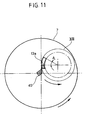
- each arm 13a has a helical configuration, corresponding to a helix of a pitch considerably greater than the height of the theoretical cylinder XIII, in such a way that the two opposite ends of each arm 13a are staggered with respect to one another, viewed in the direction of the axis of rotation (see Figure 6) by an angle A, which, in the example illustrated, is approximately 30°.
- angle A which, in the example illustrated, is approximately 30°.
- said angle is indicated here purely by way of example since it is in general sufficient for the purposes of achieving the advantages of the invention for said angle to be lower than 180°. It is in any case preferable for said angle to be between 20° and 100° and even more preferably for it to be between 20° and 45°.
- the angle of inclination of the helix defined by each arm 13a is preferably comprised between 5° and 40° and is preferably in the region of 20°.
- the conformation described above of the helix defined by each arm 13a is important in so far as it represents an essential difference with respect to conventional kneading machines with spiral kneading implements.
- the implements have a helical conformation with a pitch that is considerably smaller than the axial dimension of the respective theoretical cylinder, so that the two opposite ends of each implement are staggered with respect to one another, viewed in the direction of the axis of rotation, by an angle considerably greater than 180°.
- each arm 13a of each kneading implement passes in the area of reciprocal tangency of the two theoretical cylinders XIII only once in each revolution of the implement, which is found experimentally to constitute an important condition for the purposes of obtaining a mix of the desired quality.
- each of the two cylinders XIII are substantially tangential to one another on a diametral plane B of the tank 7 and are moreover each internally tangential to the cylindrical wall of the tank 7.
- each of the two cylinders has, according to a preferred embodiment, a diameter that is sufficiently large to cause the circular section of each cylinder to extend beyond the limits of the respective quadrant Q of the tank 7, where by "quadrant" is meant each of the four areas of the tank 7 that are delimited by the intersection of the diametral plane B with respect to the diametral plane C that is orthogonal to it.
- the cylinder XIII contained in the quadrant Q1 also projects into the quadrant Q4, and the theoretical cylinder XIII contained in the quadrant Q2 also projects into the quadrant Q3.
- the space inside the tank 7 is occupied only by the two kneading implements, without there being envisaged further members, such as for example a contrast member of the kneading implements, as is instead envisaged, for example, in the prior patent in the name of the present applicant that has been cited above.
- the two kneading implements 13 are made to rotate in a concordant way (in the example illustrated, both in the counterclockwise direction viewed from above) and also in concordance with the direction of rotation of the tank 7 (which in the example illustrated is also counterclockwise, once again as viewed from above).
- an important characteristic of the invention lies in the fact that the orbital movements of the two arms 13a about the axes 14 are synchronized with respect to one another in such a way that the two arms 13a pass simultaneously within the area of tangency of the respective theoretical cylinders XIII, intersecting one another in opposite directions of movement on account of the concordant rotation of the two implements.
- the said intersection in opposite directions of movement determines the fact that the portion of mix that is at the area of tangency is subjected to a sort of cutting action in the area of tangency between the two arms.
- the two arms are inclined in a concordant way with respect to the generatrices of their theoretical cylinders, in such a way that at their intersection in the aforesaid area of tangency they are arranged so that they cross one another, according to a scissors-like configuration, so as to enhance the aforesaid shearing effect that has been described above.
- the two arms are inclined in a discordant way (with reference to their direction of "screwing" on the respective theoretical cylinder) so that in the area of tangency they have inclinations that are parallel to one another.
- each arm may present a broken configuration, with portions of different inclination.
- each of the two arms should be set at least approximately according to a helix with the ends staggered with respect to one another by an angle smaller than 180°
- each implement has its end staggered with respect to the other by an angle greater than 180° and in general close to 360°.
- the contact in the area of tangency does not occur just once at each revolution of the implement and, furthermore, the action of thrust in an axial direction, to which the mix is subjected by the implements with helical spiral and which leads the mix being pressed against the bottom of the tank, is enhanced.
- the machine according to the invention presents also the advantage of only requiring the use of kneading implements having an extremely simple structure and low cost of fabrication.
- the duration of the kneading cycle is altogether comparable to that of traditional machines, and in particular of the machine illustrated in the prior patent that has been cited above.
- the two arms 13a present cutting edges set opposite to one another in the area of tangency.
- the two implements can have a substantially square cross section, as may be seen in Figure 6 and at an enlarged scale in Figure 7, or even a trapezial or rhomboidal cross section, as illustrated in Figures 8 and 9.
- Figure 10 illustrates a further elevation of the two kneading implements.
- the cross section of each arm thins out in the direction of its free end.
- the machine is provided with a single kneading implement of the type described above, which co-operates with a fixed contrast member, which projects downwards from the head of the machine within the rotating tank.
- Said contrast member could be represented by a fixed arm set at the area of tangency between the theoretical cylinder of the single kneading implement and the diametral plane B of the tank ( Figure 6). In this case, the shearing effect would be obtained as a result of the action of a single arm rotating in cooperation with a fixed contrast member.
Landscapes
- Chemical & Material Sciences (AREA)
- Chemical Kinetics & Catalysis (AREA)
- Life Sciences & Earth Sciences (AREA)
- Engineering & Computer Science (AREA)
- Food Science & Technology (AREA)
- Mixers Of The Rotary Stirring Type (AREA)
- Manufacturing And Processing Devices For Dough (AREA)
Claims (14)
- Knetmaschine, aufweisend:- ein Gefäß (7), das im Wesentlichen zylindrisch ist; und- ein Paar von Knetarbeitsgeräten (13), die sich in dem Gefäß (7) drehen, mit übereinstimmenden Drehrichtungen, um zwei Achsen (14) parallel zur Achse (6) des Gefäßes, welche im Wesentlichen tangential sowohl zueinander als auch zur Umgebungswand des Gefäßes (7) sind,wobei:- jedes Gefäß (13) wenigstens einen Arm (13a) aufweist;- sich jeder Arm (13a) auf der Peripherie und von einem Ende zum anderen eines theoretischen Zylinders (XIII) erstreckt, der eine Achse aufweist, die mit der jeweiligen Drehachse (14) des Arms (13a) übereinstimmt, auf solche Weise, dass der Arm (13a) eine Drehbewegung um die jeweilige Drehachse (14) herum beschreibt;- jeder Arm (13a) wenigstens an einem Teil seiner Länge geneigt ist in Bezug auf eine Mantellinie des theoretischen Zylinders (XIII) parallel zur Drehachse (14) des Armes (13a);- die gegenüberliegenden Enden der zwei Arme (13a) in Bezug aufeinander gestaffelt sind, betrachtet in Richtung der Drehachse, um einen Winkel (A) kleiner als 180° um die Drehachse (14);- Mittel bereitgestellt werden, die bewirken, dass die Arme (13a) drehende Bewegungen aufweisen, um die jeweilige Drehachse (14) herum, die in Bezug aufeinander synchronisiert sind, auf solche Weise, dass die Arme (13a) simultan einen tangentialen Bereich des jeweiligen theoretischen Zylinders (XIII) passieren, wobei sie sich gegenseitig in entgegengesetzten Bewegungsrichtungen schneiden aufgrund der übereinstimmenden Drehewegung der zwei Arbeitsgeräte,dadurch gekennzeichnet, dass:- das Gefäß (7) ein drehendes Gefäß ist,- die Drehachsen (14) der Knetarbeitswerkzeuge (13) feste Achsen sind, und- jedes Knetarbeitsgerät (13) einen einzigen Arm (13a) aufweist, wobei jeder Arm (13a) ein freies Ende hat.
- Knetmaschine nach Anspruch 1, dadurch gekennzeichnet, dass die Arme (13a) in übereinstimmender Weise in Bezug auf die Mantellinien ihrer theoretischen Zylinder (XIII) geneigt sind, auf solche Weise, dass sie bei ihrer Überschneidung im voranstehenden tangentialen Bereich so angeordnet sind, dass sie einander gemäß einer scherenartigen Konfiguration schneiden.
- Knetmaschine nach Anspruch 2, dadurch gekennzeichnet, dass jeder Arm gemäß einem Teil einer Helix angelegt ist, der sich auf der Peripherie seines theoretischen Zylinders (XIII) und von einem Ende zum anderen Ende des Zylinders gemäß einem Winkel kleiner als 180° betrachtet in der Richtung der Drehachse erstreckt.
- Knetmaschine nach Anspruch 3, dadurch gekennzeichnet, dass die zwei voranstehenden theoretischen Zylinder (XIII) Durchmesser haben, die im Wesentlichen gleich sind, und Höhen, die im Wesentlichen gleich sind, wobei die zwei Teile von Helices, die auf den Armen vorgegeben sind, im Wesentlichen gleich sind und die Drehgeschwindigkeiten der Arme ebenso im Wesentlichen gleich sind, so dass der tangentiale Bereich der zwei Arme fortwährend während ihres Überschneidens in eine Richtung parallel zu den Achsen der zwei theoretischen Zylinder (XIII) sich verschiebt und von einem Ende zum anderen der Zylinder.
- Knetmaschine nach Anspruch 1, dadurch gekennzeichnet, dass jeder der voranstehenden theoretischen Zylinder (XIII) einen Durchmesser hat, der ausreichend groß ist, so dass der Zylinder Gesamtabmessungen hat, die die Grenzen des jeweiligen Quadranten des Gefäßes (Q1, Q2) überschreiten.
- Knetmaschine nach Anspruch 5, dadurch gekennzeichnet, dass die zwei Knetarbeitsgeräte (13) die einzigen Bauteile bilden, die innerhalb des Gefäßes vorliegen.
- Knetmaschine nach Anspruch 1, dadurch gekennzeichnet, dass sich der voranstehende Winkel (A) der Staffelung der zwei gegenüberliegenden Enden von jedem Arm (13a) zwischen 20° und 100° befindet und sich bevorzugt zwischen 20° und 45° befindet.
- Knetmaschine nach Anspruch 3, dadurch gekennzeichnet, dass der voranstehende Teil der Helix einen Neigungswinkel von zwischen 15° und 40° hat.
- Knetmaschine nach Anspruch 8, dadurch gekennzeichnet, dass der voranstehende Neigungswinkel des Teils der Helix gleich ungefähr 20° ist.
- Knetmaschine nach Anspruch 1, dadurch gekennzeichnet, dass die zwei Arme (13a) jeweilige Schneidkanten (30) aufweisen, welche gegenüberliegend zueinander angelegt sind, wenn die zwei Arme (13a) einander schneiden.
- Knetmaschine nach Anspruch 10, dadurch gekennzeichnet, dass die Arme (13a) einen Querschnitt von quadratischer Gestalt haben.
- Knetmaschine nach Anspruch 10, dadurch gekennzeichnet, dass die Arme (13a) einen Querschnitt von trapezförmiger Gestalt haben.
- Knetmaschine nach Anspruch 10, dadurch gekennzeichnet, dass die Arme (13a) einen Querschnitt von rhomboedrischer Gestalt haben.
- Knetmaschine nach Anspruch 1, dadurch gekennzeichnet, dass eines der zwei Knetarbeitsgeräte (13) durch ein festes zusammenarbeitendes Bauteil ersetzt werden kann, das im Wesentlichen tangential zum theoretischen Zylinder des anderen Knetarbeitsgeräts ist.
Applications Claiming Priority (2)
| Application Number | Priority Date | Filing Date | Title |
|---|---|---|---|
| ITTO20021020 | 2002-11-26 | ||
| IT001020A ITTO20021020A1 (it) | 2002-11-26 | 2002-11-26 | Macchina impastatrice per paste alimentari particolarmente |
Publications (3)
| Publication Number | Publication Date |
|---|---|
| EP1424009A2 EP1424009A2 (de) | 2004-06-02 |
| EP1424009A3 EP1424009A3 (de) | 2004-08-25 |
| EP1424009B1 true EP1424009B1 (de) | 2006-04-19 |
Family
ID=32259983
Family Applications (1)
| Application Number | Title | Priority Date | Filing Date |
|---|---|---|---|
| EP03024239A Expired - Lifetime EP1424009B1 (de) | 2002-11-26 | 2003-10-22 | Knetmaschine für Teigmittel, insbesondere für Backwaren |
Country Status (5)
| Country | Link |
|---|---|
| US (1) | US6997597B2 (de) |
| EP (1) | EP1424009B1 (de) |
| DE (1) | DE60304657T2 (de) |
| ES (1) | ES2260559T3 (de) |
| IT (1) | ITTO20021020A1 (de) |
Families Citing this family (25)
| Publication number | Priority date | Publication date | Assignee | Title |
|---|---|---|---|---|
| ITTO20021020A1 (it) * | 2002-11-26 | 2004-05-27 | Sancassiano Spa | Macchina impastatrice per paste alimentari particolarmente |
| DE60307493T2 (de) * | 2002-03-05 | 2007-09-13 | Sancassiano S.P.A., Roddi D'alba | Knetmaschine für Teigmittel, insbesondere für Backwaren |
| ITTO20030863A1 (it) * | 2003-11-03 | 2005-05-04 | Sancassiano Spa | Macchina impastatrice orizzontale per paste alimentari, particolarmente per prodotti da forno. |
| CN101347752A (zh) * | 2008-07-28 | 2009-01-21 | 王洪福 | 搅拌剥皮机和搅拌着水机 |
| DE202008012827U1 (de) * | 2008-09-26 | 2008-11-27 | Dr. Herfeld Gmbh & Co. Kg | Mischmaschine |
| CN102327755A (zh) * | 2010-07-12 | 2012-01-25 | 南通全技纺织涂层有限公司 | 用于织物涂层浆料的搅拌机 |
| CA2754198C (en) * | 2010-09-22 | 2019-05-21 | Norman G. Schimdt | Variable diameter, variable pitch auger with material scraper and breaker bar |
| DE102011004433A1 (de) | 2011-02-21 | 2012-08-23 | Neuenkirchener Maschinenfabrik Emil Kemper Gmbh | Vorrichtung zum Bearbeiten von Teig |
| US9295264B2 (en) * | 2012-01-06 | 2016-03-29 | Anderson Group, Ltd. | Dough preparing machine with dough dividing in bowl |
| GB2508883B (en) * | 2012-12-14 | 2017-05-31 | Kenwood Ltd | Food mixing arrangement |
| DE102018106184A1 (de) | 2018-03-16 | 2019-09-19 | Maschinenfabrik Gustav Eirich Gmbh & Co. Kg | Mischvorrichtung mit Dichtung |
| CN108905733A (zh) * | 2018-07-04 | 2018-11-30 | 白健平 | 一种无纺布生产用具有减震散热功能的原料混合装置 |
| CN108905734A (zh) * | 2018-07-04 | 2018-11-30 | 白健平 | 一种无纺布生产用原料混合装置 |
| CN108991058A (zh) * | 2018-09-06 | 2018-12-14 | 佛山市蔷薇新能源科技有限公司 | 一种全自动和面装置 |
| EP3772281B1 (de) * | 2019-08-07 | 2022-04-06 | DIOSNA Dierks & Söhne GmbH | Knetmaschine für teige mit einklemmschutz und verfahren zum einschwenken eines knetwerkzeugs |
| CN111530343B (zh) * | 2020-04-30 | 2022-07-12 | 浙江慧琳工贸有限公司 | 一种油漆粉体混合装置 |
| CN111888976B (zh) * | 2020-08-03 | 2022-05-31 | 宁波百仕高联合工业有限公司 | 一种胶水制备混合搅拌加工系统及加工工艺 |
| PL3970498T3 (pl) * | 2020-09-21 | 2024-06-17 | DIOSNA Dierks & Söhne GmbH | Ugniatarka do ciast spożywczych z uszczelnieniem narzędzi ugniatających |
| CN112385675A (zh) * | 2020-11-09 | 2021-02-23 | 黄勇 | 一种加工面团用的节能环保型高效率和面机 |
| CN112791615A (zh) * | 2021-01-26 | 2021-05-14 | 吉林金祚石油科技服务有限公司 | 石油压裂用压裂液混合装置 |
| CN112934064A (zh) * | 2021-02-02 | 2021-06-11 | 湖南海鲤医疗科技有限公司 | 一种化学试剂生产用搅拌装置 |
| CN113856545B (zh) * | 2021-10-25 | 2023-09-12 | 江苏振华新云电子有限公司 | 一种钽电容器专用碱液混合配置装置及配置方法 |
| CN114345177B (zh) * | 2022-01-05 | 2023-03-21 | 故城北新建材有限公司 | 一种可旋转式混合机上搅拌装置 |
| JP7841321B2 (ja) * | 2022-03-29 | 2026-04-07 | 三浦工業株式会社 | 処理装置 |
| CN115738859A (zh) * | 2022-10-29 | 2023-03-07 | 江苏三沃电子科技有限公司 | 一种无铅助焊剂的调质方法 |
Family Cites Families (35)
| Publication number | Priority date | Publication date | Assignee | Title |
|---|---|---|---|---|
| FR820147A (fr) * | 1936-07-09 | 1937-11-04 | Organe de pétrissage pour pétrins mécaniques | |
| US2115742A (en) * | 1936-09-10 | 1938-05-03 | Roger H Newton | Mixing |
| US2184225A (en) * | 1938-06-02 | 1939-12-19 | Claude A Mcduffee | Mixing device |
| US2610042A (en) * | 1946-10-11 | 1952-09-09 | Dryon Paul | Apparatus for working pastes |
| US3262680A (en) * | 1963-09-24 | 1966-07-26 | Baker Perkins Inc | Mixer for mixing potentially explosive materials |
| DE1264407B (de) * | 1966-02-19 | 1968-03-28 | Eirich Gustav | Mischgeraet mit umlaufender Mischschuessel und in entgegengesetzter Drehrichtung angetriebenem Mischwerkzeugsystem |
| DE1959799A1 (de) * | 1969-11-28 | 1971-06-03 | Kemper Kate | Anlage zur Aufbereitung von Teigen oder aehnlichem Gut |
| US4375336A (en) * | 1979-10-03 | 1983-03-01 | Halley Louis E A | Machine for dispensing a doughy substance |
| DE3020167A1 (de) * | 1980-05-28 | 1981-12-03 | Dierks & Söhne, 4500 Osnabrück | Knet- und/oder mengmaschine |
| IT1129850B (it) * | 1980-11-13 | 1986-06-11 | San Cassiano Di Drocco A & C S | Macchina impastatrice |
| FR2546719A1 (fr) * | 1983-06-03 | 1984-12-07 | Fonderie Soc Gen De | Petrin a bras petrisseur d'axe vertical |
| ES292402Y (es) * | 1986-02-20 | 1987-02-16 | Suay Puig Enrique | Amasadora para la fabricacion de pan con extraccion automatica de la masa |
| IT1211456B (it) * | 1987-11-03 | 1989-10-26 | Sancassiano Spa | Macchina impastatrice per prodotti alimentari |
| IT215075Z2 (it) | 1988-07-05 | 1990-07-30 | Sancassiano Spa | Macchina impastatrice particolarmente per prodotti alimentari |
| FR2659528B1 (fr) * | 1990-03-14 | 1992-07-24 | Dito Sama | Dispositif d'extraction de pate notamment d'un petrin a cuve cylindrique. |
| IT1240521B (it) * | 1990-07-30 | 1993-12-17 | Sancassiano Spa | Macchina impastatrice per prodotti alimentari e procedimento di impastatura realizzabile mediante tale macchina |
| EP0496182B1 (de) * | 1991-01-17 | 1995-07-26 | Italiana Macchine Srl | Nahrungskneter mit herausziehbarem Behälter |
| EP0499661B1 (de) * | 1991-02-19 | 1995-08-23 | Inoue Seisakusho (Mfg) Co., Ltd. | Planetenmischer |
| USD344208S (en) * | 1991-07-12 | 1994-02-15 | Dito-Sama | Spiral kneader |
| IT1256511B (it) * | 1992-01-13 | 1995-12-07 | Sancassiano Spa | Macchina impastatrice per prodotti alimentari. |
| IT1256804B (it) * | 1992-02-03 | 1995-12-15 | Sancassiano Spa | Macchina impastatrice per prodotti alimentari |
| AT399442B (de) * | 1992-03-16 | 1995-05-26 | Koenig Helmut | Vorrichtung zum rühren und bzw. oder kneten von teig |
| DE4334121A1 (de) * | 1993-10-07 | 1995-04-13 | Dierks & Soehne | Maschine zum Kneten von Teig |
| IT1267144B1 (it) * | 1994-11-15 | 1997-01-28 | Sancassiano Spa | Macchina impastatrice per prodotti alimentari |
| DE19621286C2 (de) * | 1996-05-25 | 1998-04-09 | Neuenkirchener Eisengieserei U | Misch- und Knetmaschine |
| JP3080887B2 (ja) * | 1996-08-29 | 2000-08-28 | 川崎重工業株式会社 | 混合攪拌装置 |
| US6652137B1 (en) * | 2000-03-16 | 2003-11-25 | Charles Ross & Son Company | Stirrer for a planetary mixer and a planetary mixer incorporating the stirrer |
| EP1135983B1 (de) * | 2000-03-17 | 2003-05-07 | SANCASSIANO S.p.A. | Spiralförmige Knetmaschine mit nichtverdrehbarem Behälter zur Zubereitung von Gemisch auf Mehlbasis |
| DE20016321U1 (de) * | 2000-09-19 | 2001-01-25 | DIOSNA Dierks & Söhne GmbH, 49074 Osnabrück | Knet- und Mengmaschine |
| JP2002113344A (ja) * | 2000-10-04 | 2002-04-16 | Sankyu Inc | 撹拌装置 |
| JP4537565B2 (ja) * | 2000-11-30 | 2010-09-01 | トーセー工業株式会社 | 食品ミキサー |
| DE60307493T2 (de) * | 2002-03-05 | 2007-09-13 | Sancassiano S.P.A., Roddi D'alba | Knetmaschine für Teigmittel, insbesondere für Backwaren |
| ITTO20021020A1 (it) * | 2002-11-26 | 2004-05-27 | Sancassiano Spa | Macchina impastatrice per paste alimentari particolarmente |
| AU2002950497A0 (en) * | 2002-07-31 | 2002-09-12 | Bakenomics Pty Ltd | Improvements in dough mixers |
| ITTO20030863A1 (it) * | 2003-11-03 | 2005-05-04 | Sancassiano Spa | Macchina impastatrice orizzontale per paste alimentari, particolarmente per prodotti da forno. |
-
2002
- 2002-11-26 IT IT001020A patent/ITTO20021020A1/it unknown
-
2003
- 2003-10-22 ES ES03024239T patent/ES2260559T3/es not_active Expired - Lifetime
- 2003-10-22 DE DE60304657T patent/DE60304657T2/de not_active Expired - Lifetime
- 2003-10-22 EP EP03024239A patent/EP1424009B1/de not_active Expired - Lifetime
- 2003-11-25 US US10/720,139 patent/US6997597B2/en not_active Expired - Lifetime
Also Published As
| Publication number | Publication date |
|---|---|
| EP1424009A3 (de) | 2004-08-25 |
| US6997597B2 (en) | 2006-02-14 |
| US20040213078A1 (en) | 2004-10-28 |
| DE60304657T2 (de) | 2006-08-31 |
| ES2260559T3 (es) | 2006-11-01 |
| ITTO20021020A1 (it) | 2004-05-27 |
| DE60304657D1 (de) | 2006-05-24 |
| EP1424009A2 (de) | 2004-06-02 |
Similar Documents
| Publication | Publication Date | Title |
|---|---|---|
| EP1424009B1 (de) | Knetmaschine für Teigmittel, insbesondere für Backwaren | |
| AU714680B2 (en) | Dough hook and a food mixer utilizing said hook | |
| EP1550499B1 (de) | Knetmaschine für Teigmittel, insbesondere für Backwaren | |
| US5791779A (en) | Mixing assembly for continuous mixer | |
| CN106000196B (zh) | 一种滚筒式搅拌机 | |
| CN107855049A (zh) | 一种高效的搅拌机 | |
| EP4014794B1 (de) | Als mixer dienender entsafter | |
| EP0052582B1 (de) | Knetmaschine | |
| CN106956363B (zh) | 一种提料式立轴行星搅拌机 | |
| CN205850725U (zh) | 一种滚筒式搅拌机 | |
| CN112844142A (zh) | 一种旋转式偏摆高速轴流搅拌机器人的搅拌方法 | |
| JP2021049234A (ja) | 食材用ミキサーの回転刃構造 | |
| CN213253988U (zh) | 一种槽式混合机的搅拌机构 | |
| CN211937319U (zh) | 一种湿法发酵原料的打击粉碎机 | |
| CN207605684U (zh) | 用于化工生产的粉状物料混料器 | |
| EP1707052A2 (de) | Knetmaschine für Teigmittel | |
| CN219209880U (zh) | 表面活性剂催化装置 | |
| CN213467593U (zh) | 一种食品加工用拌馅机 | |
| CN207756016U (zh) | 蛤肉混合搅拌配件 | |
| CN2166880Y (zh) | 立式螺旋给料机 | |
| CN215233917U (zh) | 一种立式搅拌机 | |
| CN221452328U (zh) | 一种破袋搅拌装置 | |
| CN213824440U (zh) | 一种旋向可调的双搅拌件搅拌罐 | |
| CN113600065A (zh) | 一种建筑、医药以及食品行业的自动混料装置 | |
| CN220238314U (zh) | 高效真空制膏机 |
Legal Events
| Date | Code | Title | Description |
|---|---|---|---|
| PUAI | Public reference made under article 153(3) epc to a published international application that has entered the european phase |
Free format text: ORIGINAL CODE: 0009012 |
|
| AK | Designated contracting states |
Kind code of ref document: A2 Designated state(s): AT BE BG CH CY CZ DE DK EE ES FI FR GB GR HU IE IT LI LU MC NL PT RO SE SI SK TR |
|
| AX | Request for extension of the european patent |
Extension state: AL LT LV MK |
|
| PUAL | Search report despatched |
Free format text: ORIGINAL CODE: 0009013 |
|
| AK | Designated contracting states |
Kind code of ref document: A3 Designated state(s): AT BE BG CH CY CZ DE DK EE ES FI FR GB GR HU IE IT LI LU MC NL PT RO SE SI SK TR |
|
| AX | Request for extension of the european patent |
Extension state: AL LT LV MK |
|
| RIC1 | Information provided on ipc code assigned before grant |
Ipc: 7B 01F 7/16 B Ipc: 7A 21C 1/14 B Ipc: 7B 01F 7/18 B Ipc: 7B 01F 9/12 B Ipc: 7A 21C 1/02 A Ipc: 7B 01F 15/00 B |
|
| 17P | Request for examination filed |
Effective date: 20050124 |
|
| AKX | Designation fees paid |
Designated state(s): DE ES FR IT |
|
| 17Q | First examination report despatched |
Effective date: 20050531 |
|
| GRAP | Despatch of communication of intention to grant a patent |
Free format text: ORIGINAL CODE: EPIDOSNIGR1 |
|
| GRAS | Grant fee paid |
Free format text: ORIGINAL CODE: EPIDOSNIGR3 |
|
| GRAA | (expected) grant |
Free format text: ORIGINAL CODE: 0009210 |
|
| AK | Designated contracting states |
Kind code of ref document: B1 Designated state(s): DE ES FR IT |
|
| PG25 | Lapsed in a contracting state [announced via postgrant information from national office to epo] |
Ref country code: IT Free format text: LAPSE BECAUSE OF FAILURE TO SUBMIT A TRANSLATION OF THE DESCRIPTION OR TO PAY THE FEE WITHIN THE PRESCRIBED TIME-LIMIT;WARNING: LAPSES OF ITALIAN PATENTS WITH EFFECTIVE DATE BEFORE 2007 MAY HAVE OCCURRED AT ANY TIME BEFORE 2007. THE CORRECT EFFECTIVE DATE MAY BE DIFFERENT FROM THE ONE RECORDED. Effective date: 20060419 |
|
| REF | Corresponds to: |
Ref document number: 60304657 Country of ref document: DE Date of ref document: 20060524 Kind code of ref document: P |
|
| REG | Reference to a national code |
Ref country code: ES Ref legal event code: FG2A Ref document number: 2260559 Country of ref document: ES Kind code of ref document: T3 |
|
| ET | Fr: translation filed | ||
| PLBE | No opposition filed within time limit |
Free format text: ORIGINAL CODE: 0009261 |
|
| STAA | Information on the status of an ep patent application or granted ep patent |
Free format text: STATUS: NO OPPOSITION FILED WITHIN TIME LIMIT |
|
| 26N | No opposition filed |
Effective date: 20070122 |
|
| PGFP | Annual fee paid to national office [announced via postgrant information from national office to epo] |
Ref country code: ES Payment date: 20101122 Year of fee payment: 8 |
|
| REG | Reference to a national code |
Ref country code: ES Ref legal event code: FD2A Effective date: 20130606 |
|
| PG25 | Lapsed in a contracting state [announced via postgrant information from national office to epo] |
Ref country code: ES Free format text: LAPSE BECAUSE OF NON-PAYMENT OF DUE FEES Effective date: 20111023 |
|
| REG | Reference to a national code |
Ref country code: FR Ref legal event code: PLFP Year of fee payment: 14 |
|
| REG | Reference to a national code |
Ref country code: FR Ref legal event code: PLFP Year of fee payment: 15 |
|
| REG | Reference to a national code |
Ref country code: FR Ref legal event code: PLFP Year of fee payment: 16 |
|
| PGFP | Annual fee paid to national office [announced via postgrant information from national office to epo] |
Ref country code: FR Payment date: 20221024 Year of fee payment: 20 |
|
| PGFP | Annual fee paid to national office [announced via postgrant information from national office to epo] |
Ref country code: IT Payment date: 20221007 Year of fee payment: 20 Ref country code: DE Payment date: 20221028 Year of fee payment: 20 |
|
| REG | Reference to a national code |
Ref country code: DE Ref legal event code: R071 Ref document number: 60304657 Country of ref document: DE |