EP1424097B1 - Reizstromstimulator zur Behandlung des Reizdarmsyndroms - Google Patents
Reizstromstimulator zur Behandlung des Reizdarmsyndroms Download PDFInfo
- Publication number
- EP1424097B1 EP1424097B1 EP03027107A EP03027107A EP1424097B1 EP 1424097 B1 EP1424097 B1 EP 1424097B1 EP 03027107 A EP03027107 A EP 03027107A EP 03027107 A EP03027107 A EP 03027107A EP 1424097 B1 EP1424097 B1 EP 1424097B1
- Authority
- EP
- European Patent Office
- Prior art keywords
- electrodes
- electrode
- stimulation current
- current device
- region
- Prior art date
- Legal status (The legal status is an assumption and is not a legal conclusion. Google has not performed a legal analysis and makes no representation as to the accuracy of the status listed.)
- Expired - Lifetime
Links
- 208000002551 irritable bowel syndrome Diseases 0.000 title claims abstract description 11
- 230000000638 stimulation Effects 0.000 title claims description 19
- 238000010438 heat treatment Methods 0.000 claims description 5
- 210000000936 intestine Anatomy 0.000 claims description 4
- 210000000664 rectum Anatomy 0.000 claims description 4
- 210000004534 cecum Anatomy 0.000 claims 2
- 230000003213 activating effect Effects 0.000 claims 1
- 230000000968 intestinal effect Effects 0.000 description 5
- 230000000694 effects Effects 0.000 description 4
- 210000003489 abdominal muscle Anatomy 0.000 description 3
- 210000003205 muscle Anatomy 0.000 description 3
- 230000003187 abdominal effect Effects 0.000 description 2
- 210000003815 abdominal wall Anatomy 0.000 description 2
- 239000002537 cosmetic Substances 0.000 description 2
- 210000001035 gastrointestinal tract Anatomy 0.000 description 2
- 238000000034 method Methods 0.000 description 2
- 210000005036 nerve Anatomy 0.000 description 2
- 210000000056 organ Anatomy 0.000 description 2
- 230000029058 respiratory gaseous exchange Effects 0.000 description 2
- 238000005728 strengthening Methods 0.000 description 2
- 208000024891 symptom Diseases 0.000 description 2
- 206010010774 Constipation Diseases 0.000 description 1
- 206010012735 Diarrhoea Diseases 0.000 description 1
- 206010021118 Hypotonia Diseases 0.000 description 1
- 108010052164 Sodium Channels Proteins 0.000 description 1
- 102000018674 Sodium Channels Human genes 0.000 description 1
- 210000001015 abdomen Anatomy 0.000 description 1
- 230000036982 action potential Effects 0.000 description 1
- 230000001174 ascending effect Effects 0.000 description 1
- 230000002457 bidirectional effect Effects 0.000 description 1
- 230000005540 biological transmission Effects 0.000 description 1
- 210000001072 colon Anatomy 0.000 description 1
- 230000008602 contraction Effects 0.000 description 1
- 230000037213 diet Effects 0.000 description 1
- 235000005911 diet Nutrition 0.000 description 1
- 201000010099 disease Diseases 0.000 description 1
- 208000037265 diseases, disorders, signs and symptoms Diseases 0.000 description 1
- 239000003814 drug Substances 0.000 description 1
- 238000002651 drug therapy Methods 0.000 description 1
- 238000005516 engineering process Methods 0.000 description 1
- 210000003736 gastrointestinal content Anatomy 0.000 description 1
- 238000005338 heat storage Methods 0.000 description 1
- 230000000147 hypnotic effect Effects 0.000 description 1
- 230000030214 innervation Effects 0.000 description 1
- 230000000622 irritating effect Effects 0.000 description 1
- 230000007794 irritation Effects 0.000 description 1
- 239000007788 liquid Substances 0.000 description 1
- 239000000463 material Substances 0.000 description 1
- 239000012528 membrane Substances 0.000 description 1
- 230000028161 membrane depolarization Effects 0.000 description 1
- 208000007106 menorrhagia Diseases 0.000 description 1
- 210000003097 mucus Anatomy 0.000 description 1
- 230000036640 muscle relaxation Effects 0.000 description 1
- 230000001537 neural effect Effects 0.000 description 1
- 230000008855 peristalsis Effects 0.000 description 1
- 230000008092 positive effect Effects 0.000 description 1
- 230000000750 progressive effect Effects 0.000 description 1
- 238000001671 psychotherapy Methods 0.000 description 1
- 230000000284 resting effect Effects 0.000 description 1
- 230000036390 resting membrane potential Effects 0.000 description 1
- 230000000630 rising effect Effects 0.000 description 1
- 238000004513 sizing Methods 0.000 description 1
- 230000004936 stimulating effect Effects 0.000 description 1
- 239000004575 stone Substances 0.000 description 1
- 238000002560 therapeutic procedure Methods 0.000 description 1
Images

Classifications
-
- A—HUMAN NECESSITIES
- A61—MEDICAL OR VETERINARY SCIENCE; HYGIENE
- A61N—ELECTROTHERAPY; MAGNETOTHERAPY; RADIATION THERAPY; ULTRASOUND THERAPY
- A61N1/00—Electrotherapy; Circuits therefor
- A61N1/18—Applying electric currents by contact electrodes
- A61N1/32—Applying electric currents by contact electrodes alternating or intermittent currents
- A61N1/321—Electromedical belts
-
- A—HUMAN NECESSITIES
- A61—MEDICAL OR VETERINARY SCIENCE; HYGIENE
- A61H—PHYSICAL THERAPY APPARATUS, e.g. DEVICES FOR LOCATING OR STIMULATING REFLEX POINTS IN THE BODY; ARTIFICIAL RESPIRATION; MASSAGE; BATHING DEVICES FOR SPECIAL THERAPEUTIC OR HYGIENIC PURPOSES OR SPECIFIC PARTS OF THE BODY
- A61H39/00—Devices for locating or stimulating specific reflex points of the body for physical therapy, e.g. acupuncture
- A61H39/002—Using electric currents
-
- A—HUMAN NECESSITIES
- A61—MEDICAL OR VETERINARY SCIENCE; HYGIENE
- A61N—ELECTROTHERAPY; MAGNETOTHERAPY; RADIATION THERAPY; ULTRASOUND THERAPY
- A61N1/00—Electrotherapy; Circuits therefor
- A61N1/18—Applying electric currents by contact electrodes
- A61N1/32—Applying electric currents by contact electrodes alternating or intermittent currents
- A61N1/36—Applying electric currents by contact electrodes alternating or intermittent currents for stimulation
- A61N1/36007—Applying electric currents by contact electrodes alternating or intermittent currents for stimulation of urogenital or gastrointestinal organs, e.g. for incontinence control
-
- A—HUMAN NECESSITIES
- A61—MEDICAL OR VETERINARY SCIENCE; HYGIENE
- A61H—PHYSICAL THERAPY APPARATUS, e.g. DEVICES FOR LOCATING OR STIMULATING REFLEX POINTS IN THE BODY; ARTIFICIAL RESPIRATION; MASSAGE; BATHING DEVICES FOR SPECIAL THERAPEUTIC OR HYGIENIC PURPOSES OR SPECIFIC PARTS OF THE BODY
- A61H2201/00—Characteristics of apparatus not provided for in the preceding codes
- A61H2201/10—Characteristics of apparatus not provided for in the preceding codes with further special therapeutic means, e.g. electrotherapy, magneto therapy or radiation therapy, chromo therapy, infrared or ultraviolet therapy
-
- A—HUMAN NECESSITIES
- A61—MEDICAL OR VETERINARY SCIENCE; HYGIENE
- A61H—PHYSICAL THERAPY APPARATUS, e.g. DEVICES FOR LOCATING OR STIMULATING REFLEX POINTS IN THE BODY; ARTIFICIAL RESPIRATION; MASSAGE; BATHING DEVICES FOR SPECIAL THERAPEUTIC OR HYGIENIC PURPOSES OR SPECIFIC PARTS OF THE BODY
- A61H2201/00—Characteristics of apparatus not provided for in the preceding codes
- A61H2201/50—Control means thereof
- A61H2201/5007—Control means thereof computer controlled
-
- A—HUMAN NECESSITIES
- A61—MEDICAL OR VETERINARY SCIENCE; HYGIENE
- A61H—PHYSICAL THERAPY APPARATUS, e.g. DEVICES FOR LOCATING OR STIMULATING REFLEX POINTS IN THE BODY; ARTIFICIAL RESPIRATION; MASSAGE; BATHING DEVICES FOR SPECIAL THERAPEUTIC OR HYGIENIC PURPOSES OR SPECIFIC PARTS OF THE BODY
- A61H2205/00—Devices for specific parts of the body
- A61H2205/08—Trunk
- A61H2205/083—Abdomen
Definitions
- the invention relates to a stimulation current stimulator for the treatment of irritable bowel syndrome according to the preamble of claim 1.
- Irritable bowel syndrome has been a long-standing medicine. This is a so-called functional disease of the gastrointestinal tract.
- Typical of irritable bowel syndrome is when the symptoms of prolonged periods of relaxation, eg. B. on vacation, improve and in times in which the person is exposed to strong stress, aggravate.
- Symptoms of irritable bowel syndrome include pain, changes in bowel movements, namely constipation or diarrhea, bloated abdomen, and mucus.
- the treatment of irritable bowel syndrome via a drug therapy by changing the diet and / or by self-help, which include self-help therapies that affect the psyche, d. H. Psychotherapy, hypnosis, autogenic training, breathing exercises, functional relaxation and progressive muscle relaxations.
- the device is designed in dumbbell shape and has a body-applied vibration head, which includes a vibration motor, and an opposite holding head, which serves as a battery storage for manual guidance.
- a device for stimulating the abdominal muscles is described in US-2002/0058972 A1.
- at least three electrodes are arranged on a carrier and are intended to stimulate the abdominal muscles, wherein a central electrode is provided, wherein two further electrodes each arranged on opposite sides of this central electrode so that by applying a pulsed signal through the central electrode and the two side electrodes, the abdominal muscles of the subject to be treated are affected.
- a stimulation current stimulator according to the preamble of claim 1 is known.
- the individual electrodes are arranged like a checkerboard.
- the fields can have both round and angular circumferential lines.
- a patient lies on a base electrode, which may consist of several individual electrodes. Opposite the treatment electrode is arranged, wherein both types of electrodes are connected by respective lines.
- the invention has for its object to provide a belt to be worn by the patient, which is equipped with electrodes that are designed specifically for use for the treatment of irritable bowel syndrome, with a specific form of the device is proposed for this specific use.
- a stimulation current stimulator in which electrodes are arranged in a circle on a flexible support mat, wherein the support mat carries an electronic control, which sets the individual electrodes in succession for 4 to 8 seconds in action.
- the arrangement of the electrodes is such that they are arranged adapted to the natural Darmlage.
- a heating element may be provided which is provided in the upper region of the circle occupied by the electrodes and thus is located substantially in the region of the plexus Gastrici or Plerus Solaris.
- This heating element may be formed as a heat storage, for example, a stone-like heat transfer medium, but can be electrically operated in the same way or be formed by a gel which is heated prior to commissioning of the overall arrangement.
- the electrode arrangement can be adjusted in its width. This refers in particular to the widthwise extension of the electrodes from one another, ie, for example, the support mat can be divided in the middle in order to open this division, for example a zipper, to be pulled apart, so as to make the sizing can.
- the actual carrier mat is equipped with holding means.
- These support means may consist of bands or in a particularly advantageous manner from a bracket, as it is known in X-ray aprons or household aprons, so that a simple clamping of the stimulator on the body of the patient is possible.
- the pulse times of the electrodes are adjustable, as well as the pulse strength and further a control is provided which allows several successive electrode passages are adjustable.
- seven electrodes are provided.
- the electrodes are designed differently and have elliptical shape.
- the individual electrodes are driven one after the other, wherein in the process the first electrode is elliptical and relatively large, which is followed by a smaller elliptical electrode.
- These two electrodes are followed by two substantially adjacent smaller electrodes lying on a chord.
- these electrodes are followed by a larger electrode whose longitudinal axis is substantially transverse to the longitudinal axis of the two preceding electrodes.
- two smaller electrodes follow, with the last electrode in the rectal area being very small.
- the first electrode does not begin in the middle, but according to the intestinal position already offset on the ascending arc of the formed theoretical circle.
- the sequential control of the electrodes is carried out such that the lying down in the patient approximately in the area of the appendix right electrode is the first in operation, then after a short time and stopping this electrode, the next rising electrode, etc. until the resting on the patient left lower electrode is reached.
- This process is referred to as a passage and after a rest may be a second and further passes.
- Each electrode is driven for about 4 to 8 seconds, and the interval between each pass, if multiple passes are provided, is about 5 to 20 seconds.
- the stimulation stimulation according to the invention a support of the intestinal activity, wherein as an important side effect simultaneously strengthening the abdominal wall is achieved, this abdominal strengthening also in turn has a positive effect on the treatment of irritable bowel syndrome, so in the present case has no cosmetic significance.
- 10 denotes a support mat made of a corresponding material, in which electrodes 1 to 7 are arranged.
- This support mat 10 is set on not shown in the drawing attachment means on the human body so that the underlying side, d. H. the side of FIG. 2 comes into contact with the human body.
- fasteners tapes or preferably offer a strap, as it is known in X-ray aprons.
- the mat 10 can be pulled apart via a connecting device 12, for example a zipper or a hook-and-loop closure, so that the width of the mat 10 can thus be adjusted in the illustrated embodiment.
- a connecting device 12 for example a zipper or a hook-and-loop closure
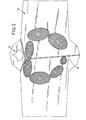
- the various electrodes are numbered 1-7. These electrodes are arranged in a circle and themselves have an elliptical shape, wherein the longitudinal axis of this ellipse is adapted to the course of the intestine portion to be influenced.
- a heating device 11 which can be operated electrically or else may also be formed as a gel that can be heated by microwave heating or it may be a storage body can be used, for example, a stone that is heated accordingly.
- the electrodes are actuated sequentially in their order of 1 to 7, wherein after a passage of current through the electrodes 1 to 7 a short pause can be turned on and then again the electrode sequence is operated again.
- the electrode 1 is the largest, elongated electrode, which is followed in the plan view from the outside as shown in FIG. 1 on the belt or the mat 10 of a slightly smaller elongate electrode 2.
- the electrodes 3 and 4 are again smaller than the electrode 2 and lie on the chord of the theoretical circle.
- the electrode 5 connects, which in turn is designed to be elongated downwards.
- the slightly smaller electrode 6 closes on the circular arc and is followed by an electrode 7, which lies in the region of the rectum.
- the electrodes 1 to 7 according to FIG. 2 come into contact with the upper side of the abdominal wall, preferably with the interposition of a gel or a liquid, in order to ensure good current transmission.
- Each individual electrode is driven for about 4 to 8 seconds, ie successively the electrodes 1 to 7 respectively 4 to 8 seconds. After a pass, there will be a pause, which can be about 5 to 20 seconds, and then a new round will take place.
- both the intensity of the electrodes as well as possibly the duration of the effectiveness of the electrodes is adjustable and can be set individually by the patient.
Landscapes
- Health & Medical Sciences (AREA)
- Animal Behavior & Ethology (AREA)
- Veterinary Medicine (AREA)
- Public Health (AREA)
- General Health & Medical Sciences (AREA)
- Life Sciences & Earth Sciences (AREA)
- Radiology & Medical Imaging (AREA)
- Nuclear Medicine, Radiotherapy & Molecular Imaging (AREA)
- Biomedical Technology (AREA)
- Engineering & Computer Science (AREA)
- Rehabilitation Therapy (AREA)
- Epidemiology (AREA)
- Pain & Pain Management (AREA)
- Physical Education & Sports Medicine (AREA)
- Gastroenterology & Hepatology (AREA)
- Electrotherapy Devices (AREA)
Description
- Die Erfindung bezieht sich auf einen Reizstromstimulator zur Behandlung des Reizdarmsyndroms gemäß dem Oberbegriff des Patentanspruches 1.
- Das Reizdarmsyndrom beschäftigt seit langem die Medizin. Hierbei handelt es sich um eine sogenannte funktionelle Erkrankung des Magen-Darm-Traktes.
- Typisch für ein Reizdarmsyndrom ist, wenn sich die Symptome bei längerer Phase der Entspannung, z. B. im Urlaub, bessern und sich in Zeiten, in denen der Betroffene starkem Streß ausgesetzt ist, verschlimmern. Zu den Symptomen des Reizdarmsyndromes zählen Schmerz, Veränderungen im Stuhlgang, nämlich Verstopfung oder Durchfall sowie geblähter Bauch und auch Schleimabgaben.
- Die Behandlung des Reizdarmsyndroms erfolgt über eine Arzneimitteltherapie, durch Umstellen der Ernährung und/oder durch Selbsthilfe, wobei zu der Selbsthilfe auch Therapieformen zählen, die die Psyche beeinflussen, d. h. Psychotherapie, Hypnose, autogenes Training, Atemübungen, funktionelle Entspannung sowie progressive Muskelrelaxsationen.
- Um eine spezielle Bewegungsaktivität des Darmes zu erreichen, sind Dickdarmmassagen, Atemgymnastik und Bauchpressen bekannt.
- Aus der DE 37 37 250 A1 ist ein Darmmassagegerät bekanntgeworden, bei welchem ein Unwuchtvibrator eingesetzt wird, der durch die Abstimmung der Geschwindigkeit und des Unwuchtgewichtes eine möglichst große Schwingweite erreicht. Hierdurch soll ein Schwingungseffekt erzielt werden, der angeblich aus der Vibrationsfördertechnik bekannt ist.
- Bei vorgegebener und nicht variierbarer Schwingungsintensität soll ein für das Zielorgan spezifisch geformter Vibrationskopf durch mechanische Irritation der Darminnervierung die natürliche Darmperistaltik anregen, wobei sich zu einer Irritationswirkung der durch Selbstanwendung individuelle Druck auf den Darm in Richtung des natürlichen Transportweges des Darminhaltes wünschenswert addiert.
- Das Gerät ist in Hantelform ausgebildet und weist einen am Körper anzuwendenden Vibrationskopf, der einen Schwingungsmotor enthält, und einen gegenüberliegenden Haltekopf auf, der als Batterielager zur manuellen Führung dient.
- Ein solcher "Vibrator" hat sich aber zur Behandlung des Reizdarmsyndroms nicht bewährt.
- Heute ist es bekannt, voraussagbar und gezielt sowie in Leistung und Zeit gesteuert, mit Hilfe von Reizstromstimmulatoren über Hautelektroden einen oder mehrere Nerven zur Auslösung von Aktionspotentialen damit zu einer Reaktion an seinem Erfolgsorgan zu zwingen. Die Reizauslösung, d. h. die Erzeugung eines nervalen Aktionspotentials durch Öffnen der Natriumlonenkanäle der Nervenmembrane erfolgt durch einen negativen Spannungsimpuls, da durch den erzeugten Stromfluß-Ladungsverschiebung eine Depolerisation des Ruhemembran-Potentials erzeugt wird.
- Zum Einsatz kommen heute bei einer Muskelstimulation (d. h. bei einer Reizung mit dem Ziel, eine Kontraktion eines bestimmten Muskels zu erzeugen) monodirektionale (Gleichströme) und bidirektionale (Wechselströme) Impulsströme mit einem steilen Anstieg kurzer Impulszeiten (T kleiner als eine Millisekunde) und Frequenzen von ca. 1 - 60 hz. Im allgemeinen kommen heute zur Muskelstimulation, insbesondere im kosmetischen Bereich, vor allem kleine tragbare Stimulatoren vor, die mit bidirektional asymmetrischen Impulsen arbeiten.
- Eine Vorrichtung zur Stimulation der Bauchmuskeln wird in der US-2002/0058972 A1 beschrieben. Hierbei werden wenigstens drei Elektroden auf einem Träger angeordnet und sollen die Unterleibsmuskeln stimulieren, wobei eine zentrale Elektrode vorgesehen ist, wobei zwei weitere Elektroden jeweils auf gegenüberliegenden Seiten dieser zentralen Elektrode angeordnet werden, so daß durch Aufbringen eines gepulsten Signals durch die zentrale Elektrode und die beiden Seitenelektroden, die Unterleibsmuskeln des zu Behandelnden beeinflußt werden.
- Aus der DE 38 13 838 A1 ist ein Reizstromstimulator nach dem Oberbegriff von Anspruch 1 bekannt. Bei diesem elektromedizinischen Behandlungsgerät mit einer Stromquelle und einem Behandlungsteil sind die Einzelelektroden schachbrettartig angeordnet. Die Felder können sowohl rund als auch eckige Umfangslinien aufweisen. Durch eine solche Anordnung soll beispielsweise eine schneckenförmige Stromabfolge erzeugt werden, wodurch z. B. dem Darmverlauf folgend diese speziellen, bisher durch ständige Kreisbewegungen der Behandlungselektroden herbeigeführten darmanregenden Effekte erzielt werden.
- Bei der Behandlung liegt ein Patient auf einer Basiselektrode auf, die aus mehreren Einzelelektroden bestehen kann. Gegenüberliegend ist die Behandlungselektrode angeordnet, wobei beide Elektrodenarten durch entsprechende Leitungen miteinander verbunden sind.
- Der Erfindung liegt die Aufgabe zugrunde, einen vom Patienten zu tragenden Gürtel vorzuschlagen, der mit Elektroden ausgerüstet ist, die gezielt zum Einsatz zur Behandlung des Reizdarmsyndroms ausgebildet sind, wobei für diesen gezielten Einsatz eine bestimmte Form des Gerätes vorgeschlagen wird.
- Diese der Erfindung zugrundeliegende Aufgabe wird durch die Lehre des Patentanspruches 1 gelöst.
- Vorteilhafte Ausgestaltungen sind in den Unteransprüchen erläutert.
- Somit wird ein Reizstromstimulator vorgeschlagen, bei welchem auf einer flexiblen Trägermatte Elektroden kreisförmig angeordnet sind, wobei die Trägermatte eine elektronische Steuerung trägt, die die einzelnen Elektroden aufeinanderfolgend für 4 bis 8 Sekunden in Tätigkeit setzt.
- Die Anordnung der Elektroden ist so, daß diese der natürlichen Darmlage angepaßt angeordnet sind.
- Es kann zusätzlich ein Heizelement vorgesehen sein, das in dem oberen Bereich des von den Elektroden besetzten Kreises vorgesehen ist und sich damit im wesentlichen im Bereich des Plexus Gastrici bzw. Plerus Solaris befindet. Dieses Heizelement kann als Wärmespeicher ausgebildet sein, beispielsweise ein steinartiger Wärmeträger, kann aber in gleicher Weise elektrisch betrieben werden oder durch ein Gel gebildet werden, das vor Inbetriebnahme der Gesamtanordnung aufgeheizt wird.
- Um die Trägermatte und damit die Wirksamkeit der Elektroden an unterschiedliche Körpergrößen anpassen zu können, ist gemäß einem weiteren Merkmal der Erfindung vorgesehen, daß die Elektrodenanordnung in ihrer Weite einregelbar ist. Dies bezieht sich insbesondere auf die Breitenerstreckung der Elektroden voneinander, d. h. beispielsweise kann die Trägermatte in der Mitte geteilt sein, um nach Öffnung dieser Teilung, beispielsweise eines Reißverschlusses, auseinandergezogen zu werden, um somit die Größenanpassung vornehmen zu können.
- Die eigentliche Trägermatte ist mit Halterungsmitteln ausgerüstet. Diese Halterungsmittel können aus Bänder bestehen oder auch in besonders vorteilhafter Weise aus einem Bügel, wie er bei Röntgenschürzen oder Haushaltschürzen bekannt ist, so daß ein einfaches Festklemmen des Stimulators auf dem Körper des Patienten möglich ist.
- Die Impulszeiten der Elektroden sind einstellbar, ebenso wie die Impulsstärke und weiterhin ist eine Steuerung vorgesehen, die es ermöglicht, daß mehrere aufeinanderfolgende Elektrodendurchgänge einstellbar sind.
- Bei einem bevorzugten Ausführungsbeispiel sind sieben Elektroden vorgesehen. Die Elektroden sind dabei unterschiedlich ausgebildet und weisen elliptische Form auf. Die einzelnen Elektroden werden nacheinander angesteuert, wobei im Ablauf die erste Elektrode elliptisch und relativ groß ausgebildet ist, die von einer kleineren elliptischen Elektrode gefolgt wird. Auf diese beiden Elektroden folgen zwei im wesentlichen nebeneinanderliegende kleinere Elektroden, die auf einer Kreissehne liegen. Im Ansteuerungsablauf folgt auf diese Elektroden eine größere Elektrode, deren Längsachse im wesentlichen quer zur Längsachse der beiden voraufgehenden Elektroden liegt. Um den Kreis zu schließen, folgen zwei kleinere Elektroden, wobei die letzte Elektrode, die im Enddarmbereich liegt, sehr klein ist.
- Die erste Elektrode beginnt nicht mittig, sondern entsprechend der Darmlage versetzt schon auf dem aufsteigenden Bogen des gebildeten theoretischen Kreises.
- Die aufeinanderfolgende Ansteuerung der Elektroden erfolgt derart, daß die beim Patienten unten etwa im Bereich des Blinddarmes liegende rechte Elektrode als erste in Betrieb genommen wird, dann nach kurzer Zeit und Stillsetzen dieser Elektrode die nächstfolgende aufsteigende Elektrode usw. bis das die auf den Patienten aufliegende linke untere Elektrode erreicht ist. Dieser Vorgang wird als ein Durchgang bezeichnet und nach einer Ruhepause kann ein zweiter und weitere Durchgänge erfolgen.
- Jede Elektrode wird etwa 4 bis 8 Sekunden angesteuert und die Pause zwischen den einzelnen Durchgängen, wenn mehrere Durchgänge vorgesehen sind, beträgt etwa 5 - 20 Sekunden.
- Durch die erfindungsgemäße Reizstimulation erfolgt eine Unterstützung der Darmtätigkeit, wobei als wichtiger Nebeneffekt gleichzeitig eine Stärkung der Bauchdecke erreicht wird, wobei diese Bauchdeckenstärkung sich auch wiederum positiv auf die Behandlung des Reizdarmsyndroms auswirkt, also im vorliegenden Fall nicht kosmetische Bedeutung hat.
- Ein Ausführungsbeispiel der Erfindung wird nachfolgend anhand der Zeichnungen erläutert. Die Zeichnung zeigt in
- Fig. 1
- eine Draufsicht auf die Trägermatte des Reizstromstimulators und in
- Fig. 2
- die Unterseite der Matte, die mit dem Patienten in Kontakt kommt.
- In den Zeichnungen ist mit 10 eine Trägermatte aus entsprechendem Werkstoff bezeichnet, in der Elektroden 1 bis 7 angeordnet sind. Diese Trägermatte 10 wird über in der Zeichnung nicht dargestellte Befestigungsmittel am menschlichen Körper so festgelegt, daß die unten liegende Seite, d. h. die Seite gemäß Fig. 2 mit dem menschlichen Körper in Kontakt kommt. Als Befestigungsmittel bieten sich Bänder oder vorzugsweise ein Bügel an, wie er bei Röntgenschürzen bekannt ist.
- Um die Trägermatte 10 den unterschiedlichen menschlichen Größen anzupassen, ist über eine Verbindungseinrichtung 12, beispielsweise ein Reißverschluß oder ein Klettverschluß, die Matte 10 auseinanderziehbar, so daß damit bei dem dargestellten Ausführungsbeispiel die Breite der Matte 10 einstellbar ist.
- In den Zeichnungen sind die verschiedenen Elektroden mit den Zahlen 1 bis 7 versehen. Diese Elektroden sind kreisförmig angeordnet und weisen selbst eine elliptische Form auf, wobei die Längsachse dieser Ellipse dem Verlauf des zu beeinflussenden Darmabschnittes angepaßt ist.
- In den Zeichnungen sind die elektrischen Verbindungsleitungen und die elektronische Steuerung aus Übersichtlichkeitsgründen nicht dargestellt, wohl aber ein Schalter 14, mit dem die Intensität der Elektroden durch den Patienten einstellbar ist.
- Zusätzlich liegt im oberen Bereich der Matte 10 eine Heizeinrichtung 11, die elektrisch betrieben werden kann oder aber auch als Gel ausgebildet sein kann, das durch eine Mikrowellenerwärmung erwärmt werden kann oder auch es kann ein Speicherkörper eingesetzt werden, beispielsweise ein Stein, der entsprechend erwärmt wird.
- Die Elektroden werden in ihrer Reihenfolge 1 bis 7 aufeinanderfolgend betätigt, wobei nach einem Stromdurchgang durch die Elektroden 1 bis 7 eine kurze Pause eingeschaltet werden kann und dann erneut die Elektrodenabfolge wiederum betätigt wird.
- Die Elektrode 1 ist die größte, langgestreckte Elektrode, die bei der Draufsicht von außen gemäß Fig. 1 auf den Gürtel oder die Matte 10 von einer etwas kleineren langgestreckten Elektrode 2 gefolgt wird. Die Elektroden 3 und 4 sind wiederum kleiner als die Elektrode 2 und liegen auf der Sehne des theoretischen Kreises. An die Elektrode 4 schließt sich die Elektrode 5 an, die wiederum langgestreckt ausgebildet nach unten gerichtet ist. Die wiederum etwas kleinere Elektrode 6 schließt sich auf dem Kreisbogen an und wird von einer Elektrode 7 gefolgt, die im Bereich des Enddarmes liegt.
- Beim Einsatz des erfindungsgemäßen Reizstromstimulators kommen die Elektroden 1 bis 7 gemäß Fig. 2 mit der Oberseite der Bauchdecke in Kontakt, vorzugsweise unter Zwischenschaltung eines Gels oder einer Flüssigkeit, um damit eine gute Stromübertragung sicherzustellen.
- Jede einzelne Elektrode wird etwa 4 bis 8 Sekunden angesteuert, d. h. aufeinanderfolgend die Elektroden 1 bis 7 jeweils 4 bis 8 Sekunden. Nach einem Durchgang schließt sich eine Pause an, die etwa 5 bis 20 Sekunden betragen kann und dann erfolgt ein neuer Durchgang.
- An dem in der Zeichnung dargestellten Steuergerät 14 ist sowohl die Intensität der Elektroden wie auch ggf. die Dauer der Wirksamkeit der Elektroden einstellbar und kann vom Patienten individuell eingestellt werden.
Claims (8)
- Reizstromstimulator zur Behandlung des Reizdarmsyndroms mit auf einer flexiblen Trägermatte (10) der natürlichen Darmlage folgend angeordnete Elektroden (1 - 7) mit einer elektronischen Steuerung für eine Aktivierung der Elektroden in einer aufeinanderfolgenden Reihenfolge, dadurch gekennzeichnet, daß bei Verwendung jede Elektrode (1 - 7) 4 - 8 Sek. in Tätigkeit gesetzt wird und die Elektroden (1 - 7) elliptisch ausgebildet sind und auf der Trägermatte (10) mit ihrer langen Achse kreisförmig angeordnet sind, wobei bei Verwendung der obere Bereich des Kreises sich auf einem Köpper eines Patienten im Bereich des Plexus Gastrici und der untere Bereich des Kreises sich im Enddarmbereich befindet und die Ansteuerung der einzelnen Elektroden aufeinanderfolgend bei der im Bereich des Blinddarms liegenden, von vorne gesehen linken Elektrode (1) beginnt und an der im Enddarmbereich angeordneten Elektrode (7) endet.
- Reizstromsimulator nach Anspruch 1, dadurch gekennzeichnet, daß aufeinanderfolgend, beginnend im Bereich des Blinddarmes, zwei große elliptische Elektroden (1, 2), anschließend zwei kleine elliptische Elektroden (3, 4) vorgesehen sind, auf die eine größere Elektrode (5) folgt, an die eine kleinere elliptische Elektrode (6) anschließt, wobei die abschließende Elektrode (7) im Enddarmbereich klein ausgebildet ist.
- Reizstromstimulator nach Anspruch 1 oder 2, gekennzeichnet durch ein Heizelement (11) im elektrodenfreien Bereich des von den Elektroden (1 - 7) besetzten Kreises.
- Reizstromstimulator nach einem oder mehreren der vorhergehenden Ansprüche, dadurch gekennzeichnet, daß die Trägermatte (19) mit Halterungsmittel ausgerüstet ist.
- Reizstromstimulator nach Anspruch 4, dadurch gekennzeichnet, daß als Halterungsmittel ein Bügel eingesetzt ist.
- Reizstromstimulator nach einem oder mehreren der vorhergehenden Ansprüche, dadurch gekennzeichnet, daß mehrere aufeinanderfolgende Elektrodendurchgänge in einem zeitlichen Abstand von 5 - 20 Sek. einstellbar sind.
- Reizstromstimulator nach einem oder mehreren der vorhergehenden Ansprüche, dadurch gekennzeichnet, daß die Impulszeiten der Elektroden (1 - 7) einstellbar sind.
- Reizstromstimulator nach einem oder mehreren der vorhergehenden Ansprüche, dadurch gekennzeichnet, daß die Impulsstärke der Elektroden (1 - 7) einstellbar ist.
Applications Claiming Priority (2)
| Application Number | Priority Date | Filing Date | Title |
|---|---|---|---|
| DE10255571 | 2002-11-28 | ||
| DE10255571A DE10255571B4 (de) | 2002-11-28 | 2002-11-28 | Reizstromstimulator zur Behandlung des Reizdarmsyndroms |
Publications (2)
| Publication Number | Publication Date |
|---|---|
| EP1424097A1 EP1424097A1 (de) | 2004-06-02 |
| EP1424097B1 true EP1424097B1 (de) | 2006-06-21 |
Family
ID=32240498
Family Applications (1)
| Application Number | Title | Priority Date | Filing Date |
|---|---|---|---|
| EP03027107A Expired - Lifetime EP1424097B1 (de) | 2002-11-28 | 2003-11-26 | Reizstromstimulator zur Behandlung des Reizdarmsyndroms |
Country Status (3)
| Country | Link |
|---|---|
| EP (1) | EP1424097B1 (de) |
| AT (1) | ATE330664T1 (de) |
| DE (2) | DE10255571B4 (de) |
Families Citing this family (3)
| Publication number | Priority date | Publication date | Assignee | Title |
|---|---|---|---|---|
| GB0319284D0 (en) * | 2003-08-15 | 2003-09-17 | Isis Innovation | Apparatus and method for stimulation of the human body |
| US8700178B2 (en) | 2005-12-27 | 2014-04-15 | Boston Scientific Neuromodulation Corporation | Stimulator leads and methods for lead fabrication |
| AU2007235178B2 (en) * | 2006-03-31 | 2011-10-06 | Boston Scientific Neuromodulation Corporation | Non-linear electrode array |
Citations (1)
| Publication number | Priority date | Publication date | Assignee | Title |
|---|---|---|---|---|
| DE3813838A1 (de) * | 1987-04-27 | 1989-05-11 | Karl Dr Pallin | Elektromedizinisches behandlungsgeraet mit einer stromquelle u. einem behandlungsteil |
Family Cites Families (6)
| Publication number | Priority date | Publication date | Assignee | Title |
|---|---|---|---|---|
| DE3326429A1 (de) * | 1983-07-22 | 1985-01-31 | Joachim 7500 Karlsruhe Trump-Bär | Vorrichtung fuer kosmetische zwecke zum thermischen behandeln von koerperpartien eines probanden |
| US4676246A (en) * | 1985-02-04 | 1987-06-30 | Tetsuya Korenaga | Low-frequency electrotherapy apparatus |
| DE3514210C1 (de) * | 1985-04-19 | 1986-10-02 | Claus-Dieter Dr.med. 6633 Wadgassen Kopetzky | Vorrichtung zur elektrischen Behandlung von Koerperteilen |
| EP1144045B1 (de) * | 1999-01-11 | 2003-05-21 | BMR Research and Development Limited | Elektrotherapeutisches gerät |
| US20020077688A1 (en) * | 2000-12-15 | 2002-06-20 | Kirkland Thomas C. | Electrode-positioning body garment |
| DE20200685U1 (de) * | 2001-08-17 | 2002-03-28 | van der Hoeven, Martin, San Diego, Calif. | Vorrichtung zur Elektrostimulation von Muskeln |
-
2002
- 2002-11-28 DE DE10255571A patent/DE10255571B4/de not_active Expired - Fee Related
-
2003
- 2003-11-26 DE DE50303929T patent/DE50303929D1/de not_active Expired - Fee Related
- 2003-11-26 EP EP03027107A patent/EP1424097B1/de not_active Expired - Lifetime
- 2003-11-26 AT AT03027107T patent/ATE330664T1/de not_active IP Right Cessation
Patent Citations (1)
| Publication number | Priority date | Publication date | Assignee | Title |
|---|---|---|---|---|
| DE3813838A1 (de) * | 1987-04-27 | 1989-05-11 | Karl Dr Pallin | Elektromedizinisches behandlungsgeraet mit einer stromquelle u. einem behandlungsteil |
Also Published As
| Publication number | Publication date |
|---|---|
| DE50303929D1 (de) | 2006-08-03 |
| EP1424097A1 (de) | 2004-06-02 |
| DE10255571A1 (de) | 2004-06-17 |
| DE10255571B4 (de) | 2008-02-28 |
| ATE330664T1 (de) | 2006-07-15 |
Similar Documents
| Publication | Publication Date | Title |
|---|---|---|
| US20240157139A1 (en) | Stimulation to guide physical therapy | |
| EP2533747B1 (de) | Vorrichtung zur behandlung eines patienten mit vibrations-, tast- und/oder thermoreizen | |
| Beaulieu et al. | Repetitive peripheral magnetic stimulation to reduce pain or improve sensorimotor impairments: A literature review on parameters of application and afferents recruitment | |
| DE102009023855B4 (de) | Vorrichtung zur Nervenreizung mit Magnetfeldimpulsen | |
| EP2675522A2 (de) | Vorrichtung zur reduktion von schmerzen | |
| WO2006118793A3 (en) | Identification of electrodes for nerve stimulation in the treatment of eating disorders | |
| DE102009004011A1 (de) | Verfahren und Vorrichtung zur Stimulierung der Extremitäten zum Bewegungs- und Muskeltraining | |
| ATE448000T1 (de) | Gewichtsverlustvorrichtung | |
| CN102886102A (zh) | 镜像运动神经调制系统 | |
| EP1022034A1 (de) | Verfahren und Vorrichtung zur Stimulation von Muskeln oder Nervengewebe | |
| Börner et al. | The bottom-up approach: non-invasive peripheral neurostimulation methods to treat migraine: a scoping review from the child neurologist's perspective | |
| Laubacher et al. | Power output and fatigue properties using spatially distributed sequential stimulation in a dynamic knee extension task | |
| CH673949A5 (de) | ||
| DE10255571B4 (de) | Reizstromstimulator zur Behandlung des Reizdarmsyndroms | |
| EP2266660B1 (de) | Elektrostimulationsgerät für mehrere Benutzer | |
| DE20218463U1 (de) | Reizstromstimulator zur Behandlung des Reizdarmsyndroms | |
| US11571541B2 (en) | Apparatus and methods of transcranial stimulation to adjust sensory cortical dendritic spine neck membrane potentials for altering consciousness | |
| DE4435308A1 (de) | Massagevorrichtung | |
| Skvortsov et al. | Functional electrical stimulation method: Recommended application parameters | |
| DE102007003565B4 (de) | Vorrichtung zur Reduktion der Synchronisation neuronaler Hirnaktivität sowie dafür geeignete Spule | |
| Arsenidis et al. | A novel electrical muscle stimulation device for neurorehabilitation applications with adaptable parameter optimization using AI algorithms | |
| DE3716816C2 (de) | ||
| DE202015105062U1 (de) | Gerät zur transkutanen elektrischen Stimulation von Muskeln und/oder Nerven am menschlichen Körper | |
| Miller | Neuroscience of swallowing: Strategies in rehabilitation | |
| Bochkezanian | Electrotherapeutic techniques |
Legal Events
| Date | Code | Title | Description |
|---|---|---|---|
| PUAI | Public reference made under article 153(3) epc to a published international application that has entered the european phase |
Free format text: ORIGINAL CODE: 0009012 |
|
| 17P | Request for examination filed |
Effective date: 20040311 |
|
| AK | Designated contracting states |
Kind code of ref document: A1 Designated state(s): AT BE BG CH CY CZ DE DK EE ES FI FR GB GR HU IE IT LI LU MC NL PT RO SE SI SK TR |
|
| AX | Request for extension of the european patent |
Extension state: AL LT LV MK |
|
| AKX | Designation fees paid |
Designated state(s): AT BE BG CH CY CZ DE DK EE ES FI FR GB GR HU IE IT LI LU MC NL PT RO SE SI SK TR |
|
| GRAP | Despatch of communication of intention to grant a patent |
Free format text: ORIGINAL CODE: EPIDOSNIGR1 |
|
| GRAS | Grant fee paid |
Free format text: ORIGINAL CODE: EPIDOSNIGR3 |
|
| GRAA | (expected) grant |
Free format text: ORIGINAL CODE: 0009210 |
|
| AK | Designated contracting states |
Kind code of ref document: B1 Designated state(s): AT BE BG CH CY CZ DE DK EE ES FI FR GB GR HU IE IT LI LU MC NL PT RO SE SI SK TR |
|
| PG25 | Lapsed in a contracting state [announced via postgrant information from national office to epo] |
Ref country code: IT Free format text: LAPSE BECAUSE OF FAILURE TO SUBMIT A TRANSLATION OF THE DESCRIPTION OR TO PAY THE FEE WITHIN THE PRESCRIBED TIME-LIMIT;WARNING: LAPSES OF ITALIAN PATENTS WITH EFFECTIVE DATE BEFORE 2007 MAY HAVE OCCURRED AT ANY TIME BEFORE 2007. THE CORRECT EFFECTIVE DATE MAY BE DIFFERENT FROM THE ONE RECORDED. Effective date: 20060621 Ref country code: RO Free format text: LAPSE BECAUSE OF FAILURE TO SUBMIT A TRANSLATION OF THE DESCRIPTION OR TO PAY THE FEE WITHIN THE PRESCRIBED TIME-LIMIT Effective date: 20060621 Ref country code: FI Free format text: LAPSE BECAUSE OF FAILURE TO SUBMIT A TRANSLATION OF THE DESCRIPTION OR TO PAY THE FEE WITHIN THE PRESCRIBED TIME-LIMIT Effective date: 20060621 Ref country code: CZ Free format text: LAPSE BECAUSE OF FAILURE TO SUBMIT A TRANSLATION OF THE DESCRIPTION OR TO PAY THE FEE WITHIN THE PRESCRIBED TIME-LIMIT Effective date: 20060621 Ref country code: SI Free format text: LAPSE BECAUSE OF FAILURE TO SUBMIT A TRANSLATION OF THE DESCRIPTION OR TO PAY THE FEE WITHIN THE PRESCRIBED TIME-LIMIT Effective date: 20060621 Ref country code: SK Free format text: LAPSE BECAUSE OF FAILURE TO SUBMIT A TRANSLATION OF THE DESCRIPTION OR TO PAY THE FEE WITHIN THE PRESCRIBED TIME-LIMIT Effective date: 20060621 Ref country code: IE Free format text: LAPSE BECAUSE OF FAILURE TO SUBMIT A TRANSLATION OF THE DESCRIPTION OR TO PAY THE FEE WITHIN THE PRESCRIBED TIME-LIMIT Effective date: 20060621 |
|
| REG | Reference to a national code |
Ref country code: GB Ref legal event code: FG4D Free format text: NOT ENGLISH |
|
| REG | Reference to a national code |
Ref country code: CH Ref legal event code: EP |
|
| REG | Reference to a national code |
Ref country code: IE Ref legal event code: FG4D Free format text: LANGUAGE OF EP DOCUMENT: GERMAN |
|
| REG | Reference to a national code |
Ref country code: CH Ref legal event code: NV Representative=s name: BRAUNPAT BRAUN EDER AG |
|
| REF | Corresponds to: |
Ref document number: 50303929 Country of ref document: DE Date of ref document: 20060803 Kind code of ref document: P |
|
| PG25 | Lapsed in a contracting state [announced via postgrant information from national office to epo] |
Ref country code: SE Free format text: LAPSE BECAUSE OF FAILURE TO SUBMIT A TRANSLATION OF THE DESCRIPTION OR TO PAY THE FEE WITHIN THE PRESCRIBED TIME-LIMIT Effective date: 20060921 Ref country code: DK Free format text: LAPSE BECAUSE OF FAILURE TO SUBMIT A TRANSLATION OF THE DESCRIPTION OR TO PAY THE FEE WITHIN THE PRESCRIBED TIME-LIMIT Effective date: 20060921 |
|
| PG25 | Lapsed in a contracting state [announced via postgrant information from national office to epo] |
Ref country code: ES Free format text: LAPSE BECAUSE OF FAILURE TO SUBMIT A TRANSLATION OF THE DESCRIPTION OR TO PAY THE FEE WITHIN THE PRESCRIBED TIME-LIMIT Effective date: 20061002 |
|
| GBT | Gb: translation of ep patent filed (gb section 77(6)(a)/1977) |
Effective date: 20060913 |
|
| PG25 | Lapsed in a contracting state [announced via postgrant information from national office to epo] |
Ref country code: PT Free format text: LAPSE BECAUSE OF FAILURE TO SUBMIT A TRANSLATION OF THE DESCRIPTION OR TO PAY THE FEE WITHIN THE PRESCRIBED TIME-LIMIT Effective date: 20061121 |
|
| PG25 | Lapsed in a contracting state [announced via postgrant information from national office to epo] |
Ref country code: MC Free format text: LAPSE BECAUSE OF NON-PAYMENT OF DUE FEES Effective date: 20061130 |
|
| ET | Fr: translation filed | ||
| REG | Reference to a national code |
Ref country code: IE Ref legal event code: FD4D |
|
| PLBE | No opposition filed within time limit |
Free format text: ORIGINAL CODE: 0009261 |
|
| STAA | Information on the status of an ep patent application or granted ep patent |
Free format text: STATUS: NO OPPOSITION FILED WITHIN TIME LIMIT |
|
| 26N | No opposition filed |
Effective date: 20070322 |
|
| PGFP | Annual fee paid to national office [announced via postgrant information from national office to epo] |
Ref country code: BE Payment date: 20070411 Year of fee payment: 4 |
|
| PGFP | Annual fee paid to national office [announced via postgrant information from national office to epo] |
Ref country code: NL Payment date: 20071129 Year of fee payment: 5 |
|
| PGFP | Annual fee paid to national office [announced via postgrant information from national office to epo] |
Ref country code: AT Payment date: 20071220 Year of fee payment: 5 Ref country code: CH Payment date: 20071129 Year of fee payment: 5 |
|
| PG25 | Lapsed in a contracting state [announced via postgrant information from national office to epo] |
Ref country code: GR Free format text: LAPSE BECAUSE OF FAILURE TO SUBMIT A TRANSLATION OF THE DESCRIPTION OR TO PAY THE FEE WITHIN THE PRESCRIBED TIME-LIMIT Effective date: 20060922 |
|
| PGFP | Annual fee paid to national office [announced via postgrant information from national office to epo] |
Ref country code: FR Payment date: 20071130 Year of fee payment: 5 Ref country code: GB Payment date: 20071129 Year of fee payment: 5 |
|
| BERE | Be: lapsed |
Owner name: CHOO, GEORG Effective date: 20071130 |
|
| PG25 | Lapsed in a contracting state [announced via postgrant information from national office to epo] |
Ref country code: EE Free format text: LAPSE BECAUSE OF FAILURE TO SUBMIT A TRANSLATION OF THE DESCRIPTION OR TO PAY THE FEE WITHIN THE PRESCRIBED TIME-LIMIT Effective date: 20060621 Ref country code: BG Free format text: LAPSE BECAUSE OF FAILURE TO SUBMIT A TRANSLATION OF THE DESCRIPTION OR TO PAY THE FEE WITHIN THE PRESCRIBED TIME-LIMIT Effective date: 20060921 |
|
| PGFP | Annual fee paid to national office [announced via postgrant information from national office to epo] |
Ref country code: TR Payment date: 20071207 Year of fee payment: 5 |
|
| PG25 | Lapsed in a contracting state [announced via postgrant information from national office to epo] |
Ref country code: LU Free format text: LAPSE BECAUSE OF NON-PAYMENT OF DUE FEES Effective date: 20061126 Ref country code: HU Free format text: LAPSE BECAUSE OF FAILURE TO SUBMIT A TRANSLATION OF THE DESCRIPTION OR TO PAY THE FEE WITHIN THE PRESCRIBED TIME-LIMIT Effective date: 20061222 |
|
| PG25 | Lapsed in a contracting state [announced via postgrant information from national office to epo] |
Ref country code: BE Free format text: LAPSE BECAUSE OF NON-PAYMENT OF DUE FEES Effective date: 20071130 |
|
| PG25 | Lapsed in a contracting state [announced via postgrant information from national office to epo] |
Ref country code: CY Free format text: LAPSE BECAUSE OF FAILURE TO SUBMIT A TRANSLATION OF THE DESCRIPTION OR TO PAY THE FEE WITHIN THE PRESCRIBED TIME-LIMIT Effective date: 20060621 |
|
| PGFP | Annual fee paid to national office [announced via postgrant information from national office to epo] |
Ref country code: DE Payment date: 20090210 Year of fee payment: 6 |
|
| REG | Reference to a national code |
Ref country code: CH Ref legal event code: PL |
|
| GBPC | Gb: european patent ceased through non-payment of renewal fee |
Effective date: 20081126 |
|
| PG25 | Lapsed in a contracting state [announced via postgrant information from national office to epo] |
Ref country code: NL Free format text: LAPSE BECAUSE OF NON-PAYMENT OF DUE FEES Effective date: 20090601 |
|
| NLV4 | Nl: lapsed or anulled due to non-payment of the annual fee |
Effective date: 20090601 |
|
| PG25 | Lapsed in a contracting state [announced via postgrant information from national office to epo] |
Ref country code: AT Free format text: LAPSE BECAUSE OF NON-PAYMENT OF DUE FEES Effective date: 20081126 |
|
| REG | Reference to a national code |
Ref country code: FR Ref legal event code: ST Effective date: 20090731 |
|
| PG25 | Lapsed in a contracting state [announced via postgrant information from national office to epo] |
Ref country code: CH Free format text: LAPSE BECAUSE OF NON-PAYMENT OF DUE FEES Effective date: 20081130 Ref country code: LI Free format text: LAPSE BECAUSE OF NON-PAYMENT OF DUE FEES Effective date: 20081130 |
|
| PG25 | Lapsed in a contracting state [announced via postgrant information from national office to epo] |
Ref country code: GB Free format text: LAPSE BECAUSE OF NON-PAYMENT OF DUE FEES Effective date: 20081126 |
|
| PG25 | Lapsed in a contracting state [announced via postgrant information from national office to epo] |
Ref country code: DE Free format text: LAPSE BECAUSE OF NON-PAYMENT OF DUE FEES Effective date: 20100601 |
|
| PG25 | Lapsed in a contracting state [announced via postgrant information from national office to epo] |
Ref country code: FR Free format text: LAPSE BECAUSE OF NON-PAYMENT OF DUE FEES Effective date: 20081130 Ref country code: TR Free format text: LAPSE BECAUSE OF NON-PAYMENT OF DUE FEES Effective date: 20100921 |
|
| PG25 | Lapsed in a contracting state [announced via postgrant information from national office to epo] |
Ref country code: TR Free format text: LAPSE BECAUSE OF NON-PAYMENT OF DUE FEES Effective date: 20081126 |