EP1424247B1 - Sicherheitsvorrichtung - Google Patents
Sicherheitsvorrichtung Download PDFInfo
- Publication number
- EP1424247B1 EP1424247B1 EP03257480A EP03257480A EP1424247B1 EP 1424247 B1 EP1424247 B1 EP 1424247B1 EP 03257480 A EP03257480 A EP 03257480A EP 03257480 A EP03257480 A EP 03257480A EP 1424247 B1 EP1424247 B1 EP 1424247B1
- Authority
- EP
- European Patent Office
- Prior art keywords
- deformable
- mounting bracket
- lifting unit
- arrangement according
- lugs
- Prior art date
- Legal status (The legal status is an assumption and is not a legal conclusion. Google has not performed a legal analysis and makes no representation as to the accuracy of the status listed.)
- Expired - Lifetime
Links
- 239000002184 metal Substances 0.000 claims description 7
- 239000000463 material Substances 0.000 claims description 3
- 238000007789 sealing Methods 0.000 description 6
- 239000004744 fabric Substances 0.000 description 4
- 230000002093 peripheral effect Effects 0.000 description 4
- 239000011324 bead Substances 0.000 description 3
- 230000000994 depressogenic effect Effects 0.000 description 3
- 230000007246 mechanism Effects 0.000 description 3
- 238000000034 method Methods 0.000 description 2
- 230000000717 retained effect Effects 0.000 description 2
- 229910000831 Steel Inorganic materials 0.000 description 1
- 230000000694 effects Effects 0.000 description 1
- 238000004519 manufacturing process Methods 0.000 description 1
- 239000010959 steel Substances 0.000 description 1
Images







Classifications
-
- B—PERFORMING OPERATIONS; TRANSPORTING
- B60—VEHICLES IN GENERAL
- B60R—VEHICLES, VEHICLE FITTINGS, OR VEHICLE PARTS, NOT OTHERWISE PROVIDED FOR
- B60R21/00—Arrangements or fittings on vehicles for protecting or preventing injuries to occupants or pedestrians in case of accidents or other traffic risks
- B60R21/34—Protecting non-occupants of a vehicle, e.g. pedestrians
- B60R21/38—Protecting non-occupants of a vehicle, e.g. pedestrians using means for lifting bonnets
-
- F—MECHANICAL ENGINEERING; LIGHTING; HEATING; WEAPONS; BLASTING
- F15—FLUID-PRESSURE ACTUATORS; HYDRAULICS OR PNEUMATICS IN GENERAL
- F15B—SYSTEMS ACTING BY MEANS OF FLUIDS IN GENERAL; FLUID-PRESSURE ACTUATORS, e.g. SERVOMOTORS; DETAILS OF FLUID-PRESSURE SYSTEMS, NOT OTHERWISE PROVIDED FOR
- F15B15/00—Fluid-actuated devices for displacing a member from one position to another; Gearing associated therewith
- F15B15/19—Pyrotechnical actuators
-
- B—PERFORMING OPERATIONS; TRANSPORTING
- B60—VEHICLES IN GENERAL
- B60R—VEHICLES, VEHICLE FITTINGS, OR VEHICLE PARTS, NOT OTHERWISE PROVIDED FOR
- B60R21/00—Arrangements or fittings on vehicles for protecting or preventing injuries to occupants or pedestrians in case of accidents or other traffic risks
- B60R21/34—Protecting non-occupants of a vehicle, e.g. pedestrians
- B60R2021/343—Protecting non-occupants of a vehicle, e.g. pedestrians using deformable body panel, bodywork or components
Definitions
- THE PRESENT INVENTION relates to a safety arrangement and more particularly relates to a safety arrangement provided in a motor vehicle adapted to lift the rear part of the hood or bonnet of the vehicle in response to an impact or accident situation involving a pedestrian.
- JP 11310157 discloses an impact absorbing device for a motor vehicle hood which comprises an actuator configured to lift the rear part of the hood.
- the actuator is coupled to a hinge mechanism in order to provide a desired lifting characteristic.
- US 6,415,882 discloses device for raising the hood of a motor vehicle in the event of an accident in order to increase the amount of space between the hood and the engine according to the preamble of claim 1.
- This arrangement uses an actuator and is arranged so that, upon actuation of the actuator, a pivot pin 16 moves along the slot, the arrangement being configured so that in the event of subsequent downward impact to the bonnet, the sides of the slot are deformed around the pivot pin.
- DE19721565 discloses another safety arrangement for lifting the hood of a motor vehicle, the arrangement being located at the front of the hood and being configured so as to allow a person manually to open the hood in order to gain access to the engine below it.
- the present invention seeks to provide an improved safety arrangement.
- a safety arrangement incorporating a lifting unit, the lifting unit including a first element to be mounted in position in a motor vehicle and a second element, movable to a predetermined limited extent relative to the first element to increase the overall length of the lifting unit, characterised in that one of said elements is associated with a deformable member to be operatively positioned between the said one of the elements and part of the vehicle so that, in use, the momentum gained by the second element during its movement towards said limited extent is applied to the deformable member when the second element meets the limit of its movement to deform the member and hence increase the overall length of the lifting unit.
- the first element is engaged by a mounting bracket to mount the unit in position, the mounting bracket being the deformable element and being formed at least partly of a deformable material such that, in use, the momentum causes the mounting bracket to deform.
- the mounting bracket is formed of a deformable metal and includes an initially planar region to which the first element is fixed and two lugs at opposed ends of that planar region, the lugs being provided with mounting apertures or recesses to mount the bracket in position, part of the mounting bracket adjacent the lugs being deformable.
- the mounting bracket has an initial planar portion of generally rectangular form, the lugs being provided at opposed ends of the rectangular planar portion and folded to lie under the rectangular planar portion, parts of the rectangular planar portion overlying the lugs being cut-away to provided access to the mounting apertures or recesses provided in the lugs.
- the deformable member is mounted to the movable element, between the movable element and a cap, there being a co-operating unit to be mounted on the vehicle, the cap and co-operating unit being engageable on actuation of the safety arrangement.
- the deformable element is in the form of a cup-shaped element, the side-wall of the cup-shaped element being a deformable side-wall.
- the first element is an outer cylinder and the second element is a piston element movable relative to the cylinder.
- the second element may tilt relative t the first element when the second element has moved relative to the first element.
- the second element is connected to the first element by means of an inflatable sleeve.
- the second element is connected to the first element by means of an inflatable bellows.
- the mounting bracket is formed of deformable metal and includes an initially planar region to which the first element is fixed and two lugs at opposed ends of the planar region, the lugs being provided with mounting apertures or recesses to mount the bracket in position, part of the mounting bracket adjacent the lugs being deformable.
- the mounting element has an initial planar portion of generally rectangular form, the lugs being provided at opposed ends of the rectangular planar portion and being folded to lie under the rectangular planar portion, parts of the rectangular planar portion overlying the lugs being cut away to provide access to the mounting apertures or recesses provided in the lugs.
- the first element is an outer cylinder and the second element is a piston element moveable relative tot he cylinder.
- the piston element is a tubular piston.
- the mounting bracket is provided at the bottom of the outer cylinder.
- the mounting bracket is provided at the top of the outer cylinder.
- the lower end of the outer cylinder is provided with a gas generator housing, the gas generator housing having an inner guide tube extending upwardly within the outer cylinder, there being a tubular piston surrounding the guide tube and located within the outer cylinder.
- the second element may tilt relative to the first element when the second element projects from the outer element.
- the arrangement to move the second element includes a gas generator to be actuated in response to an accident situation.
- a lifting unit 1 comprising a first element in the form of an outer cylinder 2 which telescopically receives an inner element 3 in the form of a piston which may be in the form of the second cylinder.
- the outer cylinder 2 is provided, at one end thereof, with a gas generator 4 adapted to generate gas in an appropriate accident situation.
- the inner element 3 may move to a predetermined limited extent relative to the outer cylinder 2 when the gas generator 4 generates gas.
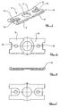
- the lifting unit 1 is mounted in position by means of a mounting bracket 5, the mounting bracket 5 being shown more clearly in Figures 4 to 7.
- the mounting bracket is operatively positioned between the outer cylinder 2 and the motor vehicle.
- the mounting bracket 5 is formed of a sheet of material, for example sheet steel, which is plastically deformable.
- the mounting bracket 5 has a main initially horizontal portion 6 provided with a central aperture 7, the aperture 7 being adapted to engage part of the lifting unit 1 between the outer cylinder 2 and the gas generator 4.
- the main planar region 6 is substantially rectangular, and at each end is provided with a folded tab 8, 9, the tabs being folded inwardly to lie underneath the main planar region 6. Parts of the planar region 10, 11 overlying the inwardly and underfolded tabs 8, 9 are cut away to reveal mounting apertures 12, 13 formed in the tabs.
- the sheet metal where the tabs 8, 9 are folded, it is not folded in a sharp crease, but instead is folded in a "roll" such as the roll 14.
- the mounting bracket 5 is initially mounted in position on the lifting unit 1 with the aperture 7 receiving part of the outer cylinder 2 in the region where the gas generator 4 is connected to the rest of the cylinder 2.
- Mounting bolts, such as the bolts 15, 16 as shown in Figure 1 pass through the cutaway regions 10, 11 and through the apertures 12, 13 provided in the tabs 8, 9 to secure the mounting bracket 5 to a motor vehicle.
- the lifting unit 1 can be mounted in position, for example, beneath the hood or bonnet of the vehicle.
- the upper part of the inner element 2 of the lifting unit 1 may be located immediately beneath the rear part of the hood or bonnet.
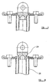
- the gas generator 4 In response to a signal from an appropriate sensor the gas generator 4 generates gas causing the inner element 3 of the lifting unit to rise, as shown in Figure 2, with the inner element extending telescopically out of the outer cylinder 3 to a predetermined limited extent, so that the overall length (or in other words the overall height) of the lifting unit 1 increase. This will serve to lift the rear part of the hood or bonnet.
- the inner element 3 moves so it gains momentum and, when the inner element 3 meets the limit of its movement relative to the cylinder 2, that momentum is imparted to the main cylinder 2.
- the momentum causes the bracket 5 to deform plastically so that the initially planar portion 6 assumes a "bridge" or arched configuration, as shown most clearly in Figure 3.
- the mounting bracket 5 may be deformed, with the main cylinder moving downwardly, absorbing energy.
- the mounting bracket 5 Whilst in the embodiment described with reference to Figure 1 to 7 the mounting bracket 5 is provided almost at the lowermost end of the lifting unit, in an alternative embodiment, as shown in Figure 8 to 12, the mounting bracket may be provided almost at the top of the lifting unit.
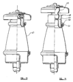
- a mounting bracket 5 of the type described above, is utilised to support the upper end of a first element in the form of an outer cylinder 20.
- the lower end of the outer cylinder 20 supports a housing 21, the housing 21 defining a chamber 22 which is dimensioned to receive a gas generator.
- a cap 23 is provided to retain the gas generator in position.
- Formed integrally with the housing 21 is an inner guide tube 24 which extends axially upwardly within the cylinder 20.
- the guide tube 24 terminates, at its upper end, with a gas outlet aperture 25.
- the guide tube 24 is received within the interior of a second element in the form of a tubular piston 26.
- the tubular piston 26 is of hollow cylindrical form. At its lowermost end the outer wall of the cylindrical piston 26 is provided with an annular piston head 27, the outer periphery of the piston head incorporating a resilient sealing ring 28, such that the piston head 27 is a sliding sealing fit within the outer cylinder 20.
- tubular piston 26 At its uppermost end the tubular piston 26 is sealed by an end plug 29.
- the plug 29 is provided with an upstanding lug 30 defining a horizontal aperture 31.
- a pivot pin may be received through the aperture 31 and part of the hood or bonnet may be pivotally mounted on the pivot pin.
- the sealing plug 29 not only seals the upper end of the tubular piston 26, but also effectively seals the upper end of the outer cylinder 20, in a region where the wall of the cylinder is swaged inwardly to be received in the aperture 7 of the planar region 6 of the mounting bracket 5.
- the plug 29 is held securely and firmly in position, ensuring that an adequate pivotal mounting is provided for the hood or bonnet.
- the tubular piston 26 will continue to move vertically until the piston head 27 engages the inwardly swaged upper end of the outer cylinder 20. This engagement defines a predetermined limit to the extent of movement of the tubular piston 26 relative to the outer cylinder 20.
- the tubular piston 26 can move no further relative to the outer cylinder 20 but the momentum that was imparted to the tubular piston 26 by the gas will be transferred to the outer cylinder 20 and will cause the mounting bracket 5 to deform plastically, in the manner described above with reference to the embodiment of Figure 1 to 7.
- the entire outer cylinder 20 will rise slightly from its initial position, meaning that the sealing plug 29 will also be lifted by a small extra amount. Again the effective overall length (or height) of the lifting unit has been increased.
- the gas pressure is maintained in the outer cylinder by the engagement of the piston head 27 sealingly with the interior of the outer cylinder 20.
- the axis of the tubular piston 26 may be slightly offset from the axis of the outer cylinder 20. This may facilitate the opening of the hood or bonnet since the hood or bonnet is effectively pivoting about the front latch which normally secures the hood or bonnet in the closed position, with the rear part of the hood or bonnet effecting a virtual pivotal movement.
- bracket 5 may re-deform back towards its initial position, again whilst absorbing energy.
- the lifting unit is of a telescopic nature, having an outer cylinder and an inner element telescopically received within the outer cylinder, it is to be understood that the invention is not limited to lifting units of this particular type, and is applicable to lifting units which incorporate an inflatable sleeve or inflated bellows.
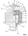
- a first element 40 in the form of a base housing is provided.
- the first element defines a housing of cup-like form having a planar base wall 41 surrounded by a peripheral upstanding side-wall 42.
- the base wall 41 carries, at a central position, a gas generator 43 which extends upwardly into the cup-like housing 40.
- the peripheral side-wall 42 has an enlarged upper lip 44 which defines a recess 45. Retained within the recess 45 is a bead 46 provided at one end of a conical inflatable sleeve 47 that may be formed of fabric similar to that, for example, used in the manufacture of an air-bag.
- a second element 48 is provided, the second element 48 being a movable element, which is movable, to a predetermined limited extent, relative to the first element 40.
- the movable element 48 has a cylindrical outer side-wall 49 of lesser diameter than the peripheral side-wall 42.
- Formed on the exterior of the side-wall 49 is a radially outwardly directed projection 50 which defines a recess 51.
- Retained within the recess 51 is a bead 52 provided at the other end of the sleeve 47.
- a bell-shaped insert 53 Contained within the cylindrical wall 49, at the lower end of the cylindrical wall, is a bell-shaped insert 53, configured to overlie part of the gas generator 43 when the movable element is in a first position, as shown in Figure 12, in which the movable element 48 is contained substantially within the cup-like housing 40.
- the mouth of the bell-shaped insert 53 is secured to the inner part of the cylindrical wall 49.
- the upper-most part of the bell-shaped insert 53 is provided with an upwardly extending projection 54.
- a circular base 55 of a deformable cup-like element 56 Connected to the projection 54 is a circular base 55 of a deformable cup-like element 56, the element 56 having a deformable side-wall 57 which, in an initial condition as shown in Figure 12, is deformed to form sinuous or bellows-like folds.
- the deformable element 56 has the upper part of the side-wall 57 thereof connected, by means of a connecting clip 58, to a closure cap 59 which initially closes the cup-like housing.
- the closure cap 59 thus has a depending side-wall 60, the depending side-wall 60 terminating with an enlarged lip 61 which is a snap-fitting over the radial projection 44 provided on the side-wall 42 of the first element 40.
- the cap 59 is provided with an upper part 62 defining a central depressed region 63.
- the lifting unit is to be mounted in a motor vehicle beneath the hood or bonnet of the vehicle.
- the first element 40 may be received within an appropriate recess provided for that purpose within the motor vehicle.
- a co-operating unit 64 is provided to be mounted on the hood or bonnet.
- the co-operating unit comprises a housing 65 which contains a depending pin 66, the pin 66 being co-aligned with the depressed region 63 provided in the upper part 62 of the cap 59.
- the lifting unit in the initial condition of the lifting unit, the lifting unit is located beneath the co-operating unit 64 and spaced therefrom.
- gas is generated by the gas generator 43 and is injected into the interior of the bell-like insert 53 contained within the cylindrical wall 49 of the movable element 48.
- the movable element 48 thus moves upwardly, moving the inflatable sleeve 47 from an initial folded condition, in which the folds of the sleeve lie between the cylindrical outer wall of the movable element 48 and the peripheral side-wall 42 of the first element 40, to an extended position in which the movable element 48 is moved to a predetermined limited extent above the first element 40.
- Movement of the movable element 48 is thus terminated but, due to momentum, the cover 62 and the co-operating unit 64 (which is secured to the hood or bonnet of the motor vehicle), continue to move upwardly, plastically deforming the side-wall 57 of the deformable cup-like element 56.
- the cap 62 moves further upwardly, as shown in Figure 14, relative to the movable element 48, effectively increasing the overall length (height) of the lifting unit. If a very severe downward force is applied to the hood or bonnet whilst the inflatable sleeve 47 remains inflated, the deformable side-wall 57 may further deform, lowering the hood or bonnet, and absorbing energy.
- FIGS 15 to 17 illustrate yet another embodiment of the invention, but in this embodiment the lifting unit incorporates a bellows.
- the bellows may be of fabric or may be of plastically deformable metal.
- a mounting bracket equivalent to the mounting bracket 5 is utilised.
- a lifting unit comprises a first fixed element 70.
- the first fixed element 70 has a cylindrical side-wall 71 defining an inner chamber, and a base 72, the base carrying a gas generator 73 which projects into the inner chamber.
- the first element 70 is mounted, by means of a mounting bracket 74 in position in a motor vehicle.
- the mounting bracket 74 is directly equivalent to the mounting bracket 5 described above and will not be re-described here.
- the bracket 74 is operatively positioned between the fixed element 70 and the motor vehicle.
- the bellows may be formed of fabric or may be formed of metal.
- the lower end of the bellows is sealed 76 to the outer part of the cylindrical wall 71.
- the upper end of the bellows 75 is connected to a movable element 77 in the form of a substantially planar disc.
- the planar disc 77 initially rests on top of the cylindrical side-wall 71.
- the disc 77 is provided with an upwardly extending centrally located pin 78.
- the pin is configured to mate engagingly with a co-operating element 79 to be mounted on part of a motor vehicle immediately above the described lifter unit.
- bracket 74 would be able to move downwardly, whilst absorbing energy.
- a first fixed element 80 is provided, the element defining a cylindrical side-wall 81 and a base 82.
- the base 82 carries a gas generator 83 which projects upwardly into a cavity defined by the side-wall 81.
- the first element 80 is intended to be fixed in position within a motor vehicle and may be received within a mounting cup 84 which, itself, can be secured to the vehicle.
- a bellows 85 which may be of fabric, or which may be of metal, surrounds the cylindrical side-wall 81, the lower end of the bellows being sealed, by a seal 86 to a lower part of the cylindrical side-wall 81.
- the bellows 85 extend upwardly above the cylindrical side-wall 81, surrounding a second movable element 86 which is of cup-like form having a base 87 and a side-wall 88.
- the upper-most part of the bellows is sealed by means of a seal 89 to part of the side-wall 88.
- a central part of the base of the movable element 86 is provided with an upstanding projection 90.
- the projection 90 engages the base 91 of a cup-shaped deformable element 92, the deformable element 92 having a deformable side-wall 93 which is shown initially in a concertina folded condition.
- the folded side-wall 93 is connected, by means of a connecting clip 94 to a covering cap 95, the covering cap 95 having a planar upper part 96 surrounded by a depending side-wall 97, the depending side-wall 97 having, at its lower end, a bead 98 which forms a snap-fastening with a recess provided for that purpose on the side-wall 86 of the second movable element.
- the cap is provided with a central depressed region 99 which is to receive a pin 100 of a co-operating element 101, similar to that of Figure 12.
- gas from the gas generator is injected into the cavity defmed by the side-wall 81, causing the movable element 86 to be moved upwardly, extending the bellows 85.
- the movable element 86 will move upwardly to the limit of movement defined by the bellows.
- the bellows prevent further upward movement of the movable element 86, due to momentum the deformable side-wall 93 of the deformable element 92 will deform, permitting the co-operating unit 101 to move further upwardly to the position shown in Figure 20.
- the deformable element may be deformed downwardly if a sufficiently large force is applied to the hood or bonnet lifted by the lifting unit.
Landscapes
- Engineering & Computer Science (AREA)
- Mechanical Engineering (AREA)
- Chemical & Material Sciences (AREA)
- Analytical Chemistry (AREA)
- Physics & Mathematics (AREA)
- Fluid Mechanics (AREA)
- General Engineering & Computer Science (AREA)
- Superstructure Of Vehicle (AREA)
- Feeding, Discharge, Calcimining, Fusing, And Gas-Generation Devices (AREA)
- Control Of Combustion (AREA)
- Air Bags (AREA)
- Electrical Discharge Machining, Electrochemical Machining, And Combined Machining (AREA)
Claims (10)
- Sicherheitseinrichtung, wobei die Sicherheitseinrichtung eine Hebeeinheit (1) aufweist, wobei die Hebeeinheit (1) ein erstes Element (2), das an einem Ort in einem Motorfahrzeug zu befestigen ist, und ein zweites Element (3), das in einem vorbestimmten begrenzten Ausmaß relativ zu dem ersten Element (2) bewegbar ist, um die Gesamtlänge der Hebeeinheit (1) zu erhöhen, aufweist, und wobei eines der genannten Elemente (2, 3) mit einem deformierbaren Element (5) verbunden ist, das wirkungsmäßig zwischen dem einen der genannten Elemente (2, 3) und einem Teil des Fahrzeugs anzuordnen ist, dadurch gekennzeichnet, daß während der Verwendung der von dem zweiten Element (3) erreichte Impuls während dessen Bewegung in Richtung des begrenzten Ausmaßes auf das deformierbare Element (5) einwirkt, wenn das zweite Element (3) die Grenze seiner Bewegung erreicht, um das Element (5) zu verformen und dadurch die Gesamtlänge der Hebeeinheit (1) zu erhöhen.
- Sicherheitseinrichtung nach Anspruch 1, dadurch gekennzeichnet, daß das erste Element (2) mit einem Montagearm (5) in Eingriff steht, um die Einheit (1) an ihrem Ort zu befestigen, der Montagearm (5) das deformierbare Element ist und mindestens abschnittsweise aus einem deformierbaren Material besteht, so daß während der Verwendung der Impuls eine Deformierung des Montagearms (5) bewirkt.
- Einrichtung nach Anspruch 2, dadurch gekennzeichnet, daß der Montagearm (5) aus einem deformierbaren Metall gebildet ist und einen im Ausgangszustand ebenen Bereich (6) aufweist, an dem das erste Element (2) befestigt ist, und zwei Laschen (8, 9) an gegenüberliegenden Enden dieses ebenen Bereichs, wobei die Laschen mit Montageöffnungen (12, 13) oder Vertiefungen versehen sind, um den Arm (5) an seinem Ort zu befestigen, wobei ein Abschnitt des Montagearms benachbart zu den Laschen deformierbar ist.
- Einrichtung nach Anspruch 3, dadurch gekennzeichnet, daß der Montagearm einen im Ausgangszustand ebenen Abschnitt (6) von im wesentlichen rechtwinkliger Form aufweist, wobei die Laschen (8, 9) an gegenüberliegenden Enden des rechtwinkligen ebenen Abschnitts (6) vorgesehen sind und gefaltet sind, um unter dem rechtwinkligen ebenen Abschnitt (6) zu liegen, wobei Teile (10, 11) des rechtwinkligen ebenen Abschnitts (6), die über den Laschen (8, 9) liegen, ausgeschnitten sind, um einen Zugang zu den Montageöffnungen (12, 13) oder Vertiefungen, die über den Laschen (8, 9) vorgesehen sind, bereitzustellen.
- Sicherheitseinrichtung nach Anspruch 1, dadurch gekennzeichnet, daß das deformierbare Element (5) an dem zweiten Element (48) gehalten ist, wobei zwischen dem zweiten Element (48) und einer Kappe (59) eine Mitwirkungseinheit (64) angeordnet ist, die auf dem Fahrzeug anzubringen ist, wobei die Kappe (59) und die Mitwirkungseinheit (64) bei Betätigung der Sicherheitseinrichtung miteinander in Eingriff bringbar sind.
- Sicherheitseinrichtung nach Anspruch 5, dadurch gekennzeichnet, daß das deformierbare Element (56) die Form eines tassenförmigen Elements aufweist, wobei die Seitenwand (57) des tassenförmigen Elements eine deformierbare Seitenwand (57) ist.
- Einrichtung nach einem der vorangehenden Ansprüche, dadurch gekennzeichnet, daß das erste Element (2) ein äußerer Zylinder und das zweite Element (3) ein Kolbenelement ist, das relativ zu dem Zylinder bewegbar ist.
- Einrichtung nach Anspruch 7, dadurch gekennzeichnet, daß sich das zweite Element (3) relativ zu dem ersten Element (2) neigen kann, wenn sich das zweite Element (3) relativ zu dem ersten Element (2) bewegt hat.
- Einrichtung nach einem der Ansprüche 1 bis 6, dadurch gekennzeichnet, daß das zweite Element (48) mit dem ersten Element mittels einer aufblasbaren Manschette (47) verbunden ist.
- Einrichtung nach einem der Ansprüche 1 bis 6, dadurch gekennzeichnet, daß das zweite Element (77) mit dem ersten Element (70) mittels eines aufblasbaren Faltenbalgs (75) verbunden ist.
Applications Claiming Priority (2)
| Application Number | Priority Date | Filing Date | Title |
|---|---|---|---|
| GB0227805 | 2002-11-28 | ||
| GB0227805A GB2395692B (en) | 2002-11-28 | 2002-11-28 | Improvements in or relating to a safety arrangement |
Publications (2)
| Publication Number | Publication Date |
|---|---|
| EP1424247A1 EP1424247A1 (de) | 2004-06-02 |
| EP1424247B1 true EP1424247B1 (de) | 2006-08-30 |
Family
ID=9948717
Family Applications (1)
| Application Number | Title | Priority Date | Filing Date |
|---|---|---|---|
| EP03257480A Expired - Lifetime EP1424247B1 (de) | 2002-11-28 | 2003-11-27 | Sicherheitsvorrichtung |
Country Status (4)
| Country | Link |
|---|---|
| EP (1) | EP1424247B1 (de) |
| AT (1) | ATE337948T1 (de) |
| DE (1) | DE60307962T2 (de) |
| GB (1) | GB2395692B (de) |
Families Citing this family (12)
| Publication number | Priority date | Publication date | Assignee | Title |
|---|---|---|---|---|
| EP1658205B1 (de) * | 2003-06-06 | 2010-11-03 | ACTS-Advanced Car Technology Systems GmbH & Co.KG | Vorrichtung und verfahren zum anheben der fronthaube eines kraftfahrzeugs bei einer fussgängerkollision |
| FR2884475B1 (fr) * | 2005-04-14 | 2007-06-08 | Peugeot Citroen Automobiles Sa | Butee retractable au choc pour vehicule automobile |
| DE102005024357A1 (de) * | 2005-05-27 | 2006-11-30 | Bayerische Motoren Werke Ag | Anordnung einer Frontklappe an einem Fahrzeug |
| JP4908909B2 (ja) | 2006-04-27 | 2012-04-04 | 日本発條株式会社 | フードを持ち上げるアクチュエータ機構 |
| EP2679451B1 (de) * | 2012-10-19 | 2014-12-10 | Metalsa Automotive GmbH | Antriebseinheit mit Gasgenerator |
| US9944252B2 (en) | 2014-02-10 | 2018-04-17 | Tk Holdings Inc. | Pressurized gas-powered actuator and sealed piston rod therefor |
| JP2016022795A (ja) * | 2014-07-17 | 2016-02-08 | タカタ株式会社 | 車両用ポップアップフード装置及び車両 |
| JP6672929B2 (ja) * | 2016-01-20 | 2020-03-25 | Joyson Safety Systems Japan株式会社 | 車両用ポップアップフード装置 |
| US10145393B2 (en) * | 2016-06-17 | 2018-12-04 | Joyson Safety Systems Acquisition Llc | Linear actuator |
| DE102016219474B4 (de) * | 2016-09-09 | 2019-07-04 | Joyson Safety Systems Germany Gmbh | Aktuator und Verfahren zur Herstellung eines Aktuators |
| JP7110998B2 (ja) | 2019-01-16 | 2022-08-02 | 豊田合成株式会社 | アクチュエータ |
| EP4289685B1 (de) * | 2022-06-08 | 2025-04-30 | Autoliv Development AB | Sicherheitsvorrichtung in einem fahrzeug |
Family Cites Families (8)
| Publication number | Priority date | Publication date | Assignee | Title |
|---|---|---|---|---|
| DE19721565B4 (de) * | 1996-05-31 | 2006-10-05 | Volkswagen Ag | Sicherheitseinrichtung an einem Fahrzeug zum Schutz von Fußgängern |
| JP3506904B2 (ja) * | 1998-04-03 | 2004-03-15 | 本田技研工業株式会社 | 車両のフード用ヒンジ |
| JPH11310157A (ja) * | 1998-04-27 | 1999-11-09 | Honda Motor Co Ltd | 車両用フードの衝撃吸収装置 |
| US6520276B2 (en) * | 2000-07-19 | 2003-02-18 | Honda Giken Kogyo Kabushiki Kaisha | Vehicle hood apparatus |
| US6554093B2 (en) * | 2000-07-19 | 2003-04-29 | Honda Giken Kogyo Kabushiki Kaisha | Vehicular hood device |
| EP1277629A1 (de) * | 2001-07-05 | 2003-01-22 | Ford Global Technologies, Inc. | Energieaufnehmende Einrichtung |
| US6415882B1 (en) * | 2001-11-05 | 2002-07-09 | Ford Global Technologies, Inc. | Deployable hinge for pedestrian protection vehicle hood |
| DE10214602B4 (de) * | 2002-04-03 | 2004-04-15 | Daimlerchrysler Ag | Aktive Fronthaube |
-
2002
- 2002-11-28 GB GB0227805A patent/GB2395692B/en not_active Expired - Fee Related
-
2003
- 2003-11-27 EP EP03257480A patent/EP1424247B1/de not_active Expired - Lifetime
- 2003-11-27 DE DE60307962T patent/DE60307962T2/de not_active Expired - Lifetime
- 2003-11-27 AT AT03257480T patent/ATE337948T1/de not_active IP Right Cessation
Also Published As
| Publication number | Publication date |
|---|---|
| GB2395692B (en) | 2005-11-09 |
| GB0227805D0 (en) | 2003-01-08 |
| GB2395692A (en) | 2004-06-02 |
| ATE337948T1 (de) | 2006-09-15 |
| DE60307962D1 (de) | 2006-10-12 |
| EP1424247A1 (de) | 2004-06-02 |
| DE60307962T2 (de) | 2007-09-06 |
Similar Documents
| Publication | Publication Date | Title |
|---|---|---|
| EP1565356B1 (de) | Verbesserungen für eine sicherheitsanordnung oder diesebetreffend | |
| EP1323597B1 (de) | Fronthaube mit energieabsorbierender Einrichtung im Fall eines aufprallenden Körpers | |
| EP1424247A1 (de) | Sicherheitsvorrichtung | |
| US7159685B2 (en) | Safety arrangement for a vehicle | |
| US7246677B2 (en) | Safety arrangement for a vehicle | |
| US7793978B2 (en) | Constrained airbag deployment using an external tether | |
| JP2014511986A (ja) | フード持ち上げ装置 | |
| JP3321577B2 (ja) | 自動車の乗員の安全性を確保する方法及びそれを実施するエアーバッグモジュール | |
| US6435549B1 (en) | Air bag device | |
| US7401809B2 (en) | Airbag device | |
| EP1948485B1 (de) | Fahrzeugsicherheitsvorrichtung | |
| JP3804066B2 (ja) | フロントボンネット用の作動装置及びフロントボンネットを作動させる方法 | |
| JP2007522024A (ja) | 安全装置 | |
| GB2373219A (en) | Safety arrangement | |
| GB2475474A (en) | A throttled inflatable lifter for a vehicle bonnet | |
| GB2387578A (en) | Impact responsive means for raising a vehicle bonnet | |
| GB2389818A (en) | A motor vehicle bonnet lifting device | |
| JP2025518877A (ja) | 車両内の安全装置 | |
| JP2008110703A (ja) | 歩行者保護装置 | |
| KR20010035889A (ko) | 루프 에어백이 장착된 자동차의 프론트 시트의 구조 |
Legal Events
| Date | Code | Title | Description |
|---|---|---|---|
| PUAI | Public reference made under article 153(3) epc to a published international application that has entered the european phase |
Free format text: ORIGINAL CODE: 0009012 |
|
| AK | Designated contracting states |
Kind code of ref document: A1 Designated state(s): AT BE BG CH CY CZ DE DK EE ES FI FR GB GR HU IE IT LI LU MC NL PT RO SE SI SK TR |
|
| AX | Request for extension of the european patent |
Extension state: AL LT LV MK |
|
| 17P | Request for examination filed |
Effective date: 20041201 |
|
| AKX | Designation fees paid |
Designated state(s): AT BE BG CH CY CZ DE DK EE ES FI FR GB GR HU IE IT LI LU MC NL PT RO SE SI SK TR |
|
| 17Q | First examination report despatched |
Effective date: 20050621 |
|
| GRAP | Despatch of communication of intention to grant a patent |
Free format text: ORIGINAL CODE: EPIDOSNIGR1 |
|
| GRAS | Grant fee paid |
Free format text: ORIGINAL CODE: EPIDOSNIGR3 |
|
| GRAA | (expected) grant |
Free format text: ORIGINAL CODE: 0009210 |
|
| AK | Designated contracting states |
Kind code of ref document: B1 Designated state(s): AT BE BG CH CY CZ DE DK EE ES FI FR GR HU IE IT LI LU MC NL PT RO SE SI SK TR |
|
| PG25 | Lapsed in a contracting state [announced via postgrant information from national office to epo] |
Ref country code: IT Free format text: LAPSE BECAUSE OF FAILURE TO SUBMIT A TRANSLATION OF THE DESCRIPTION OR TO PAY THE FEE WITHIN THE PRESCRIBED TIME-LIMIT;WARNING: LAPSES OF ITALIAN PATENTS WITH EFFECTIVE DATE BEFORE 2007 MAY HAVE OCCURRED AT ANY TIME BEFORE 2007. THE CORRECT EFFECTIVE DATE MAY BE DIFFERENT FROM THE ONE RECORDED. Effective date: 20060830 Ref country code: CH Free format text: LAPSE BECAUSE OF FAILURE TO SUBMIT A TRANSLATION OF THE DESCRIPTION OR TO PAY THE FEE WITHIN THE PRESCRIBED TIME-LIMIT Effective date: 20060830 Ref country code: LI Free format text: LAPSE BECAUSE OF FAILURE TO SUBMIT A TRANSLATION OF THE DESCRIPTION OR TO PAY THE FEE WITHIN THE PRESCRIBED TIME-LIMIT Effective date: 20060830 Ref country code: SK Free format text: LAPSE BECAUSE OF FAILURE TO SUBMIT A TRANSLATION OF THE DESCRIPTION OR TO PAY THE FEE WITHIN THE PRESCRIBED TIME-LIMIT Effective date: 20060830 Ref country code: BE Free format text: LAPSE BECAUSE OF FAILURE TO SUBMIT A TRANSLATION OF THE DESCRIPTION OR TO PAY THE FEE WITHIN THE PRESCRIBED TIME-LIMIT Effective date: 20060830 Ref country code: FI Free format text: LAPSE BECAUSE OF FAILURE TO SUBMIT A TRANSLATION OF THE DESCRIPTION OR TO PAY THE FEE WITHIN THE PRESCRIBED TIME-LIMIT Effective date: 20060830 Ref country code: SI Free format text: LAPSE BECAUSE OF FAILURE TO SUBMIT A TRANSLATION OF THE DESCRIPTION OR TO PAY THE FEE WITHIN THE PRESCRIBED TIME-LIMIT Effective date: 20060830 Ref country code: RO Free format text: LAPSE BECAUSE OF FAILURE TO SUBMIT A TRANSLATION OF THE DESCRIPTION OR TO PAY THE FEE WITHIN THE PRESCRIBED TIME-LIMIT Effective date: 20060830 Ref country code: AT Free format text: LAPSE BECAUSE OF FAILURE TO SUBMIT A TRANSLATION OF THE DESCRIPTION OR TO PAY THE FEE WITHIN THE PRESCRIBED TIME-LIMIT Effective date: 20060830 Ref country code: NL Free format text: LAPSE BECAUSE OF FAILURE TO SUBMIT A TRANSLATION OF THE DESCRIPTION OR TO PAY THE FEE WITHIN THE PRESCRIBED TIME-LIMIT Effective date: 20060830 Ref country code: CZ Free format text: LAPSE BECAUSE OF FAILURE TO SUBMIT A TRANSLATION OF THE DESCRIPTION OR TO PAY THE FEE WITHIN THE PRESCRIBED TIME-LIMIT Effective date: 20060830 |
|
| REG | Reference to a national code |
Ref country code: CH Ref legal event code: EP |
|
| REG | Reference to a national code |
Ref country code: IE Ref legal event code: FG4D |
|
| REF | Corresponds to: |
Ref document number: 60307962 Country of ref document: DE Date of ref document: 20061012 Kind code of ref document: P |
|
| PG25 | Lapsed in a contracting state [announced via postgrant information from national office to epo] |
Ref country code: IE Free format text: LAPSE BECAUSE OF NON-PAYMENT OF DUE FEES Effective date: 20061127 |
|
| PG25 | Lapsed in a contracting state [announced via postgrant information from national office to epo] |
Ref country code: MC Free format text: LAPSE BECAUSE OF NON-PAYMENT OF DUE FEES Effective date: 20061130 Ref country code: DK Free format text: LAPSE BECAUSE OF FAILURE TO SUBMIT A TRANSLATION OF THE DESCRIPTION OR TO PAY THE FEE WITHIN THE PRESCRIBED TIME-LIMIT Effective date: 20061130 Ref country code: BG Free format text: LAPSE BECAUSE OF FAILURE TO SUBMIT A TRANSLATION OF THE DESCRIPTION OR TO PAY THE FEE WITHIN THE PRESCRIBED TIME-LIMIT Effective date: 20061130 Ref country code: SE Free format text: LAPSE BECAUSE OF FAILURE TO SUBMIT A TRANSLATION OF THE DESCRIPTION OR TO PAY THE FEE WITHIN THE PRESCRIBED TIME-LIMIT Effective date: 20061130 |
|
| PG25 | Lapsed in a contracting state [announced via postgrant information from national office to epo] |
Ref country code: ES Free format text: LAPSE BECAUSE OF FAILURE TO SUBMIT A TRANSLATION OF THE DESCRIPTION OR TO PAY THE FEE WITHIN THE PRESCRIBED TIME-LIMIT Effective date: 20061211 |
|
| PG25 | Lapsed in a contracting state [announced via postgrant information from national office to epo] |
Ref country code: PT Free format text: LAPSE BECAUSE OF FAILURE TO SUBMIT A TRANSLATION OF THE DESCRIPTION OR TO PAY THE FEE WITHIN THE PRESCRIBED TIME-LIMIT Effective date: 20070212 |
|
| NLV1 | Nl: lapsed or annulled due to failure to fulfill the requirements of art. 29p and 29m of the patents act | ||
| EN | Fr: translation not filed | ||
| PLBE | No opposition filed within time limit |
Free format text: ORIGINAL CODE: 0009261 |
|
| STAA | Information on the status of an ep patent application or granted ep patent |
Free format text: STATUS: NO OPPOSITION FILED WITHIN TIME LIMIT |
|
| 26N | No opposition filed |
Effective date: 20070531 |
|
| PG25 | Lapsed in a contracting state [announced via postgrant information from national office to epo] |
Ref country code: GR Free format text: LAPSE BECAUSE OF FAILURE TO SUBMIT A TRANSLATION OF THE DESCRIPTION OR TO PAY THE FEE WITHIN THE PRESCRIBED TIME-LIMIT Effective date: 20061201 Ref country code: FR Free format text: LAPSE BECAUSE OF FAILURE TO SUBMIT A TRANSLATION OF THE DESCRIPTION OR TO PAY THE FEE WITHIN THE PRESCRIBED TIME-LIMIT Effective date: 20070511 |
|
| PG25 | Lapsed in a contracting state [announced via postgrant information from national office to epo] |
Ref country code: EE Free format text: LAPSE BECAUSE OF FAILURE TO SUBMIT A TRANSLATION OF THE DESCRIPTION OR TO PAY THE FEE WITHIN THE PRESCRIBED TIME-LIMIT Effective date: 20060830 |
|
| PG25 | Lapsed in a contracting state [announced via postgrant information from national office to epo] |
Ref country code: HU Free format text: LAPSE BECAUSE OF FAILURE TO SUBMIT A TRANSLATION OF THE DESCRIPTION OR TO PAY THE FEE WITHIN THE PRESCRIBED TIME-LIMIT Effective date: 20070301 Ref country code: LU Free format text: LAPSE BECAUSE OF NON-PAYMENT OF DUE FEES Effective date: 20061127 Ref country code: TR Free format text: LAPSE BECAUSE OF FAILURE TO SUBMIT A TRANSLATION OF THE DESCRIPTION OR TO PAY THE FEE WITHIN THE PRESCRIBED TIME-LIMIT Effective date: 20060830 |
|
| REG | Reference to a national code |
Ref country code: CH Ref legal event code: PK Free format text: DAS PATENT WURDE INFOLGE NICHTEINTRITT DER WIRKUNG FUER CH/LI AUF DAS ERTEILUNGSDATUM ZURUECK GELOESCHT. Ref country code: CH Ref legal event code: PL |
|
| PG25 | Lapsed in a contracting state [announced via postgrant information from national office to epo] |
Ref country code: FR Free format text: LAPSE BECAUSE OF FAILURE TO SUBMIT A TRANSLATION OF THE DESCRIPTION OR TO PAY THE FEE WITHIN THE PRESCRIBED TIME-LIMIT Effective date: 20060830 Ref country code: CY Free format text: LAPSE BECAUSE OF FAILURE TO SUBMIT A TRANSLATION OF THE DESCRIPTION OR TO PAY THE FEE WITHIN THE PRESCRIBED TIME-LIMIT Effective date: 20060830 |
|
| PGFP | Annual fee paid to national office [announced via postgrant information from national office to epo] |
Ref country code: DE Payment date: 20181130 Year of fee payment: 16 |
|
| REG | Reference to a national code |
Ref country code: DE Ref legal event code: R119 Ref document number: 60307962 Country of ref document: DE |
|
| PG25 | Lapsed in a contracting state [announced via postgrant information from national office to epo] |
Ref country code: DE Free format text: LAPSE BECAUSE OF NON-PAYMENT OF DUE FEES Effective date: 20200603 |