EP1424262A2 - Elektrische Servolenkung - Google Patents
Elektrische Servolenkung Download PDFInfo
- Publication number
- EP1424262A2 EP1424262A2 EP03027394A EP03027394A EP1424262A2 EP 1424262 A2 EP1424262 A2 EP 1424262A2 EP 03027394 A EP03027394 A EP 03027394A EP 03027394 A EP03027394 A EP 03027394A EP 1424262 A2 EP1424262 A2 EP 1424262A2
- Authority
- EP
- European Patent Office
- Prior art keywords
- steering
- electric power
- shaft
- worm
- backlash
- Prior art date
- Legal status (The legal status is an assumption and is not a legal conclusion. Google has not performed a legal analysis and makes no representation as to the accuracy of the status listed.)
- Granted
Links
- 230000007935 neutral effect Effects 0.000 claims abstract description 14
- 230000003247 decreasing effect Effects 0.000 claims description 2
- 238000005096 rolling process Methods 0.000 description 21
- 230000007246 mechanism Effects 0.000 description 15
- 229920003002 synthetic resin Polymers 0.000 description 6
- 239000000057 synthetic resin Substances 0.000 description 6
- 229910052751 metal Inorganic materials 0.000 description 5
- 239000002184 metal Substances 0.000 description 5
- 230000009467 reduction Effects 0.000 description 5
- 230000008859 change Effects 0.000 description 4
- 239000000314 lubricant Substances 0.000 description 4
- 230000005540 biological transmission Effects 0.000 description 3
- XEEYBQQBJWHFJM-UHFFFAOYSA-N Iron Chemical compound [Fe] XEEYBQQBJWHFJM-UHFFFAOYSA-N 0.000 description 2
- 238000004519 manufacturing process Methods 0.000 description 2
- 230000002093 peripheral effect Effects 0.000 description 2
- 229910000838 Al alloy Inorganic materials 0.000 description 1
- RYGMFSIKBFXOCR-UHFFFAOYSA-N Copper Chemical compound [Cu] RYGMFSIKBFXOCR-UHFFFAOYSA-N 0.000 description 1
- 238000010521 absorption reaction Methods 0.000 description 1
- 229910052802 copper Inorganic materials 0.000 description 1
- 239000010949 copper Substances 0.000 description 1
- 238000006073 displacement reaction Methods 0.000 description 1
- 229910052742 iron Inorganic materials 0.000 description 1
- 230000004048 modification Effects 0.000 description 1
- 238000012986 modification Methods 0.000 description 1
- 231100000989 no adverse effect Toxicity 0.000 description 1
- 230000004044 response Effects 0.000 description 1
- 230000001629 suppression Effects 0.000 description 1
- 230000008961 swelling Effects 0.000 description 1
Images



Classifications
-
- B—PERFORMING OPERATIONS; TRANSPORTING
- B62—LAND VEHICLES FOR TRAVELLING OTHERWISE THAN ON RAILS
- B62D—MOTOR VEHICLES; TRAILERS
- B62D5/00—Power-assisted or power-driven steering
- B62D5/04—Power-assisted or power-driven steering electrical, e.g. using an electric servo-motor connected to, or forming part of, the steering gear
-
- F—MECHANICAL ENGINEERING; LIGHTING; HEATING; WEAPONS; BLASTING
- F16—ENGINEERING ELEMENTS AND UNITS; GENERAL MEASURES FOR PRODUCING AND MAINTAINING EFFECTIVE FUNCTIONING OF MACHINES OR INSTALLATIONS; THERMAL INSULATION IN GENERAL
- F16H—GEARING
- F16H25/00—Gearings comprising primarily only cams, cam-followers and screw-and-nut mechanisms
- F16H25/18—Gearings comprising primarily only cams, cam-followers and screw-and-nut mechanisms for conveying or interconverting oscillating or reciprocating motions
- F16H25/20—Screw mechanisms
- F16H25/24—Elements essential to such mechanisms, e.g. screws, nuts
-
- B—PERFORMING OPERATIONS; TRANSPORTING
- B62—LAND VEHICLES FOR TRAVELLING OTHERWISE THAN ON RAILS
- B62D—MOTOR VEHICLES; TRAILERS
- B62D5/00—Power-assisted or power-driven steering
- B62D5/04—Power-assisted or power-driven steering electrical, e.g. using an electric servo-motor connected to, or forming part of, the steering gear
- B62D5/0409—Electric motor acting on the steering column
-
- F—MECHANICAL ENGINEERING; LIGHTING; HEATING; WEAPONS; BLASTING
- F16—ENGINEERING ELEMENTS AND UNITS; GENERAL MEASURES FOR PRODUCING AND MAINTAINING EFFECTIVE FUNCTIONING OF MACHINES OR INSTALLATIONS; THERMAL INSULATION IN GENERAL
- F16H—GEARING
- F16H57/00—General details of gearing
- F16H57/12—Arrangements for adjusting or for taking-up backlash not provided for elsewhere
-
- Y—GENERAL TAGGING OF NEW TECHNOLOGICAL DEVELOPMENTS; GENERAL TAGGING OF CROSS-SECTIONAL TECHNOLOGIES SPANNING OVER SEVERAL SECTIONS OF THE IPC; TECHNICAL SUBJECTS COVERED BY FORMER USPC CROSS-REFERENCE ART COLLECTIONS [XRACs] AND DIGESTS
- Y10—TECHNICAL SUBJECTS COVERED BY FORMER USPC
- Y10T—TECHNICAL SUBJECTS COVERED BY FORMER US CLASSIFICATION
- Y10T74/00—Machine element or mechanism
- Y10T74/19—Gearing
- Y10T74/19623—Backlash take-up
-
- Y—GENERAL TAGGING OF NEW TECHNOLOGICAL DEVELOPMENTS; GENERAL TAGGING OF CROSS-SECTIONAL TECHNOLOGIES SPANNING OVER SEVERAL SECTIONS OF THE IPC; TECHNICAL SUBJECTS COVERED BY FORMER USPC CROSS-REFERENCE ART COLLECTIONS [XRACs] AND DIGESTS
- Y10—TECHNICAL SUBJECTS COVERED BY FORMER USPC
- Y10T—TECHNICAL SUBJECTS COVERED BY FORMER US CLASSIFICATION
- Y10T74/00—Machine element or mechanism
- Y10T74/19—Gearing
- Y10T74/19642—Directly cooperating gears
- Y10T74/19698—Spiral
- Y10T74/19828—Worm
-
- Y—GENERAL TAGGING OF NEW TECHNOLOGICAL DEVELOPMENTS; GENERAL TAGGING OF CROSS-SECTIONAL TECHNOLOGIES SPANNING OVER SEVERAL SECTIONS OF THE IPC; TECHNICAL SUBJECTS COVERED BY FORMER USPC CROSS-REFERENCE ART COLLECTIONS [XRACs] AND DIGESTS
- Y10—TECHNICAL SUBJECTS COVERED BY FORMER USPC
- Y10T—TECHNICAL SUBJECTS COVERED BY FORMER US CLASSIFICATION
- Y10T74/00—Machine element or mechanism
- Y10T74/19—Gearing
- Y10T74/1987—Rotary bodies
- Y10T74/19893—Sectional
- Y10T74/19898—Backlash take-up
-
- Y—GENERAL TAGGING OF NEW TECHNOLOGICAL DEVELOPMENTS; GENERAL TAGGING OF CROSS-SECTIONAL TECHNOLOGIES SPANNING OVER SEVERAL SECTIONS OF THE IPC; TECHNICAL SUBJECTS COVERED BY FORMER USPC CROSS-REFERENCE ART COLLECTIONS [XRACs] AND DIGESTS
- Y10—TECHNICAL SUBJECTS COVERED BY FORMER USPC
- Y10T—TECHNICAL SUBJECTS COVERED BY FORMER US CLASSIFICATION
- Y10T74/00—Machine element or mechanism
- Y10T74/19—Gearing
- Y10T74/19949—Teeth
- Y10T74/19953—Worm and helical
Definitions
- the present invention relates to an electric power steering apparatus using a motor as a source of a steering assisting force.
- a related automotive electric power steering apparatus controls output rotation of an electric motor according to steering torque loaded on the steering member.
- a rotation of the electric motor is transmitted to a steering mechanism through a reduction gear mechanism to thereby assist the steering mechanism in response to a rotation operation of the steering member. Consequently, labor burden imposed on a driver for steering is reduced.
- Another related electric power steering apparatus which uses a mechanism having, for example, a worm and a worm wheel as the reduction mechanism, has been provided (for instance, JP-A-2000-43739).
- this related electric power steering apparatus has encountered a problem of, for example, rattling noises due to a reverse input from tires when an automobile travels straight on a bad road, such as a gravel road. Conversely, in a case where backlash is set to be small so as to suppress rattling sounds, transmission resistance increases. Thus, this related electric power steering apparatus has a problem in that when the state of the automobile is changed from a cornering state to a straight traveling state, the return of a steering wheel is worsened.
- an object of the invention is to provide an electric power steering apparatus enabled to realize a small increase in resistance torque and also enabled to suppress noise generation.
- an electric power steering apparatus (hereunder referred to as a first electric power steering apparatus of the invention) , which is adapted to transmit power, which is supplied from an electric motor for assisting steering, through a driving gear and a driven gear.
- backlash between the driving gear and the driven gear is set at least in a neighborhood region of a steering neutral position to be smaller than that in a remaining region.
- Inventors of the invention direct attention to the facts that even when a vehicle travels on a bad road, noises are hard to be produced in a case where each of gears transmits power from an electric motor during steering, and that noises are easily produced in a case where each of the gears does not transmit power from the electricmotor during the vehicle straight travels on a bad road.
- the backlash between the driving gear and the driven gear is set to be a relatively large value according to which the suppression of resistance torque can be achieved.
- the backlash between the driving gear and the driven gear is set to be a relatively small value. Consequently, the first electric power steering apparatus of the invention prevents noises from being produced during straight traveling.
- the driven gear includes a bias portion formed by biasing a part of an outer periphery of teeth in a direction in which the backlash is decreased.
- the second electric power steering apparatus of the invention can reduce increase in the resistance torque and suppress production of noises by utilizing a simple configuration in which a bias portion is provided in a part of outer peripheral portions of teeth.
- the driving gear is constituted by a worm.
- the driven gear is constituted by a worm wheel.
- the position of a shaft center of the worm is offset in an axial direction of the worm wheel by a predetermined offset amount.
- the third electric power steering apparatus of the invention can reduce increase in the resistance torque and suppress production of noises by utilizing a simple configuration in which the position of the shaft center of the worm is offset in an axial direction of the worm wheel by a predetermined offset amount.
- FIG. 1 is a schematic sectional view illustrating a primary part of an electric power steering apparatus that is an embodiment of the invention.
- a first steering shaft 2 serving as an input shaft, to which a steering wheel 1 is attached, is coaxially connected through a torsion bar 4 to a second steering shaft 3 serving as an output shaft to be connected to a steering mechanism (not shown), such as a rack-and-pinion mechanism.
- a steering mechanism such as a rack-and-pinion mechanism.
- a housing 5 for supporting the first steering shaft 2 and the second steering shaft 3 is made of, for example, an aluminum alloy, and attached to an automobile body (not shown).
- the housing 5 comprises a sensor housing 6 and a gear housing 7, which are fitted to each other.
- the gear housing 7 is cylindrically shaped and has an annular edge portion 7a, which is provided at the top thereof and fitted to an annular step portion 6a provided on the bottom outer periphery of the sensor housing 6.
- the gear housing 7 accommodates a worm gear mechanism 8 serving as a reduction mechanism.
- the sensor housing 6 accommodates a torque sensor 9 and a control circuit board 10.
- a reduction gear 50 is constituted by accommodating the worm gear mechanism 8 in the gear housing 7.
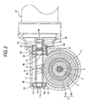
- the worm gear mechanism 8 has a copper worm shaft (or worm) 11, which is connected to a rotating shaft 32 of an electric motor M through a joint mechanism, for instance, a spline joint 33, as shown in FIG. 2, and also has a worm wheel 12 that meshes with this worm shaft 11, that is enabled to rotate integrally with an axially middle portion of the second steering shaft 3, as shown in FIG. 1, and that is restrained from moving in an axial direction.
- the worm shaft 11 is rotatably supported in the gear housing 7 through a pair of bearings.
- the worm wheel 12 has an annular metal core 12a integrally rotatably connected to the second steering shaft and also has a synthetic resin member 12b that surrounds the metal core 12a and that has teeth provided on an outer peripheral surface portion thereof.
- the metal core 12a is inserted into a mold, for example, when the synthetic resinmember 12b is resin-molded.
- the metal core 12a and the molded synthetic resin member 12b are integrally rotatably connected to each other.
- lubricant is filled in a region including at least a part A in which the worm shaft 11 and the worm wheel 12 mesh with each other. That is, lubricant may be filled only in the part A . Alternatively, lubricant may be filled in the part A and the entire rim part of the worm shaft 11. Alternatively, lubricant may be filled in the entire gear housing 7.
- the second steering shaft 3 is supported by first and second rolling bearings 13 and 14 placed in such a way as to sandwich the worm wheel from above and below in an axial direction.
- An outer ring 15 of the first rolling bearing 13 is fitted into and held in a bearing holding hole 16 provided in a cylindrical projection 6b that is formed at the bottom of the sensor housing 6.
- the top surface of the outer ring 15 of the first rolling bearing 13 abuts against an annular step portion 17 and is restrained from upwardly and axially moving toward the sensor housing 6.
- an inner ring 18 of the first rolling bearing 13 is interference-fitted to the second steering shaft 3.
- the bottom surface of the inner ring 18 abuts against the top surface of the metal core 12a of the worm wheel 12.
- An outer ring 19 of the second rolling bearing 14 is fitted into and held in a bearing holding hole 20 provided in the gear housing 7.
- the bottom surface of the outer ring 19 of the second rolling bearing 14 abuts against an annular step portion 21 and is restrained from downwardly and axially moving toward the gear housing 7.
- An inner ring 22 of the second rolling bearing 14 is integrally rotatably attached to the second steering shaft 3 in such a way as to be restrained fromperforming axially relative displacement.
- the inner ring 22 is held between a step portion 23 and a nut 24 screwed onto a threaded portion of the second steering shaft 3.
- the torsion bar 4 penetrates through the first steering shaft 2 and the second steering shaft 3.
- the top end 4a of the torsion bar 4 is integrally rotatably connected to the first steering shaft 2 by a connecting pin 25, while the bottom end 4b thereof is integrally rotatably connected to the second steering shaft 3 by a connecting pin 26.
- the bottom end of the second steering shaft 3 is connected to the steering mechanism, such as the rack-and-pinion mechanism, through an intermediate shaft (not shown).
- the connecting pin 25 connects a third steering shaft 27, which is coaxially disposed with the first steering shaft 2, and the first steering shaft 2 in such a way as to integrally rotate therewith.
- the third steering shaft 27 penetrates through a tube 28 of a steering column.
- An upper part of the fist steering shaft 2 is rotatably supported on the sensor housing 6 through a third rolling bearing 29 constituted by, for instance, a needle roller bearing.
- a diametrically reduced portion 30 provided at a lower part of the first steering shaft 2 is fitted in a hole 31 formed in an upper part of the second steering shaft by providing predeterminedplay in the direction of relative rotation between the first steering shaft 2 and the second steering shaft 3 so as to restrict the relative rotation therebetween within a predetermined range.
- the worm shaft 11 is rotatably supported by each of a fourth rolling bearing 34 and a fifth rolling bearing 35, which are held by the gear housing 7.
- Each of the fourth rolling bearing 34 and the fifth rolling bearing 35 is constituted by, for example, a ball bearing.
- Each of an inner ring 36 of the fourth rolling bearing 34 and an inner ring 37 of the fifth rolling bearing 35 is fitted into an associated one of narrow portions of the worm shaft 11.
- Each of an outer ring 38 of the fourth rolling bearing 34 and an outer ring 39 of the fifth rolling bearing 35 is held in bearing holding holes 40 and 41 of the gear housing 7, respectively.
- the gear housing 7 includes a part 7b radially facing a part of a circumferential surface of the worm shaft 11.
- the outer ring 38 of the fourth rolling bearing 34 supporting one of end portions 11a of the worm shaft 11 abuts against the step portion 42 of the gear housing 7 and is positioned thereat.
- the inner ring 36 of the fourth rolling bearing 34 abuts against a positioning step portion of the worm shaft 11.
- the worm shaft 11 is restrained from moving toward the other end portion 11b of the worm shaft 11.
- the inner ring 37 of the fifth rolling bearing 35 which supports a neighborhood portion of the other end portion (that is, the joint-side end portion) 11b of the worm shaft 11, abuts against the positioning step portion 44 of the worm shaft 11.
- the outer ring 39 of the fifth rolling bearing 35 is pushed toward the fourth rollingbearing 34 by a pre-pressure adjustment screw member 45.
- the screw member 45 applies a pre-pressure to a pair of rolling bearings 34 and 35 by being screwed into a screw hole 46 formed in the gear housing 7.
- the screw member 45 performs the axial positioning of the worm shaft 11.
- Reference numeral 47 designates a lock nut to be engaged with the screw member 45 so as to fix the screw member 45 after the pre-pressure is adjusted.
- a bias portion 61 biased outwardly and radially is formed in a part of the profile of each of teeth 60.
- the radius R of a pitch circle of the worm wheel 12 which is indicated by a dot-and-dash line, has a value R2 at a central portion of a part 62 corresponding to the bias portion 61 and is larger than a value R1 at the remaining part (that is, R2>R1).
- a gearing radius RA of the worm wheel 12 corresponds to a radius R of a pitch circle of the worm wheel 12 at a gearing part A in which the worm wheel 12 meshes with the worm shaft 11.
- the gearing radius RA has an intermediate value between the values R1 and R2 (R1 ⁇ R ⁇ R2).
- FIG. 5A is a graph showing the relation between a steering angle ⁇ (that is, an angle of rotation of the steering wheel 1) and the gearing radius RA of the worm wheel 12.
- the gearing radius RA of the worm wheel 12 is set to be larger than that in the remaining region B2.
- backlash between the worm shaft 11 and the worm wheel 12 in the neighborhood region B1 is set to be smaller than that therebetween in the remaining region B2.
- the bias portion 61 is provided at a place, at which the bias portion 61 can mesh with the worm shaft, corresponding to the neighborhood region B1 of the neutral position C .
- This neighborhood region B1 may appropriately be set corresponding to each of vehicles.
- ⁇ RA1, ⁇ , and D denote an amount of change in the gearing angle RAper arc-minute of the backlash, apressure angle; a pitch circle diameter, respectively.
- ⁇ RA1 ⁇ D/(360 ⁇ 60 ⁇ 2 ⁇ tan ⁇ ).
- ⁇ RA1 that is, an amount of change in the gearing angle RA, which is needed for changing one arc-minute of the backlash, should range 22 ⁇ m to 28 ⁇ m.
- noises produced during straight traveling on a bad road for example, a gravel road can be prevented by setting the backlash in the neighborhood region B1 of the steering neutral position C, to be relatively small.
- the backlash is set tobe relatively large.
- increase in the resistance torque can be suppressed.
- the bias portion 61 is provided in a part of outer-shaped portions of teeth of the worm wheel 12.
- the backlash is set to be relatively large.
- the synthetic resin member 12b is used in at least a part of the worm wheel 12, similarly to this embodiment and that this synthetic resin member 12b changes in size owing to temperature expansion, moisture absorption, and swelling, there is no fear that the backlash is too small. That is, a large margin for change in size of the synthetic resin member 12b can be set.
- the synthetic resin member 12b wears out, occurrences of noises can effectively be suppressed, because the backlash is preliminarily set by the bias portion 61 to be small in the neighborhood B1 of the neutral position C.
- a worm wheel entirely made of iron may be employed as the worm wheel 12.
- the graph in the neighborhood region B1 is shaped like a trapezoid.
- the bias portion 61 maybe adapted to have a shape smoothly changing so that each of the corner portions of the trapezoid is smoothly R-shaped.
- FIG. 6 there is shown another embodiment of the invention.
- the position of a shaft center 70 of the worm shaft 11 is offset from the center position X1 (corresponding to a normal position) in an axial direction X of the worm wheel 12 by a predetermined offset amount P .
- This embodiment can reduce increase in the resistance torque and suppress the generation of noises, similarly to the previously described embodiment. Moreover, this can be achieved by a simple configuration in which the position of the shaft center 70 of the worm shaft 11 is offset.
- the invention is not limited to the embodiments. Various modifications may be made within the scope of the invention. Although it has been described by way of example in the foregoing description of the embodiment that the bias portion 61 biased in the radial direction is provided in the worm wheel 12, a bias portion biased in a radial direction may be provided in the worm shaft 11.
Landscapes
- Engineering & Computer Science (AREA)
- General Engineering & Computer Science (AREA)
- Mechanical Engineering (AREA)
- Chemical & Material Sciences (AREA)
- Combustion & Propulsion (AREA)
- Transportation (AREA)
- Power Steering Mechanism (AREA)
- Gear Transmission (AREA)
- Gears, Cams (AREA)
Applications Claiming Priority (2)
| Application Number | Priority Date | Filing Date | Title |
|---|---|---|---|
| JP2002348529A JP4134701B2 (ja) | 2002-11-29 | 2002-11-29 | 電動パワーステアリング装置 |
| JP2002348529 | 2002-11-29 |
Publications (3)
| Publication Number | Publication Date |
|---|---|
| EP1424262A2 true EP1424262A2 (de) | 2004-06-02 |
| EP1424262A3 EP1424262A3 (de) | 2004-11-24 |
| EP1424262B1 EP1424262B1 (de) | 2006-06-14 |
Family
ID=32290502
Family Applications (1)
| Application Number | Title | Priority Date | Filing Date |
|---|---|---|---|
| EP03027394A Expired - Lifetime EP1424262B1 (de) | 2002-11-29 | 2003-11-27 | Elektrische Servolenkung |
Country Status (6)
| Country | Link |
|---|---|
| US (1) | US7240762B2 (de) |
| EP (1) | EP1424262B1 (de) |
| JP (1) | JP4134701B2 (de) |
| KR (1) | KR100798513B1 (de) |
| DE (1) | DE60306077T2 (de) |
| ES (1) | ES2266708T3 (de) |
Cited By (1)
| Publication number | Priority date | Publication date | Assignee | Title |
|---|---|---|---|---|
| FR2935669A1 (fr) * | 2008-09-08 | 2010-03-12 | Jtekt Europe Sas | Composant de direction assistee de vehicule automobile |
Families Citing this family (12)
| Publication number | Priority date | Publication date | Assignee | Title |
|---|---|---|---|---|
| US7930950B2 (en) * | 2005-01-25 | 2011-04-26 | Showa Corporation | Motor-driven steering assist apparatus |
| US7721616B2 (en) * | 2005-12-05 | 2010-05-25 | Gm Global Technology Operations, Inc. | Sprung gear set and method |
| US8250940B2 (en) * | 2006-07-20 | 2012-08-28 | Steering Solutions Ip Holding Corporation | System and method for controlling contact between members in operable communication |
| US8011265B2 (en) * | 2008-02-11 | 2011-09-06 | Nexteer (Beijing) Technology Co., Ltd. | Modular power actuator |
| JP5370745B2 (ja) * | 2009-04-27 | 2013-12-18 | 株式会社ジェイテクト | 電動パワーステアリング装置 |
| DE102009028380B4 (de) * | 2009-08-10 | 2015-05-07 | Zf Lenksysteme Gmbh | Vorrichtung zum Andrücken einer Schnecke |
| JP4944941B2 (ja) * | 2009-12-21 | 2012-06-06 | 日立オートモティブシステムズ株式会社 | ウォームホイール |
| JP6458982B2 (ja) * | 2014-09-08 | 2019-01-30 | 株式会社ジェイテクト | ウォーム減速機 |
| KR102537011B1 (ko) * | 2019-01-30 | 2023-05-26 | 현대모비스 주식회사 | 전동파워 스티어링 장치 |
| DE202019103358U1 (de) * | 2019-06-14 | 2020-09-15 | Dewertokin Gmbh | Linearantrieb |
| CN112303314B (zh) * | 2020-10-26 | 2022-05-13 | 江苏明通福路流体控制设备有限公司 | 一种集成智能阀门电动装置 |
| US12523287B2 (en) | 2023-03-21 | 2026-01-13 | Nissan North America, Inc. | Vehicle steering assembly including anti-leakage countermeasure |
Citations (1)
| Publication number | Priority date | Publication date | Assignee | Title |
|---|---|---|---|---|
| JP2000043739A (ja) | 1998-07-27 | 2000-02-15 | Koyo Seiko Co Ltd | 電動式舵取装置 |
Family Cites Families (23)
| Publication number | Priority date | Publication date | Assignee | Title |
|---|---|---|---|---|
| JPS5138971B1 (de) * | 1968-05-02 | 1976-10-25 | ||
| US3710640A (en) * | 1971-02-08 | 1973-01-16 | Rw Transmissions Ltd | Worm gears |
| JPS5229486B2 (de) * | 1971-08-19 | 1977-08-02 | ||
| DE2237421C2 (de) * | 1972-07-29 | 1982-11-25 | Zahnradfabrik Friedrichshafen Ag, 7990 Friedrichshafen | Lenkgetriebe für Kraftfahrzeuge mit veränderlicher Übersetzung |
| DE2458320A1 (de) | 1974-12-10 | 1976-06-16 | Zahnradfabrik Friedrichshafen | Zahnstangenlenkung, insbesondere fuer kraftfahrzeuge |
| DE2735958C3 (de) * | 1977-08-10 | 1980-02-21 | Zahnradfabrik Friedrichshafen Ag, 7990 Friedrichshafen | Lenkgetriebe fur Kraftfahrzeuge |
| JPS5744567A (en) * | 1980-09-01 | 1982-03-13 | Nissan Motor Co Ltd | Rack and pinion type variable gear ratio steering gear apparatus |
| JPS5769155A (en) * | 1980-10-16 | 1982-04-27 | Nissan Motor Co Ltd | Rack and pinion type variable gear ratio steering gear apparatus |
| JP3379092B2 (ja) * | 1994-02-04 | 2003-02-17 | 日本精工株式会社 | 電動式パワーステアリング装置 |
| JP3604460B2 (ja) * | 1995-06-14 | 2004-12-22 | 光洋精工株式会社 | 電動パワーステアリング装置 |
| JP3543041B2 (ja) * | 1996-01-30 | 2004-07-14 | 光洋精工株式会社 | 電動パワーステアリング装置 |
| JP3305222B2 (ja) * | 1997-01-10 | 2002-07-22 | トヨタ自動車株式会社 | 電動パワーステアリング装置 |
| US6354395B1 (en) * | 1997-08-04 | 2002-03-12 | Delphi Technologies, Inc. | Delashed worm gear assembly and electric power assist apparatus |
| JP3452299B2 (ja) * | 1997-09-03 | 2003-09-29 | 本田技研工業株式会社 | 電動パワーステアリング装置 |
| GB9718574D0 (en) | 1997-09-03 | 1997-11-05 | Lucas Ind Plc | Improvements relating to gears |
| GB9812844D0 (en) * | 1998-06-16 | 1998-08-12 | Lucas Ind Plc | Improvements relating to electrical power assisted steering |
| JP3765209B2 (ja) * | 1999-09-08 | 2006-04-12 | 株式会社ジェイテクト | 電動式舵取装置 |
| US6390230B1 (en) * | 1999-10-06 | 2002-05-21 | Honda Giken Kogyo Kabushiki Kaisha | Electric power steering apparatus |
| JP2003524741A (ja) * | 1999-12-01 | 2003-08-19 | デルファイ・テクノロジーズ・インコーポレーテッド | ウォームギアの二側面部機構 |
| JP3891747B2 (ja) * | 1999-12-07 | 2007-03-14 | 株式会社ジェイテクト | 電動式舵取装置 |
| FR2808759B1 (fr) * | 2000-05-10 | 2005-08-26 | Koyo Seiko Co | Appareil de direction assistee electrique |
| DE10038167B4 (de) | 2000-08-04 | 2006-11-02 | Robert Bosch Gmbh | Steer-By-Wire-Lenkanlage für ein Fahrzeug |
| US6516915B2 (en) * | 2000-09-07 | 2003-02-11 | Koyo Seiko Co., Ltd | Electric power steering device |
-
2002
- 2002-11-29 JP JP2002348529A patent/JP4134701B2/ja not_active Expired - Fee Related
-
2003
- 2003-11-26 US US10/721,751 patent/US7240762B2/en not_active Expired - Fee Related
- 2003-11-27 EP EP03027394A patent/EP1424262B1/de not_active Expired - Lifetime
- 2003-11-27 DE DE60306077T patent/DE60306077T2/de not_active Expired - Fee Related
- 2003-11-27 ES ES03027394T patent/ES2266708T3/es not_active Expired - Lifetime
- 2003-11-28 KR KR1020030085348A patent/KR100798513B1/ko not_active Expired - Fee Related
Patent Citations (1)
| Publication number | Priority date | Publication date | Assignee | Title |
|---|---|---|---|---|
| JP2000043739A (ja) | 1998-07-27 | 2000-02-15 | Koyo Seiko Co Ltd | 電動式舵取装置 |
Cited By (1)
| Publication number | Priority date | Publication date | Assignee | Title |
|---|---|---|---|---|
| FR2935669A1 (fr) * | 2008-09-08 | 2010-03-12 | Jtekt Europe Sas | Composant de direction assistee de vehicule automobile |
Also Published As
| Publication number | Publication date |
|---|---|
| JP2004182013A (ja) | 2004-07-02 |
| ES2266708T3 (es) | 2007-03-01 |
| DE60306077D1 (de) | 2006-07-27 |
| DE60306077T2 (de) | 2006-11-02 |
| KR100798513B1 (ko) | 2008-01-28 |
| JP4134701B2 (ja) | 2008-08-20 |
| US20040163881A1 (en) | 2004-08-26 |
| US7240762B2 (en) | 2007-07-10 |
| EP1424262A3 (de) | 2004-11-24 |
| KR20040047710A (ko) | 2004-06-05 |
| EP1424262B1 (de) | 2006-06-14 |
Similar Documents
| Publication | Publication Date | Title |
|---|---|---|
| EP1065132B1 (de) | Elektrische Servolenkung | |
| EP1424262B1 (de) | Elektrische Servolenkung | |
| JP3674020B2 (ja) | 車両用操舵装置 | |
| JP5418834B2 (ja) | 電動パワーステアリング装置 | |
| EP1731404A1 (de) | Elektrische servolenkvorrichtung | |
| JP2000043739A (ja) | 電動式舵取装置 | |
| EP1714851A1 (de) | Elektrische servolenkvorrichtung | |
| JP3763347B2 (ja) | 電動式舵取装置 | |
| US7748742B2 (en) | Energy absorbing steering system | |
| JP2001322554A (ja) | 電動式舵取装置 | |
| JP2007186021A (ja) | 電動パワーステアリング装置 | |
| EP1304504B1 (de) | Schneckengetriebe zur Geschwindigkeitsänderung und elektrische Servolenkung | |
| JP3587614B2 (ja) | 電動パワーステアリング装置 | |
| JP3799267B2 (ja) | 電動式動力舵取装置 | |
| JP2008296633A (ja) | 電動パワーステアリング装置用の電動アシスト機構 | |
| US20050061576A1 (en) | Variable gear-ratio mechanism and steering control system using same | |
| JP2005161894A (ja) | 電動パワーステアリング装置 | |
| JP2007050845A (ja) | 電動パワーステアリング装置 | |
| US20220410963A1 (en) | Steer-by-wire steering apparatus | |
| JP4352325B2 (ja) | 電動パワーステアリング装置 | |
| JP4678463B2 (ja) | 動力舵取装置 | |
| JP2025173634A (ja) | パワーステアリング装置 | |
| JP2011136652A (ja) | 電動パワーステアリング装置 | |
| JP2005014734A (ja) | 電動パワーステアリング装置 | |
| JP4039271B2 (ja) | 減速装置 |
Legal Events
| Date | Code | Title | Description |
|---|---|---|---|
| PUAI | Public reference made under article 153(3) epc to a published international application that has entered the european phase |
Free format text: ORIGINAL CODE: 0009012 |
|
| AK | Designated contracting states |
Kind code of ref document: A2 Designated state(s): AT BE BG CH CY CZ DE DK EE ES FI FR GB GR HU IE IT LI LU MC NL PT RO SE SI SK TR |
|
| AX | Request for extension of the european patent |
Extension state: AL LT LV MK |
|
| PUAL | Search report despatched |
Free format text: ORIGINAL CODE: 0009013 |
|
| AK | Designated contracting states |
Kind code of ref document: A3 Designated state(s): AT BE BG CH CY CZ DE DK EE ES FI FR GB GR HU IE IT LI LU MC NL PT RO SE SI SK TR |
|
| AX | Request for extension of the european patent |
Extension state: AL LT LV MK |
|
| RIC1 | Information provided on ipc code assigned before grant |
Ipc: 7B 62D 5/04 B Ipc: 7F 16H 55/24 A |
|
| 17P | Request for examination filed |
Effective date: 20041222 |
|
| 17Q | First examination report despatched |
Effective date: 20050503 |
|
| AKX | Designation fees paid |
Designated state(s): DE ES FR GB IT |
|
| GRAP | Despatch of communication of intention to grant a patent |
Free format text: ORIGINAL CODE: EPIDOSNIGR1 |
|
| GRAS | Grant fee paid |
Free format text: ORIGINAL CODE: EPIDOSNIGR3 |
|
| GRAA | (expected) grant |
Free format text: ORIGINAL CODE: 0009210 |
|
| RAP1 | Party data changed (applicant data changed or rights of an application transferred) |
Owner name: JTEKT CORPORATION |
|
| AK | Designated contracting states |
Kind code of ref document: B1 Designated state(s): DE ES FR GB IT |
|
| PG25 | Lapsed in a contracting state [announced via postgrant information from national office to epo] |
Ref country code: IT Free format text: LAPSE BECAUSE OF FAILURE TO SUBMIT A TRANSLATION OF THE DESCRIPTION OR TO PAY THE FEE WITHIN THE PRESCRIBED TIME-LIMIT;WARNING: LAPSES OF ITALIAN PATENTS WITH EFFECTIVE DATE BEFORE 2007 MAY HAVE OCCURRED AT ANY TIME BEFORE 2007. THE CORRECT EFFECTIVE DATE MAY BE DIFFERENT FROM THE ONE RECORDED. Effective date: 20060614 |
|
| REG | Reference to a national code |
Ref country code: GB Ref legal event code: FG4D |
|
| REF | Corresponds to: |
Ref document number: 60306077 Country of ref document: DE Date of ref document: 20060727 Kind code of ref document: P |
|
| ET | Fr: translation filed | ||
| REG | Reference to a national code |
Ref country code: ES Ref legal event code: FG2A Ref document number: 2266708 Country of ref document: ES Kind code of ref document: T3 |
|
| PLBE | No opposition filed within time limit |
Free format text: ORIGINAL CODE: 0009261 |
|
| STAA | Information on the status of an ep patent application or granted ep patent |
Free format text: STATUS: NO OPPOSITION FILED WITHIN TIME LIMIT |
|
| 26N | No opposition filed |
Effective date: 20070315 |
|
| PGFP | Annual fee paid to national office [announced via postgrant information from national office to epo] |
Ref country code: ES Payment date: 20071127 Year of fee payment: 5 |
|
| PGFP | Annual fee paid to national office [announced via postgrant information from national office to epo] |
Ref country code: IT Payment date: 20071126 Year of fee payment: 5 |
|
| PGFP | Annual fee paid to national office [announced via postgrant information from national office to epo] |
Ref country code: GB Payment date: 20071121 Year of fee payment: 5 |
|
| PGFP | Annual fee paid to national office [announced via postgrant information from national office to epo] |
Ref country code: DE Payment date: 20081120 Year of fee payment: 6 |
|
| PGFP | Annual fee paid to national office [announced via postgrant information from national office to epo] |
Ref country code: FR Payment date: 20081112 Year of fee payment: 6 |
|
| GBPC | Gb: european patent ceased through non-payment of renewal fee |
Effective date: 20081127 |
|
| PG25 | Lapsed in a contracting state [announced via postgrant information from national office to epo] |
Ref country code: IT Free format text: LAPSE BECAUSE OF NON-PAYMENT OF DUE FEES Effective date: 20081127 |
|
| PG25 | Lapsed in a contracting state [announced via postgrant information from national office to epo] |
Ref country code: GB Free format text: LAPSE BECAUSE OF NON-PAYMENT OF DUE FEES Effective date: 20081127 |
|
| REG | Reference to a national code |
Ref country code: ES Ref legal event code: FD2A Effective date: 20081128 |
|
| PG25 | Lapsed in a contracting state [announced via postgrant information from national office to epo] |
Ref country code: ES Free format text: LAPSE BECAUSE OF NON-PAYMENT OF DUE FEES Effective date: 20081128 |
|
| REG | Reference to a national code |
Ref country code: FR Ref legal event code: ST Effective date: 20100730 |
|
| PG25 | Lapsed in a contracting state [announced via postgrant information from national office to epo] |
Ref country code: FR Free format text: LAPSE BECAUSE OF NON-PAYMENT OF DUE FEES Effective date: 20091130 |
|
| PG25 | Lapsed in a contracting state [announced via postgrant information from national office to epo] |
Ref country code: DE Free format text: LAPSE BECAUSE OF NON-PAYMENT OF DUE FEES Effective date: 20100601 |