EP1424299A2 - Dispositif de commande pour retourner des feuilles et procédé de commande - Google Patents
Dispositif de commande pour retourner des feuilles et procédé de commande Download PDFInfo
- Publication number
- EP1424299A2 EP1424299A2 EP03255334A EP03255334A EP1424299A2 EP 1424299 A2 EP1424299 A2 EP 1424299A2 EP 03255334 A EP03255334 A EP 03255334A EP 03255334 A EP03255334 A EP 03255334A EP 1424299 A2 EP1424299 A2 EP 1424299A2
- Authority
- EP
- European Patent Office
- Prior art keywords
- reversing
- conveying
- sheets
- sheet
- conveying path
- Prior art date
- Legal status (The legal status is an assumption and is not a legal conclusion. Google has not performed a legal analysis and makes no representation as to the accuracy of the status listed.)
- Granted
Links
Images




Classifications
-
- B—PERFORMING OPERATIONS; TRANSPORTING
- B65—CONVEYING; PACKING; STORING; HANDLING THIN OR FILAMENTARY MATERIAL
- B65H—HANDLING THIN OR FILAMENTARY MATERIAL, e.g. SHEETS, WEBS, CABLES
- B65H29/00—Delivering or advancing articles from machines; Advancing articles to or into piles
- B65H29/58—Article switches or diverters
-
- B—PERFORMING OPERATIONS; TRANSPORTING
- B65—CONVEYING; PACKING; STORING; HANDLING THIN OR FILAMENTARY MATERIAL
- B65H—HANDLING THIN OR FILAMENTARY MATERIAL, e.g. SHEETS, WEBS, CABLES
- B65H2301/00—Handling processes for sheets or webs
- B65H2301/30—Orientation, displacement, position of the handled material
- B65H2301/33—Modifying, selecting, changing orientation
- B65H2301/333—Inverting
- B65H2301/3331—Involving forward reverse transporting means
- B65H2301/33312—Involving forward reverse transporting means forward reverse rollers pairs
-
- B—PERFORMING OPERATIONS; TRANSPORTING
- B65—CONVEYING; PACKING; STORING; HANDLING THIN OR FILAMENTARY MATERIAL
- B65H—HANDLING THIN OR FILAMENTARY MATERIAL, e.g. SHEETS, WEBS, CABLES
- B65H2511/00—Dimensions; Position; Numbers; Identification; Occurrences
- B65H2511/10—Size; Dimensions
- B65H2511/11—Length
-
- B—PERFORMING OPERATIONS; TRANSPORTING
- B65—CONVEYING; PACKING; STORING; HANDLING THIN OR FILAMENTARY MATERIAL
- B65H—HANDLING THIN OR FILAMENTARY MATERIAL, e.g. SHEETS, WEBS, CABLES
- B65H2511/00—Dimensions; Position; Numbers; Identification; Occurrences
- B65H2511/20—Location in space
- B65H2511/22—Distance
-
- B—PERFORMING OPERATIONS; TRANSPORTING
- B65—CONVEYING; PACKING; STORING; HANDLING THIN OR FILAMENTARY MATERIAL
- B65H—HANDLING THIN OR FILAMENTARY MATERIAL, e.g. SHEETS, WEBS, CABLES
- B65H2513/00—Dynamic entities; Timing aspects
- B65H2513/10—Speed
-
- Y—GENERAL TAGGING OF NEW TECHNOLOGICAL DEVELOPMENTS; GENERAL TAGGING OF CROSS-SECTIONAL TECHNOLOGIES SPANNING OVER SEVERAL SECTIONS OF THE IPC; TECHNICAL SUBJECTS COVERED BY FORMER USPC CROSS-REFERENCE ART COLLECTIONS [XRACs] AND DIGESTS
- Y10—TECHNICAL SUBJECTS COVERED BY FORMER USPC
- Y10S—TECHNICAL SUBJECTS COVERED BY FORMER USPC CROSS-REFERENCE ART COLLECTIONS [XRACs] AND DIGESTS
- Y10S271/00—Sheet feeding or delivering
- Y10S271/902—Reverse direction of sheet movement
Definitions
- This invention relates to a sheet reversing controller and a reversing control method for reversing (the switchback reversing) the conveying direction of sheets, for example, postal matters that are conveyed.
- a reversing (switchback reversing) gear incorporated in a sheet processor for conveying and processing postal matters, etc. and for reversing the conveying direction of sheets conveyed.
- the sheet length referred to here is the length of sheets in the conveying direction. Further, the conveying gap between sheets is a distance from the rear end of a sheet to the front end of a sheet that is next conveyed, and is also applicable in the following explanation.
- FIG. 1A to FIG. 1D are diagrams showing a length L of a sheet protruding from a reversing roller 11 and a pinch roller 12 when the sheet 1 is conveyed in the arrow direction A and stopped in order for reversing its conveying direction (in the arrow direction B).
- the length of the sheet 1 protruding from the reversing roller 11 and the pinch roller 12 is shown when a conveying control parameter that is constant regardless of the length of the sheet 1 was used for the sheet in an optional length.
- FIG. 1A shows that a protruding length of a sheet 1 that is suited to a detecting is L when the length of the sheet 1 is most short.
- a protruding length L1 becomes longer than L because the length of the sheet 1 is longer than the length of a sheet 1 shown in FIG. 1A.
- the protruding length L2 becomes longer than L1 because the length of the sheet 1 is longer than the length of the sheet 1 in FIG. 1B.
- the protruding length L3 becomes longer than L2 because the length of the sheet 1 is longer than the length of sheet 1 n FIG. 1C.
- the longer the length of a sheet 1 becomes the longer the protruding length becomes and comes close to the switching gate provided adjacent to the upper stream side in the conveying direction. Further, the sheet 1 also becomes close to the conveying path in the reversing direction and it becomes difficult to control the turning of the switching gate.
- the tolerance of variance in protruding amount of a sheet from the entrance of the reversing portion is subject to the installed position or the swing shape of the switching gate and becomes a narrow range.
- a sheet reversing controller comprises a first conveying path to convey plural sheets in a first direction with a specified gap; a reversing portion arranged at the downstream in the conveying direction of the first conveying path, comprising a reversing roller capable of normal and reverse rotations to take and reverse the sheets fed from the first conveying path and a pinch roller arranged opposing to the reversing roller; a second conveying path to take and convey the sheets fed in a second direction differing from the first direction of the first conveying path by the reversing portion; and a controller to controll the conveyance of the sheets so that the conveying gap between the sheets conveyed on the second conveying path becomes equal to the specified conveying gap when conveyed on the first conveying path regardless of lengths of plural sheets.
- a sheet reversing control method comprises conveying plural sheets on a first conveying path in a first direction with a specified gap; taking and reversing the sheets fed from the first conveying path in a reversing portion arranged at the downstream in a conveying direction of the first conveying path comprising a reversing roller that is capable of normal/reverse rotation and a pinch roller arranged opposing to the reversing roller; taking the sheets in a second direction differing from the first direction after reversing by the reversing portion and conveying on the second conveying path; and controlling a conveyance of the sheets so that the conveying gap of the sheets conveyed on the second conveying path becomes equal to the specified gap when conveyed on the first conveying path regardless of the lengths of the plural sheets.
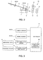
- FIG. 2 is a schematic sectional side view of a reversing controller of sheets showing an embodiment of this invention.
- a sheet 1 is a medium being conveyed such as a postal matter.
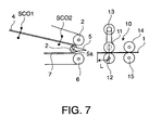
- the reversing controller is composed of a first conveying path 4, a length sensor SCO1, a timing sensor SCO2, a switching gate 5, a reversing portion 10, a conveying roller 6, and a second conveying path 7.
- the switching gate 5 has a flap shape to oscillate centering around a pivot 5a provided coaxially on the rotary shaft of the pinch roller 3 that will be described later.
- the first conveying path 4 conveys the sheet 1 in the first direction that is the arrow direction A.
- the length sensor SCO1 is arranged in the first conveying path 4 and detects a length of the sheet 1 arranged at the upper stream of the conveying path 4.
- the timing sensor SCO2 is used to set up a conveying control timing of the sheet 1 arranged at the downstream of the conveying path.
- the sensors SCO1 and SCO2 are composed of a light emitting element and a photo accepting element to receive a light from the light emitting element, respectively.
- the length sensor SCO1 detects the length of the sheet 1 being conveyed by measuring a time of light shielded by the sheet 1.
- the timing sensor SCO2 detects the front end of the sheet 1 at the moment when the light is shielded.
- the switching gate 5 sorts the conveyed sheets 1.
- the conveying roller 2 and the pinch roller 3 are provided in front of the switching gate 5.
- the reversing portion 10 takes in and reverses the sheets 1 sorted by the switching gate 5.
- the conveying roller 6 and the second conveying path 2 take in the sheets 1 sent from the reversing portion 10 and convey them in the second direction that is the reverse direction to the conveying direction of the first conveying path 4.
- the reversing portion 10 comprises a reversing roller 11 capable of rotating in the normal and reverse directions for taking and reversing the sheets 1 conveyed on the first conveying path 4, the pinch roller 12 arranged opposite to the reversing roller 11, conveying rollers 14 and 15 that are capable of rotating in the normal and reverse directions, and a reversing roller drive motor 13.
- the reversing roller 11 is connected to the reversing roller drive motor 13 and is driven normal or reverse directions by this reversing roller drive motor 13.
- the reversing roller drive motor 13 is connected to a controller 9 (see FIG. 3).
- FIG. 3 is a block diagram showing the construction of the control circuit of the reversing controller.
- the output signals from the length sensor SCO1 and the timing sensor SCO2 are input to the controller 9.
- the switching gate 5 is connected to a switching gate driver 8 and driven by this switching gate driver 8.
- the switching gate driver 8 is connected to the controller 9.
- the switching gate driver 8 rotates the switching gate 5 clockwise when the sheets 1 are conveyed to the reversing portion 10 through the first conveying path 4. Further, the switching gate driver 8 rotates the switching gate 5 counterclockwise when the sheets 1 are conveyed to the second conveying path 7 from the reversing portion 10.
- the controller 9 detects the lengths of the sheets 1 in the conveying direction from the output signal of the length sensor SCO1 and detects the front ends of the sheets 1 from the output signal of the timing sensor SCO2. Further, the controller 9 controls the switching gate driver 8 and rotates the switching gate 5 clockwise or counterclockwise to set the conveying direction of the sheet 1.
- controller 9 sets up a conveying control parameter 90 in order for setting the rotating velocity in the normal/reverse direction and the rotating velocity in the reverse direction of the reversing roller 11 and the pinch roller 12 of the reversing portion 10.
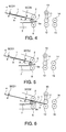
- FIG. 4 shows the state of the sheet 1 at the moment when the sheet 1 was conveyed on the first conveying path in the arrow direction A, its rear end passed the length sensor SC01 and the light from the light emitting element was changed from the shaded state to the acceptable state by the light receiving element.
- the controller 9 discriminates whether the sheet 1 has a length suited to the detecting medium and measures the length of the sheet 1 by counting a time of the light shaded in the length sensor SCO1 by the time unit clock.
- the controller 9 rotates the switching gate 5 clockwise and conveys the sheet 1.
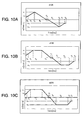
- FIG. 5 is a diagram showing the moment when the front end of the sheet 1 reaches the timing sensor SCO2. Further, timing diagrams showing the relation of subsequent conveying time and velocity are shown in FIG. 10A to FIG. 10C.
- the controller 9 sets the conveying control parameter 90 that is set according to the above-mentioned length of the sheet 1 in the reversing roller drive motor 13 and as a result, the reversing roller 11 is rotated in the normal direction.
- the rotating velocity ⁇ o of the reversing roller 11 is set for the conveying control parameter 90 so that the conveying velocity of the first conveying path 4 agrees with the tangential velocity that is a velocity in the tangential direction of the outer surface of the reversing roller 11 within a time T o until the front end of the sheet 1 reaches the nip between the reversing roller 11 and the pinch roller 12.
- FIG. 6 is a diagram showing the moment when the front end of the sheet 1 reaches the nip between the reversing roller 11 and the pinch roller 12.
- the rotating velocity is so set that the tangential velocity that is a velocity in the tangential direction of the outer surface of the reversing roller 11 reaches the conveying velocity of the first conveying path 4.
- the rotating velocity of the reversing roller 11 reached the velocity ⁇ o and therefore, the sheet 1 is smoothly taken in the reversing portion 10.
- a one-way roller is used for the conveying roller 2 and when, for example, the tangential velocity at the side of the reversing roller 11 and the pinch roller 12 is fast, the conveying roller 2 is able to run idle. Thus, it becomes possible to prevent the sheet 1 from being damaged.
- the controller 9 accelerates the rotating velocity of the reversing roller 11 by a specified time T 1 by controlling the reversing roller drive motor 13 based on the conveying control parameter 90 and then, rotates the reversing roller 11 at a rotating velocity ⁇ 1 that is faster than a rotating velocity ⁇ o for a specified time T 2 , then decelerates the velocity for a specified time T 3 and stops the reversing roller 11.
- FIG. 7 is a diagram showing the sheet 1 stopped in the state protruded from the reversing roller 11 and the pinch roller 12 by a length L.
- the sheet 1 is stopped for a certain fixed time T 4 .
- FIG. 8A to FIG. 8D are diagrams showing the length L of the sheet 1 protruding from the reversing roller 11 and the pinch roller 12 by the conveying control in the embodiment of this invention, respectively.
- the length L of the sheet 1 protruding from the reversing roller 11 and the pinch roller 12 as a result of the conveying control for changing the conveying control parameter 90 for every sheet 1 of optional length is shown.
- the length of the sheet 1 shown in FIG. 8A is used as a standard, the length of the sheet shown in FIG. 8B is longer than the length of the sheet 1 shown in FIG. 8B.
- the length of the sheet 1 shown in FIG. 8D is longer than the length of the sheet 1 shown in FIG. 8C.
- the conveyance of the sheet 1 is controlled based on the conveying control parameter 90 so that the length L protruding from the reversing roller 11 and the pinch roller 12 becomes constant.
- FIG. 9 shows the state of the sheet 1 that was driven in the reverse direction by the reversing roller 11 and the pinch roller 12 and sent to the second conveying path 7.
- the reversing roller 11 and the pinch roller 12 are accelerated in the reverse direction for a specified time T 5 so that the tangential velocity of the reversing roller 11 and the pinch roller 12 becomes the rotational velocity - ⁇ 2 faster than the conveying velocity from the stopped state of the sheet.
- the reversing roller 11 and the pinch roller 12 are rotated at the rotational velocity - ⁇ 2 for a specified time T 6 and decelerated for a specified time T 7 , and after reaching the rotational velocity - ⁇ o where the tangential velocity of the reversing roller 11 is turned to the reverse direction at the same size of the conveying velocity of the second conveying path, and this rotational velocity - ⁇ o is maintained for a time T 8 until the sheet 1 is completely separated from the reversing roller 11 and the pinch roller 12.
- a one-way roller is used for the conveying roller 6 and when the rotational velocity is fast at the reversing roller 11 and the pinch roller 12 side and the sheet 1 is fed at a high velocity, the conveying roller 6 is able to run idle.
- the sheet 1 is taken into the second conveying path 7.
- FIG. 10A to FIG. 10D are diagrams showing the velocity patterns relative to the control of the reversing roller drive motor 13 when the conveying control parameter 90 is set according to a size of the sheet 1.
- ⁇ o (rad/S) is a standard rotational velocity of the reversing roller 11.
- T 1 is a time of the rotational velocity of the reversing roller 11 is being accelerated to ⁇ 1 from ⁇ o .
- T 2 is a time of the reversing roller 11 rotating at a constant velocity of ⁇ 1 .
- T 3 is a time of the reversing roller 11 being decelerated from the rotational velocity ⁇ 1 to 0.
- T 4 is a time of the reversing roller 11 kept stopped.
- T 5 is a time of the rotational velocity of the reversing roller 11 being accelerated in the reverse direction from the rotational velocity 0 to - ⁇ 2 .
- T 6 is a time of the reversing roller 11 being rotated at a constant velocity of - ⁇ 2 .
- T 7 is a time of the rotational velocity of the reversing roller 11 being decelerated from - ⁇ 2 to ⁇ o .
- T 8 is a time of the reversing roller 11 rotating at a constant velocity - ⁇ o .
- the sheet 1 is sent to the second conveying path 7 at the rotational velocity - ⁇ o from the reversing roller 11 and the pinch roller 12.
- FIG. 10A is a velocity pattern diagram relative to the reversing roller drive control of the sheet d 135 that is a 135 mm long sheet 1.
- FIG. 10B is a velocity pattern diagram relative to the reversing roller drive control of the d195 sheet that is a 195 mm long sheet 1.
- FIG. 10C is a velocity pattern diagram relative to the reversing roller drive control of the d255 sheet that is a 255 mm long sheet 1.
- the d195 sheet is longer than the d135 sheet and therefore, the time T 2 rotating at the rotational velocity ⁇ 1 and the time T 6 rotating at the rotational velocity - ⁇ 2 become long.
- the d255 sheet is longer than the d195 sheet and the time T 2 rotating at the rotational velocity ⁇ 1 and the time T 6 rotating at the rotational velocity - ⁇ 2 become further long.
- the sheet 1 having a long length is conveyed at a high velocity while the reversing roller 11 is rotated at a higher rotational velocity ( ⁇ 1 at the normal rotation, - ⁇ 2 at the reversing) than the standard rotational velocity ( ⁇ o at the normal rotation, - ⁇ o at the reversing) for a longer time.
- the conveying gap between the sheets 1 becomes uniform and the high density conveyance becomes possible.
- the sheets 1 1 , 1 2 and 1 3 conveyed on the second conveying path 7 after reversed by the reversing portion 10 are conveyed without changing this conveying pitch.
- the longer sheets 1 can be taken into the reversing portion 10 from the first conveying path and fed out into the second conveying path 7 from the reversing portion 10 faster than the shorter sheets 1 and therefore, it becomes possible to convey plural sheets conveyed on the first conveying path 4 so that the conveying gap between plural sheets becomes equal to the conveying gap between plural sheets conveyed on the second conveying path after the reversing. That is, plural sheets 1 are conveyed without changing the conveying gap between plural sheets conveyed on the first conveying path 4 before reversing against the conveying gap between plural sheets conveyed on the second conveying path 7 after the reversing.
- the protruding amount of sheets can be set optionally by the arrangement of the switching gate 5 and the reversing portion 10 and therefore, it is possible to provide a sheet reversing controller capable of high density conveying.
- the protruding length of sheets when the sheets are stopped at the reversing portion can be controlled to a fixed length regardless sheet lengths and therefore, the conveying gaps between sheets become constant before and after the reversing and the high density conveying can be realized.
Landscapes
- Engineering & Computer Science (AREA)
- Mechanical Engineering (AREA)
- Separation, Sorting, Adjustment, Or Bending Of Sheets To Be Conveyed (AREA)
- Delivering By Means Of Belts And Rollers (AREA)
Priority Applications (1)
| Application Number | Priority Date | Filing Date | Title |
|---|---|---|---|
| EP10170096A EP2236446B1 (fr) | 2002-11-27 | 2003-08-28 | Dispositif pour retourner des courriers et procédé de retour |
Applications Claiming Priority (2)
| Application Number | Priority Date | Filing Date | Title |
|---|---|---|---|
| JP2002343248A JP4145638B2 (ja) | 2002-11-27 | 2002-11-27 | 紙葉類の反転制御装置及び紙葉類の反転制御方法 |
| JP2002343248 | 2002-11-27 |
Related Child Applications (1)
| Application Number | Title | Priority Date | Filing Date |
|---|---|---|---|
| EP10170096.1 Division-Into | 2010-07-20 |
Publications (3)
| Publication Number | Publication Date |
|---|---|
| EP1424299A2 true EP1424299A2 (fr) | 2004-06-02 |
| EP1424299A3 EP1424299A3 (fr) | 2005-01-26 |
| EP1424299B1 EP1424299B1 (fr) | 2010-09-29 |
Family
ID=32290436
Family Applications (2)
| Application Number | Title | Priority Date | Filing Date |
|---|---|---|---|
| EP10170096A Expired - Lifetime EP2236446B1 (fr) | 2002-11-27 | 2003-08-28 | Dispositif pour retourner des courriers et procédé de retour |
| EP03255334A Expired - Lifetime EP1424299B1 (fr) | 2002-11-27 | 2003-08-28 | Dispositif de commande pour retourner des feuilles et procédé de commande |
Family Applications Before (1)
| Application Number | Title | Priority Date | Filing Date |
|---|---|---|---|
| EP10170096A Expired - Lifetime EP2236446B1 (fr) | 2002-11-27 | 2003-08-28 | Dispositif pour retourner des courriers et procédé de retour |
Country Status (5)
| Country | Link |
|---|---|
| US (1) | US7080834B2 (fr) |
| EP (2) | EP2236446B1 (fr) |
| JP (1) | JP4145638B2 (fr) |
| KR (1) | KR100525536B1 (fr) |
| DE (2) | DE20321808U1 (fr) |
Cited By (7)
| Publication number | Priority date | Publication date | Assignee | Title |
|---|---|---|---|---|
| EP1514822A3 (fr) * | 2003-09-11 | 2005-04-20 | Kabushiki Kaisha Toshiba | Dispositif pour inverser la direction d'une feuille |
| KR100525536B1 (ko) * | 2002-11-27 | 2005-11-04 | 가부시끼가이샤 도시바 | 지엽류 반전제어장치 및 제어방법 |
| EP1754675A1 (fr) * | 2005-08-16 | 2007-02-21 | Kabushiki Kaisha Toshiba | Dispositif de manipulation de feuilles |
| EP1705144A3 (fr) * | 2005-03-22 | 2007-11-21 | Kabushiki Kaisha Toshiba | Dispositif et méthode pour traiter des feuilles en papier |
| EP1834910A3 (fr) * | 2006-03-17 | 2009-06-17 | Kabushiki Kaisha Toshiba | Mécanisme inverseur, appareil d'inversion et procédé d'inversion |
| EP2363363A2 (fr) | 2010-03-05 | 2011-09-07 | Siemens Aktiengesellschaft | Procédé et dispositif d'inversion de sens lors du transport d'objets |
| CN104425095A (zh) * | 2013-09-02 | 2015-03-18 | 曼罗兰网络系统有限责任公司 | 用于印刷再加工的装置 |
Families Citing this family (9)
| Publication number | Priority date | Publication date | Assignee | Title |
|---|---|---|---|---|
| JP4256251B2 (ja) * | 2003-12-17 | 2009-04-22 | 株式会社東芝 | 紙葉類方向反転装置、および紙葉類押印装置 |
| DE102004026362B3 (de) * | 2004-05-29 | 2005-11-03 | Siemens Ag | Vorrichtung zur Richtungsumkehr vor flachen Sendungen |
| US8628080B2 (en) * | 2005-12-23 | 2014-01-14 | Pitney Bowes Inc. | Method and system for controlling a staging transport in a mail processing machine |
| US7708276B2 (en) * | 2006-05-29 | 2010-05-04 | Ricoh Company, Ltd. | Sheet conveying path switching device used in image forming apparatus, and sheet conveying device |
| US20080212983A1 (en) * | 2007-02-06 | 2008-09-04 | Sang Gyu Park | Image forming apparatus and control method thereof |
| JP4998298B2 (ja) * | 2008-02-04 | 2012-08-15 | 沖電気工業株式会社 | 媒体処理装置 |
| US8280263B2 (en) | 2011-01-31 | 2012-10-02 | Xerox Corporation | Multi-feed detection and control system |
| KR101940296B1 (ko) * | 2012-10-09 | 2019-01-21 | 에이치피프린팅코리아 유한회사 | 급지장치 및 이를 포함하는 화상형성장치 |
| JP7718169B2 (ja) * | 2021-08-25 | 2025-08-05 | 富士フイルムビジネスイノベーション株式会社 | 画像形成装置 |
Citations (2)
| Publication number | Priority date | Publication date | Assignee | Title |
|---|---|---|---|---|
| DE4315053A1 (de) | 1993-05-06 | 1994-11-10 | Licentia Gmbh | Vorrichtung zur Richtungsumkehr von flachen Sendungen |
| EP1295826A2 (fr) | 2001-09-21 | 2003-03-26 | Kabushiki Kaisha Toshiba | Méthode et dispositif de retour |
Family Cites Families (23)
| Publication number | Priority date | Publication date | Assignee | Title |
|---|---|---|---|---|
| US4331328A (en) * | 1980-06-30 | 1982-05-25 | Burroughs Corporation | Controller for a servo driven document feeder |
| JPS57165642U (fr) * | 1981-04-14 | 1982-10-19 | ||
| JPS5922847A (ja) * | 1982-07-29 | 1984-02-06 | Fuji Xerox Co Ltd | シ−ト反転装置 |
| US4487506A (en) * | 1982-08-23 | 1984-12-11 | Xerox Corporation | Reversing roll inverter with bypass capability |
| JPS61110664U (fr) * | 1984-12-22 | 1986-07-12 | ||
| JP3010091B2 (ja) | 1991-10-11 | 2000-02-14 | 三田工業株式会社 | シート反転装置 |
| US5449166A (en) * | 1993-05-06 | 1995-09-12 | Licentia Patent-Verwaltungs-Gmbh | Apparatus for reversing the direction of flat items |
| US5887868A (en) * | 1993-12-09 | 1999-03-30 | Xerox Corporation | Drive system for rollers |
| US5449164A (en) * | 1994-08-29 | 1995-09-12 | Xerox Corporation | Sheet inverter apparatus |
| DE4431800A1 (de) | 1994-09-07 | 1996-03-14 | Licentia Gmbh | Vorrichtung zur Umkehrung der Transportrichtung von flachen Sendungen |
| US5461468A (en) * | 1994-10-31 | 1995-10-24 | Xerox Corporation | Document handler interdocument gap control system |
| DE19522131C2 (de) | 1995-06-19 | 1999-01-07 | Kodak Ag | Transportvorrichtung für Blätter |
| BE1010140A3 (nl) | 1995-10-06 | 1998-01-06 | Alcatel Bell Nv | Omkeermodule voor poststukken. |
| JP3401549B2 (ja) * | 1996-06-06 | 2003-04-28 | 沖電気工業株式会社 | 紙葉搬送装置 |
| US5689795A (en) * | 1996-09-24 | 1997-11-18 | Xerox Corporation | Sheet transfer apparatus with adaptive speed-up delay |
| US6132352A (en) * | 1998-11-23 | 2000-10-17 | Xerox Corporation | Dual mode inverter and automatic variable fold position sheet folding system |
| US6322069B1 (en) * | 1999-03-12 | 2001-11-27 | Xerox Corporation | Interpaper spacing control in a media handling system |
| DE19936369C1 (de) * | 1999-08-03 | 2000-10-19 | Siemens Ag | Verfahren und Vorrichtung zur Korrektur der Lücken zwischen Sendungen |
| US6662929B1 (en) * | 2000-11-17 | 2003-12-16 | Lockhead Martin Corporation | Parcel singulation software control logic |
| US6550762B2 (en) * | 2000-12-05 | 2003-04-22 | Xerox Corporation | High speed printer with dual alternate sheet inverters |
| JP2002343248A (ja) | 2001-05-10 | 2002-11-29 | Toshiba Corp | 蛍光面の形成方法および画像表示装置 |
| JP4145638B2 (ja) * | 2002-11-27 | 2008-09-03 | 株式会社東芝 | 紙葉類の反転制御装置及び紙葉類の反転制御方法 |
| JP4526788B2 (ja) | 2003-07-04 | 2010-08-18 | 花王株式会社 | 水系インク |
-
2002
- 2002-11-27 JP JP2002343248A patent/JP4145638B2/ja not_active Expired - Lifetime
-
2003
- 2003-08-19 KR KR10-2003-0057137A patent/KR100525536B1/ko not_active Expired - Fee Related
- 2003-08-26 US US10/647,467 patent/US7080834B2/en not_active Expired - Lifetime
- 2003-08-28 DE DE20321808U patent/DE20321808U1/de not_active Expired - Lifetime
- 2003-08-28 EP EP10170096A patent/EP2236446B1/fr not_active Expired - Lifetime
- 2003-08-28 DE DE60334358T patent/DE60334358D1/de not_active Expired - Lifetime
- 2003-08-28 EP EP03255334A patent/EP1424299B1/fr not_active Expired - Lifetime
Patent Citations (2)
| Publication number | Priority date | Publication date | Assignee | Title |
|---|---|---|---|---|
| DE4315053A1 (de) | 1993-05-06 | 1994-11-10 | Licentia Gmbh | Vorrichtung zur Richtungsumkehr von flachen Sendungen |
| EP1295826A2 (fr) | 2001-09-21 | 2003-03-26 | Kabushiki Kaisha Toshiba | Méthode et dispositif de retour |
Cited By (13)
| Publication number | Priority date | Publication date | Assignee | Title |
|---|---|---|---|---|
| KR100525536B1 (ko) * | 2002-11-27 | 2005-11-04 | 가부시끼가이샤 도시바 | 지엽류 반전제어장치 및 제어방법 |
| EP1514822A3 (fr) * | 2003-09-11 | 2005-04-20 | Kabushiki Kaisha Toshiba | Dispositif pour inverser la direction d'une feuille |
| EP1705144A3 (fr) * | 2005-03-22 | 2007-11-21 | Kabushiki Kaisha Toshiba | Dispositif et méthode pour traiter des feuilles en papier |
| US7597320B2 (en) | 2005-03-22 | 2009-10-06 | Kabushiki Kaisha Toshiba | Apparatus for processing paper sheets and method of processing paper sheets |
| EP1754675A1 (fr) * | 2005-08-16 | 2007-02-21 | Kabushiki Kaisha Toshiba | Dispositif de manipulation de feuilles |
| US8286963B2 (en) | 2005-08-16 | 2012-10-16 | Kabushiki Kaisha Toshiba | Sheet handling apparatus |
| US7946577B2 (en) | 2006-03-17 | 2011-05-24 | Kabushiki Kaisha Toshiba | Switchback mechanism, switchback apparatus, and switchback method |
| EP1834910A3 (fr) * | 2006-03-17 | 2009-06-17 | Kabushiki Kaisha Toshiba | Mécanisme inverseur, appareil d'inversion et procédé d'inversion |
| EP2363363A2 (fr) | 2010-03-05 | 2011-09-07 | Siemens Aktiengesellschaft | Procédé et dispositif d'inversion de sens lors du transport d'objets |
| DE102010010375A1 (de) | 2010-03-05 | 2011-09-08 | Siemens Aktiengesellschaft | Verfahren und Vorrichtung zur Richtungsumkehr beim Transport von Gegenständen |
| US8276743B2 (en) | 2010-03-05 | 2012-10-02 | Siemens Aktiengesellschaft | Method and apparatus for the reversal of direction in the transport of articles |
| CN104425095A (zh) * | 2013-09-02 | 2015-03-18 | 曼罗兰网络系统有限责任公司 | 用于印刷再加工的装置 |
| CN104425095B (zh) * | 2013-09-02 | 2017-05-10 | 曼罗兰网络系统有限责任公司 | 用于印刷再加工的装置 |
Also Published As
| Publication number | Publication date |
|---|---|
| DE60334358D1 (de) | 2010-11-11 |
| JP4145638B2 (ja) | 2008-09-03 |
| EP1424299A3 (fr) | 2005-01-26 |
| DE20321808U1 (de) | 2010-06-17 |
| JP2004175507A (ja) | 2004-06-24 |
| KR20040047547A (ko) | 2004-06-05 |
| US7080834B2 (en) | 2006-07-25 |
| EP1424299B1 (fr) | 2010-09-29 |
| US20040100017A1 (en) | 2004-05-27 |
| KR100525536B1 (ko) | 2005-11-04 |
| EP2236446A1 (fr) | 2010-10-06 |
| EP2236446B1 (fr) | 2011-11-16 |
Similar Documents
| Publication | Publication Date | Title |
|---|---|---|
| US7080834B2 (en) | Sheets reversing controller and control method | |
| US7258340B2 (en) | Sheet registration within a media inverter | |
| US7416185B2 (en) | Inverter with return/bypass paper path | |
| US6402133B1 (en) | Sheet conveying apparatus and image forming apparatus having the same | |
| US6896257B2 (en) | Sheet feeding apparatus | |
| US7547016B2 (en) | Motor control apparatus with controlled input current | |
| JP2928298B2 (ja) | 自動原稿送り装置 | |
| US6883800B2 (en) | Paper convey method and device in image forming apparatus | |
| JPH1159965A (ja) | 紙搬送装置 | |
| US6478298B1 (en) | Fixed station sorter/mailbox with passive gate station entrance system | |
| JP2003146484A (ja) | 用紙搬送装置 | |
| JP2925614B2 (ja) | 自動原稿送り装置 | |
| JP2003264671A (ja) | 画像読取装置 | |
| JP2852943B2 (ja) | 複写装置 | |
| JP2559185Y2 (ja) | 自動原稿送り装置 | |
| JP2747169B2 (ja) | 紙葉類の搬送路切り換え装置 | |
| JP2867023B2 (ja) | シート搬送装置 | |
| KR940002126B1 (ko) | 자동 원고급지 장치의 제어장치 및 방법 | |
| JP2992090B2 (ja) | 原稿搬送装置を備えた電子写真装置 | |
| JPH0750364Y2 (ja) | 自動原稿送り装置 | |
| JPH10181948A (ja) | シート材搬送装置および画像読取装置および画像形成装置 | |
| JPH10218426A (ja) | 自動シート材送り装置、及び該自動シート材送り装置を備えた画像形成装置 | |
| JP3378650B2 (ja) | 自動原稿送り装置 | |
| JP2005335940A (ja) | シート状部材搬送装置 | |
| JP3832916B2 (ja) | 自動原稿給紙装置及びこれを備えた画像形成装置 |
Legal Events
| Date | Code | Title | Description |
|---|---|---|---|
| PUAI | Public reference made under article 153(3) epc to a published international application that has entered the european phase |
Free format text: ORIGINAL CODE: 0009012 |
|
| 17P | Request for examination filed |
Effective date: 20030924 |
|
| AK | Designated contracting states |
Kind code of ref document: A2 Designated state(s): AT BE BG CH CY CZ DE DK EE ES FI FR GB GR HU IE IT LI LU MC NL PT RO SE SI SK TR |
|
| AX | Request for extension of the european patent |
Extension state: AL LT LV MK |
|
| PUAL | Search report despatched |
Free format text: ORIGINAL CODE: 0009013 |
|
| AK | Designated contracting states |
Kind code of ref document: A3 Designated state(s): AT BE BG CH CY CZ DE DK EE ES FI FR GB GR HU IE IT LI LU MC NL PT RO SE SI SK TR |
|
| AX | Request for extension of the european patent |
Extension state: AL LT LV MK |
|
| AKX | Designation fees paid |
Designated state(s): DE FR GB SE |
|
| 17Q | First examination report despatched |
Effective date: 20060102 |
|
| GRAP | Despatch of communication of intention to grant a patent |
Free format text: ORIGINAL CODE: EPIDOSNIGR1 |
|
| RTI1 | Title (correction) |
Free format text: SHEETS REVERSING CONTROLLER AND CONTROL METHOD |
|
| GRAS | Grant fee paid |
Free format text: ORIGINAL CODE: EPIDOSNIGR3 |
|
| GRAA | (expected) grant |
Free format text: ORIGINAL CODE: 0009210 |
|
| AK | Designated contracting states |
Kind code of ref document: B1 Designated state(s): DE FR GB SE |
|
| REG | Reference to a national code |
Ref country code: GB Ref legal event code: FG4D |
|
| REF | Corresponds to: |
Ref document number: 60334358 Country of ref document: DE Date of ref document: 20101111 Kind code of ref document: P |
|
| PG25 | Lapsed in a contracting state [announced via postgrant information from national office to epo] |
Ref country code: SE Free format text: LAPSE BECAUSE OF FAILURE TO SUBMIT A TRANSLATION OF THE DESCRIPTION OR TO PAY THE FEE WITHIN THE PRESCRIBED TIME-LIMIT Effective date: 20100929 |
|
| PLBE | No opposition filed within time limit |
Free format text: ORIGINAL CODE: 0009261 |
|
| STAA | Information on the status of an ep patent application or granted ep patent |
Free format text: STATUS: NO OPPOSITION FILED WITHIN TIME LIMIT |
|
| 26N | No opposition filed |
Effective date: 20110630 |
|
| REG | Reference to a national code |
Ref country code: DE Ref legal event code: R097 Ref document number: 60334358 Country of ref document: DE Effective date: 20110630 |
|
| REG | Reference to a national code |
Ref country code: DE Ref legal event code: R082 Ref document number: 60334358 Country of ref document: DE Representative=s name: HORN KLEIMANN WAITZHOFER, PATENTANWAELTE, DE Ref country code: DE Ref legal event code: R082 Ref document number: 60334358 Country of ref document: DE Representative=s name: HORN KLEIMANN WAITZHOFER PATENTANWAELTE, DE Ref country code: DE Ref legal event code: R082 Ref document number: 60334358 Country of ref document: DE Representative=s name: HORN KLEIMANN WAITZHOFER PATENTANWAELTE PARTG , DE |
|
| GBPC | Gb: european patent ceased through non-payment of renewal fee |
Effective date: 20110828 |
|
| PG25 | Lapsed in a contracting state [announced via postgrant information from national office to epo] |
Ref country code: GB Free format text: LAPSE BECAUSE OF NON-PAYMENT OF DUE FEES Effective date: 20110828 |
|
| REG | Reference to a national code |
Ref country code: FR Ref legal event code: PLFP Year of fee payment: 14 |
|
| REG | Reference to a national code |
Ref country code: FR Ref legal event code: PLFP Year of fee payment: 15 |
|
| REG | Reference to a national code |
Ref country code: FR Ref legal event code: PLFP Year of fee payment: 16 |
|
| PGFP | Annual fee paid to national office [announced via postgrant information from national office to epo] |
Ref country code: FR Payment date: 20210714 Year of fee payment: 19 |
|
| PGFP | Annual fee paid to national office [announced via postgrant information from national office to epo] |
Ref country code: DE Payment date: 20220608 Year of fee payment: 20 |
|
| PG25 | Lapsed in a contracting state [announced via postgrant information from national office to epo] |
Ref country code: FR Free format text: LAPSE BECAUSE OF NON-PAYMENT OF DUE FEES Effective date: 20220831 |
|
| REG | Reference to a national code |
Ref country code: DE Ref legal event code: R071 Ref document number: 60334358 Country of ref document: DE |