EP1424444A2 - Vorrichtung zur Montage von Schienenklemmen - Google Patents
Vorrichtung zur Montage von Schienenklemmen Download PDFInfo
- Publication number
- EP1424444A2 EP1424444A2 EP03450244A EP03450244A EP1424444A2 EP 1424444 A2 EP1424444 A2 EP 1424444A2 EP 03450244 A EP03450244 A EP 03450244A EP 03450244 A EP03450244 A EP 03450244A EP 1424444 A2 EP1424444 A2 EP 1424444A2
- Authority
- EP
- European Patent Office
- Prior art keywords
- rail
- tool
- tool carrier
- track
- axis
- Prior art date
- Legal status (The legal status is an assumption and is not a legal conclusion. Google has not performed a legal analysis and makes no representation as to the accuracy of the status listed.)
- Granted
Links
- 241001669679 Eleotris Species 0.000 claims 1
- 230000009977 dual effect Effects 0.000 abstract 1
- 238000010276 construction Methods 0.000 description 4
- 108010066278 cabin-4 Proteins 0.000 description 2
- 238000006073 displacement reaction Methods 0.000 description 1
- 238000000034 method Methods 0.000 description 1
- 210000000056 organ Anatomy 0.000 description 1
- 230000001360 synchronised effect Effects 0.000 description 1
Images

Classifications
-
- E—FIXED CONSTRUCTIONS
- E01—CONSTRUCTION OF ROADS, RAILWAYS, OR BRIDGES
- E01B—PERMANENT WAY; PERMANENT-WAY TOOLS; MACHINES FOR MAKING RAILWAYS OF ALL KINDS
- E01B29/00—Laying, rebuilding, or taking-up tracks; Tools or machines therefor
- E01B29/24—Fixing or removing detachable fastening means or accessories thereof; Pre-assembling track components by detachable fastening means
Definitions
- the invention relates to a device for mounting a rail a rail clamp connecting a threshold of a track, consisting from two opposite and by an additional cylinder in Machine or track transverse direction movable about a pivot axis Tool levers, at the lower end of each one to rest against one Rail clamp provided pressure element is provided.
- the height adjustable arranged on a track-moveable machine frame is and has tool lever that with its upper end on the Swivel axis are stored.
- the auxiliary cylinder is approximately in the longitudinal center the two levers articulated to this.
- a pressure element for inserting a rail clamp provided towards the rail.
- another pressure element arranged, which consists of two - one Rotatable axis normal to the longitudinal direction of the rail - press-on lugs consists.
- Another device for dismantling rail clamps is in the WO 99/24669.
- One arranged on the tool lever A stop is assigned to the pressure element for pressing out the rail clamp, rotatable about an axis running in the longitudinal direction of the rail or can be lowered into the operating position and the sliding movement the rail clamp limited.
- WO 00/36219 discloses a device in which the pressing members each rebuilt according to application for pushing in or pushing out rail clamps or be replaced.
- the organ for pushing out the The clamp is on its holder by one in the longitudinal direction of the rail running axis rotatably mounted.
- the side movement of the two Tool lever is based on a strut articulated on both levers synchronized.
- the object of the present invention is to create a Device of the generic type with simple design means a quick changeover between the two types of use for or expansion of rail clamps.
- this object is achieved with a device of the beginning mentioned type in that two on each tool lever Cross track direction spaced apart and on a common Tool carrier mounted pressure elements are arranged, the Tool carrier rotatable about a tool carrier axis on the tool lever is stored.
- This training will make it particularly efficient and easy usable device created in the - with appropriate arrangement or alignment of the pressure elements on the tool carrier - only a rotation of the same around the tool carrier axis is required is to switch between the two possible uses. It is it is particularly advantageous that when pivoting a pressure element in the Use position simultaneously and automatically the other, on the same Tool carrier arranged pressure element in the non-operating position is turned up and therefore no hindrance to the side movement of the tool lever can represent.
- the structurally simple arrangement allows the device to be designed to be particularly robust, thereby relatively high contact pressures that occur during use to be able to withstand.
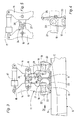
- a track construction vehicle 1 visible in FIG. 1 and partly also in FIG. 2 has a machine frame 2, which with a drive motor 3 and an operator cabin 4 and equipped with rail trolleys 5 can be moved on a track 6 in a working direction 7.
- Track 6 is composed of rails 8, sleepers 9 and the rails and sleepers interconnecting rail clamps 10 together.
- each rail Track 6 each arranged a device 11, the for mounting or dismounting the rail clamps 10 is provided and will be described in more detail below.
- the two devices 11 are on the machine frame 2 around a running in the transverse direction Axis 12 is pivotally mounted and connected to a tilt drive 13. In this way, each device 11 can be rotated approximately 90 ° from one (in dash-dotted lines indicated) inoperative position in a Be pivoted away in the device 11 in each case exactly below or to the side of an operator located in the cabin 4 is positioned.
- the device 11 has approximately two vertically extending tool lever 14 on each other in the transverse direction of the track with respect to the associated rail 8 opposite.
- the two Tool levers 14 are each about a - aligned in the longitudinal direction of the track - Swivel axis 15 is movable and based on its upper ends 16 an auxiliary cylinder 17 connected to each other.
- At the bottom is 18 each tool lever 14 with two on a common tool carrier 19 mounted pressure elements 20 and 21 equipped in the cross-track direction spaced from each other and for optional investment in a Rail clamp 10 are provided.
- the tool carrier 19 is there mounted on the tool lever 14 so as to be rotatable about a tool carrier axis 22, which is normal to the direction of the rail or track.
- a swivel drive 25 in 4 schematically indicated
- the two are on the same tool carrier 19 attached pressure members 20,21 with respect to the tool carrier axis 22 offset or rotated against each other, wherein the angle of this twist can be approximately 90 ° to approximately 120 °.
- the pressure elements 20 and 21 of the two tool levers 14 are in their working position coordinated so that the same on both longitudinal sides of the rail 8 Work process (i.e. assembly or disassembly) takes place.
- a synchronization device 24 is provided, on the basis of which the tool levers 14 positively coupled in opposite directions in their movement are.
- the synchronization device 24 can, for example, as shown in FIG. 5 shown in detail, in the form of a tool lever 14 rotatably arranged sliding block 26 to be executed in a with the other tool lever 14 connected fork 27 slidably mounted is. Alternatively, it would also be possible to switch off the synchronization device 24 a.
- the device 11 is operated by means of the tilt drive 13 pivoted into the operating position. Then the positioning takes place the pressure elements 20 and 21 by manual or remote-controlled Rotation of the tool carrier 19 about the tool carrier axis 22 to do that for each application (either postponing the already on the threshold 9 provided rail clamps 10 on the rail foot 23 or removal of the rail clamp 10 from the rail 8) needed Bring the pressure element into the vertical working position. To the side Centering of the device 11 on the rail 8 and for height adjustment corresponding adjustable guide elements 28 are provided (Fig. 3).
- the device 11 can be in an in-use position sliding guide 29 extending in the longitudinal direction of the track be a band cylinder 30 for longitudinal adjustment of the device 11 in with respect to the machine frame 2.
- the respective device 11 is preceded by a sensor 31, which is mounted on the machine frame 2 in a height-adjustable manner by means of a drive 32 and can be unrolled in use on the rail 8.
- the sensor 31 registers the position of the rail clamps 10 and gives a corresponding signal to a control device 33, which in turn staggered the correct positioning of the device 11 triggers over the rail clamp 10 concerned and based on of the auxiliary cylinder 17, the pressing members 20 or 21 in the transverse direction of the track moved to selectively mount the rail clamps 10 or remove.
- the threshold 9 by means of a (only shown in Fig. 1) Threshold lifting device 34 raised and against from below the rail 8 are pressed while using the rail clamp 10 of the pressing member 20 is pushed onto the rail foot 23.
Landscapes
- Engineering & Computer Science (AREA)
- Architecture (AREA)
- Civil Engineering (AREA)
- Structural Engineering (AREA)
- Machines For Laying And Maintaining Railways (AREA)
- Lift-Guide Devices, And Elevator Ropes And Cables (AREA)
- Input Circuits Of Receivers And Coupling Of Receivers And Audio Equipment (AREA)
- Shaping By String And By Release Of Stress In Plastics And The Like (AREA)
- Automobile Manufacture Line, Endless Track Vehicle, Trailer (AREA)
Abstract
Description
Claims (5)
- Vorrichtung zur Montage von eine Schiene (8) mit einer Schwelle (9) eines Gleises (6) verbindenden Schienenklemmen (10), bestehend aus zwei einander gegenüberliegenden und durch einen Beistellzylinder (17) in Maschinen- bzw. Gleisquerrichtung um eine Schwenkachse (15) bewegbaren Werkzeughebeln (14), an deren unterem Ende (18) jeweils ein zur Anlage an eine Schienenklemme (10) vorgesehenes Anpreßorgan (20,21) vorgesehen ist, dadurch gekennzeichnet, daß an jedem Werkzeughebel (14) zwei in Gleisquerrichtung voneinander distanzierte und auf einem gemeinsamen Werkzeugträger (19) montierte Anpreßorgane (20,21) angeordnet sind, wobei der Werkzeugträger (19) um eine Werkzeugträgerachse (22) verdrehbar am Werkzeughebel (14) gelagert ist.
- Vorrichtung nach Anspruch 1, dadurch gekennzeichnet, daß die Werkzeugträgerachse (22) normal zur Maschinen- bzw. Schienenlängsrichtung verläuft.
- Vorrichtung nach Anspruch 1 oder 2, dadurch gekennzeichnet, daß der Werkzeugträger (19) mit einem Schwenkantrieb (25) für eine Verdrehung um die Werkzeugträgerachse (22) verbunden ist.
- Vorrichtung nach einem der Ansprüche 1 bis 3, dadurch gekennzeichnet, daß die beiden auf demselben Werkzeugträger (19) vorgesehenen Anpreßorgane (20,21) bezüglich der Werkzeugträgerachse (22) um einen Winkel von etwa 90° bis etwa 120° gegeneinander verdreht angeordnet sind.
- Vorrichtung nach einem der Ansprüche 1 bis 3, dadurch gekennzeichnet, daß die Beistellbewegung der beiden Werkzeughebel (14) anhand einer Synchronisiereinrichtung (24) gegenläufig zwangsgekoppelt ist.
Applications Claiming Priority (2)
| Application Number | Priority Date | Filing Date | Title |
|---|---|---|---|
| DE20218377U | 2002-11-27 | ||
| DE20218377U DE20218377U1 (de) | 2002-11-27 | 2002-11-27 | Vorrichtung zur Montage von Schienenklemmen |
Publications (3)
| Publication Number | Publication Date |
|---|---|
| EP1424444A2 true EP1424444A2 (de) | 2004-06-02 |
| EP1424444A3 EP1424444A3 (de) | 2005-05-04 |
| EP1424444B1 EP1424444B1 (de) | 2009-04-29 |
Family
ID=7977393
Family Applications (1)
| Application Number | Title | Priority Date | Filing Date |
|---|---|---|---|
| EP03450244A Expired - Lifetime EP1424444B1 (de) | 2002-11-27 | 2003-11-03 | Vorrichtung zur Montage von Schienenklemmen |
Country Status (6)
| Country | Link |
|---|---|
| EP (1) | EP1424444B1 (de) |
| CN (1) | CN1215228C (de) |
| AT (1) | ATE430220T1 (de) |
| DE (2) | DE20218377U1 (de) |
| DK (1) | DK1424444T3 (de) |
| ES (1) | ES2325152T3 (de) |
Cited By (7)
| Publication number | Priority date | Publication date | Assignee | Title |
|---|---|---|---|---|
| WO2006021879A1 (de) * | 2004-08-27 | 2006-03-02 | Matisa Materiel Industriel S.A. | Vorrichtung zur demontage von schienenklemmen |
| GB2421535A (en) * | 2004-12-22 | 2006-06-28 | Robel Bahnbaumaschinen Gmbh | A lifting clamp for lifting sleepers |
| WO2012067575A1 (en) | 2010-11-19 | 2012-05-24 | Rosenqvist Rail Ab | Manually operated arrangement |
| US8371225B2 (en) | 2005-07-20 | 2013-02-12 | Multiclip Co. Ltd. | Device, method, and apparatus for lifting a railway rail |
| WO2018050917A1 (de) * | 2016-09-19 | 2018-03-22 | Schwihag Ag | Greifmechanismus für spindel-schraub-clip-maschine |
| WO2022002559A1 (de) * | 2020-06-30 | 2022-01-06 | Schwihag Ag | Schienengebundene montagevorrichtung für spannklemmen zum befestigen einer schiene auf einer schienenschwelle und verfahren |
| CN114263074A (zh) * | 2022-01-24 | 2022-04-01 | 洛阳双瑞橡塑科技有限公司 | 一种基于浮轨扣件快速安装用的便携式工具及方法 |
Families Citing this family (1)
| Publication number | Priority date | Publication date | Assignee | Title |
|---|---|---|---|---|
| CN108560335A (zh) * | 2018-06-04 | 2018-09-21 | 华东交通大学 | 轨道齿轮式可伸缩调节防爬撑 |
Citations (4)
| Publication number | Priority date | Publication date | Assignee | Title |
|---|---|---|---|---|
| WO1997004175A1 (en) | 1995-07-18 | 1997-02-06 | Everts & Van Der Weijden Exploitatie Maatschappij Ewem B.V. | A tool for removing a railway fastening clip from a rail |
| US5839377A (en) | 1997-02-14 | 1998-11-24 | Racine Railroad Products, Inc. | Apparatus and method for applying and removing transversely applied elastic rail clips |
| WO1999024669A1 (en) | 1997-11-06 | 1999-05-20 | A. Rosenquist Förvaltnings Ab | An arrangement for bringing a clamping element from a fastening position to a released position |
| WO2000036219A1 (en) | 1998-12-03 | 2000-06-22 | A. Rosenquist Förvaltnings Ab | Device for moving two railway fastening means |
Family Cites Families (1)
| Publication number | Priority date | Publication date | Assignee | Title |
|---|---|---|---|---|
| DE20304727U1 (de) * | 2003-03-25 | 2003-05-28 | ROBEL Bahnbaumaschinen GmbH, 83395 Freilassing | Vorrichtung zur Montage von Schienenklemmen |
-
2002
- 2002-11-27 DE DE20218377U patent/DE20218377U1/de not_active Expired - Lifetime
-
2003
- 2003-11-03 DK DK03450244T patent/DK1424444T3/da active
- 2003-11-03 EP EP03450244A patent/EP1424444B1/de not_active Expired - Lifetime
- 2003-11-03 ES ES03450244T patent/ES2325152T3/es not_active Expired - Lifetime
- 2003-11-03 DE DE50311471T patent/DE50311471D1/de not_active Expired - Lifetime
- 2003-11-03 AT AT03450244T patent/ATE430220T1/de active
- 2003-11-24 CN CN200310118089.3A patent/CN1215228C/zh not_active Expired - Fee Related
Patent Citations (4)
| Publication number | Priority date | Publication date | Assignee | Title |
|---|---|---|---|---|
| WO1997004175A1 (en) | 1995-07-18 | 1997-02-06 | Everts & Van Der Weijden Exploitatie Maatschappij Ewem B.V. | A tool for removing a railway fastening clip from a rail |
| US5839377A (en) | 1997-02-14 | 1998-11-24 | Racine Railroad Products, Inc. | Apparatus and method for applying and removing transversely applied elastic rail clips |
| WO1999024669A1 (en) | 1997-11-06 | 1999-05-20 | A. Rosenquist Förvaltnings Ab | An arrangement for bringing a clamping element from a fastening position to a released position |
| WO2000036219A1 (en) | 1998-12-03 | 2000-06-22 | A. Rosenquist Förvaltnings Ab | Device for moving two railway fastening means |
Cited By (13)
| Publication number | Priority date | Publication date | Assignee | Title |
|---|---|---|---|---|
| WO2006021879A1 (de) * | 2004-08-27 | 2006-03-02 | Matisa Materiel Industriel S.A. | Vorrichtung zur demontage von schienenklemmen |
| US7677177B2 (en) | 2004-08-27 | 2010-03-16 | MATISA Matériel Industriel SA | Device for the disassembly of rail anchors |
| CN101023219B (zh) * | 2004-08-27 | 2011-02-23 | 马蒂萨材料工业股份有限公司 | 拆除防爬器用的装置 |
| GB2421535A (en) * | 2004-12-22 | 2006-06-28 | Robel Bahnbaumaschinen Gmbh | A lifting clamp for lifting sleepers |
| GB2421535B (en) * | 2004-12-22 | 2007-12-27 | Robel Bahnbaumaschinen Gmbh | A lifting clamp for lifting sleepers |
| US8371225B2 (en) | 2005-07-20 | 2013-02-12 | Multiclip Co. Ltd. | Device, method, and apparatus for lifting a railway rail |
| WO2012067575A1 (en) | 2010-11-19 | 2012-05-24 | Rosenqvist Rail Ab | Manually operated arrangement |
| EP2640896A4 (de) * | 2010-11-19 | 2016-10-05 | Rosenqvist Rail Ab | Handbetätigte anordnung |
| WO2018050917A1 (de) * | 2016-09-19 | 2018-03-22 | Schwihag Ag | Greifmechanismus für spindel-schraub-clip-maschine |
| US11293145B2 (en) | 2016-09-19 | 2022-04-05 | Schwihag Ag | Gripping mechanism for spindle-screw clipping machine |
| WO2022002559A1 (de) * | 2020-06-30 | 2022-01-06 | Schwihag Ag | Schienengebundene montagevorrichtung für spannklemmen zum befestigen einer schiene auf einer schienenschwelle und verfahren |
| CN114263074A (zh) * | 2022-01-24 | 2022-04-01 | 洛阳双瑞橡塑科技有限公司 | 一种基于浮轨扣件快速安装用的便携式工具及方法 |
| CN114263074B (zh) * | 2022-01-24 | 2025-01-28 | 洛阳双瑞橡塑科技有限公司 | 一种基于浮轨扣件快速安装用的便携式工具及方法 |
Also Published As
| Publication number | Publication date |
|---|---|
| ATE430220T1 (de) | 2009-05-15 |
| DE20218377U1 (de) | 2003-02-13 |
| DE50311471D1 (de) | 2009-06-10 |
| ES2325152T3 (es) | 2009-08-27 |
| DK1424444T3 (da) | 2009-08-03 |
| CN1215228C (zh) | 2005-08-17 |
| EP1424444B1 (de) | 2009-04-29 |
| CN1502746A (zh) | 2004-06-09 |
| EP1424444A3 (de) | 2005-05-04 |
Similar Documents
| Publication | Publication Date | Title |
|---|---|---|
| AT402830B (de) | Schienenziehvorrichtung zum längsverschieben von schienen verlegter gleise | |
| DD152594A5 (de) | Maschine zur bearbeitung der schienenkopfoberflaeche eines verlegten gleises | |
| AT508755B1 (de) | Stopfmaschine mit einer zusatzhebeeinrichtung | |
| AT506585B1 (de) | Stopfmaschine | |
| EP1424444B1 (de) | Vorrichtung zur Montage von Schienenklemmen | |
| DE752961C (de) | Verriegelungseinrichtung fuer Koksofentueren | |
| AT403812B (de) | Maschine zum anpressen von schwellenankern | |
| DE2602162C2 (de) | Bezugssystemanordnung für Gleisbaumaschinen | |
| EP0734895A1 (de) | Fahrzeugdach | |
| EP1611287B1 (de) | Vorrichtung zur montage von schienenklemmen | |
| DE2234670C3 (de) | Vorrichtung zum Abbiegen der Enden von Offsetdruckplatten | |
| DE2245719C3 (de) | Vignolschienenweiche | |
| EP0511950B1 (de) | Vorrichtung zum Eingleisen eines Werkzeugrahmens | |
| EP0287800A1 (de) | Extrusionskopf mit einer Klemmeinrichtung für die Werkzeugteile | |
| DE19602568C2 (de) | Vorrichtung zum Druckan-/ und -abstellen eines Zylinders | |
| EP1185846B1 (de) | Auswuchtvorrichtung | |
| DE2126347B2 (de) | Vorrichtung zum Reinigen der Räder von Fahrzeugen | |
| EP1842674B1 (de) | Montagesystem mit einem Führungselement zum Führen einer Reinigungsvorrichtung einer Druckmaschine | |
| EP2233639A2 (de) | Vorrichtung zum Einbau von Schienenklemmen | |
| DE2349152A1 (de) | Stromabnehmer fuer die dritte schiene | |
| DE19915488B4 (de) | Vorrichtung zum Biegen eines Metallbandes | |
| DE1652565C3 (de) | Vorrichtung zum Führen von Walzgut | |
| DE593927C (de) | Schreibmaschine, Schreibrechen- oder aehnliche Maschine | |
| DE2017654C (de) | Vorrichtung zum Festspannen einer Anodenstange an der Hauptstromschiene einer Elektrolysezelle | |
| DE9111219U1 (de) | Schwenkbiegepresse |
Legal Events
| Date | Code | Title | Description |
|---|---|---|---|
| PUAI | Public reference made under article 153(3) epc to a published international application that has entered the european phase |
Free format text: ORIGINAL CODE: 0009012 |
|
| AK | Designated contracting states |
Kind code of ref document: A2 Designated state(s): AT BE BG CH CY CZ DE DK EE ES FI FR GB GR HU IE IT LI LU MC NL PT RO SE SI SK TR |
|
| AX | Request for extension of the european patent |
Extension state: AL LT LV MK |
|
| PUAL | Search report despatched |
Free format text: ORIGINAL CODE: 0009013 |
|
| AK | Designated contracting states |
Kind code of ref document: A3 Designated state(s): AT BE BG CH CY CZ DE DK EE ES FI FR GB GR HU IE IT LI LU MC NL PT RO SE SI SK TR |
|
| AX | Request for extension of the european patent |
Extension state: AL LT LV MK |
|
| 17P | Request for examination filed |
Effective date: 20051104 |
|
| AKX | Designation fees paid |
Designated state(s): AT BE BG CH CY CZ DE DK EE ES FI FR GB GR HU IE IT LI LU MC NL PT RO SE SI SK TR |
|
| GRAP | Despatch of communication of intention to grant a patent |
Free format text: ORIGINAL CODE: EPIDOSNIGR1 |
|
| GRAS | Grant fee paid |
Free format text: ORIGINAL CODE: EPIDOSNIGR3 |
|
| GRAA | (expected) grant |
Free format text: ORIGINAL CODE: 0009210 |
|
| AK | Designated contracting states |
Kind code of ref document: B1 Designated state(s): AT BE BG CH CY CZ DE DK EE ES FI FR GB GR HU IE IT LI LU MC NL PT RO SE SI SK TR |
|
| REG | Reference to a national code |
Ref country code: GB Ref legal event code: FG4D Free format text: NOT ENGLISH |
|
| REG | Reference to a national code |
Ref country code: CH Ref legal event code: EP |
|
| REF | Corresponds to: |
Ref document number: 50311471 Country of ref document: DE Date of ref document: 20090610 Kind code of ref document: P |
|
| REG | Reference to a national code |
Ref country code: IE Ref legal event code: FG4D |
|
| REG | Reference to a national code |
Ref country code: RO Ref legal event code: EPE |
|
| REG | Reference to a national code |
Ref country code: DK Ref legal event code: T3 |
|
| REG | Reference to a national code |
Ref country code: SE Ref legal event code: TRGR |
|
| REG | Reference to a national code |
Ref country code: ES Ref legal event code: FG2A Ref document number: 2325152 Country of ref document: ES Kind code of ref document: T3 |
|
| PG25 | Lapsed in a contracting state [announced via postgrant information from national office to epo] |
Ref country code: PT Free format text: LAPSE BECAUSE OF FAILURE TO SUBMIT A TRANSLATION OF THE DESCRIPTION OR TO PAY THE FEE WITHIN THE PRESCRIBED TIME-LIMIT Effective date: 20090829 |
|
| PG25 | Lapsed in a contracting state [announced via postgrant information from national office to epo] |
Ref country code: SI Free format text: LAPSE BECAUSE OF FAILURE TO SUBMIT A TRANSLATION OF THE DESCRIPTION OR TO PAY THE FEE WITHIN THE PRESCRIBED TIME-LIMIT Effective date: 20090429 |
|
| REG | Reference to a national code |
Ref country code: IE Ref legal event code: FD4D |
|
| REG | Reference to a national code |
Ref country code: HU Ref legal event code: AG4A Ref document number: E006258 Country of ref document: HU |
|
| PG25 | Lapsed in a contracting state [announced via postgrant information from national office to epo] |
Ref country code: IE Free format text: LAPSE BECAUSE OF FAILURE TO SUBMIT A TRANSLATION OF THE DESCRIPTION OR TO PAY THE FEE WITHIN THE PRESCRIBED TIME-LIMIT Effective date: 20090429 Ref country code: EE Free format text: LAPSE BECAUSE OF FAILURE TO SUBMIT A TRANSLATION OF THE DESCRIPTION OR TO PAY THE FEE WITHIN THE PRESCRIBED TIME-LIMIT Effective date: 20090429 |
|
| PG25 | Lapsed in a contracting state [announced via postgrant information from national office to epo] |
Ref country code: SK Free format text: LAPSE BECAUSE OF FAILURE TO SUBMIT A TRANSLATION OF THE DESCRIPTION OR TO PAY THE FEE WITHIN THE PRESCRIBED TIME-LIMIT Effective date: 20090429 |
|
| PLBE | No opposition filed within time limit |
Free format text: ORIGINAL CODE: 0009261 |
|
| STAA | Information on the status of an ep patent application or granted ep patent |
Free format text: STATUS: NO OPPOSITION FILED WITHIN TIME LIMIT |
|
| PG25 | Lapsed in a contracting state [announced via postgrant information from national office to epo] |
Ref country code: BG Free format text: LAPSE BECAUSE OF FAILURE TO SUBMIT A TRANSLATION OF THE DESCRIPTION OR TO PAY THE FEE WITHIN THE PRESCRIBED TIME-LIMIT Effective date: 20090729 |
|
| 26N | No opposition filed |
Effective date: 20100201 |
|
| PG25 | Lapsed in a contracting state [announced via postgrant information from national office to epo] |
Ref country code: MC Free format text: LAPSE BECAUSE OF NON-PAYMENT OF DUE FEES Effective date: 20091130 |
|
| PG25 | Lapsed in a contracting state [announced via postgrant information from national office to epo] |
Ref country code: GR Free format text: LAPSE BECAUSE OF FAILURE TO SUBMIT A TRANSLATION OF THE DESCRIPTION OR TO PAY THE FEE WITHIN THE PRESCRIBED TIME-LIMIT Effective date: 20090730 |
|
| PG25 | Lapsed in a contracting state [announced via postgrant information from national office to epo] |
Ref country code: LU Free format text: LAPSE BECAUSE OF NON-PAYMENT OF DUE FEES Effective date: 20091103 |
|
| PG25 | Lapsed in a contracting state [announced via postgrant information from national office to epo] |
Ref country code: TR Free format text: LAPSE BECAUSE OF FAILURE TO SUBMIT A TRANSLATION OF THE DESCRIPTION OR TO PAY THE FEE WITHIN THE PRESCRIBED TIME-LIMIT Effective date: 20090429 |
|
| PG25 | Lapsed in a contracting state [announced via postgrant information from national office to epo] |
Ref country code: CY Free format text: LAPSE BECAUSE OF FAILURE TO SUBMIT A TRANSLATION OF THE DESCRIPTION OR TO PAY THE FEE WITHIN THE PRESCRIBED TIME-LIMIT Effective date: 20090429 |
|
| PGFP | Annual fee paid to national office [announced via postgrant information from national office to epo] |
Ref country code: FI Payment date: 20121122 Year of fee payment: 10 |
|
| PGFP | Annual fee paid to national office [announced via postgrant information from national office to epo] |
Ref country code: NL Payment date: 20121122 Year of fee payment: 10 |
|
| PGFP | Annual fee paid to national office [announced via postgrant information from national office to epo] |
Ref country code: HU Payment date: 20121031 Year of fee payment: 10 |
|
| REG | Reference to a national code |
Ref country code: NL Ref legal event code: V1 Effective date: 20140601 |
|
| PG25 | Lapsed in a contracting state [announced via postgrant information from national office to epo] |
Ref country code: NL Free format text: LAPSE BECAUSE OF NON-PAYMENT OF DUE FEES Effective date: 20140601 Ref country code: FI Free format text: LAPSE BECAUSE OF NON-PAYMENT OF DUE FEES Effective date: 20131103 |
|
| PG25 | Lapsed in a contracting state [announced via postgrant information from national office to epo] |
Ref country code: HU Free format text: LAPSE BECAUSE OF NON-PAYMENT OF DUE FEES Effective date: 20131104 |
|
| REG | Reference to a national code |
Ref country code: FR Ref legal event code: PLFP Year of fee payment: 13 |
|
| REG | Reference to a national code |
Ref country code: FR Ref legal event code: PLFP Year of fee payment: 14 |
|
| REG | Reference to a national code |
Ref country code: FR Ref legal event code: PLFP Year of fee payment: 15 |
|
| PGFP | Annual fee paid to national office [announced via postgrant information from national office to epo] |
Ref country code: RO Payment date: 20211028 Year of fee payment: 19 Ref country code: CZ Payment date: 20211022 Year of fee payment: 19 Ref country code: AT Payment date: 20211021 Year of fee payment: 19 Ref country code: ES Payment date: 20211216 Year of fee payment: 19 Ref country code: DK Payment date: 20211119 Year of fee payment: 19 |
|
| PGFP | Annual fee paid to national office [announced via postgrant information from national office to epo] |
Ref country code: CH Payment date: 20211015 Year of fee payment: 19 Ref country code: BE Payment date: 20211119 Year of fee payment: 19 |
|
| PGFP | Annual fee paid to national office [announced via postgrant information from national office to epo] |
Ref country code: DE Payment date: 20220121 Year of fee payment: 19 |
|
| PGFP | Annual fee paid to national office [announced via postgrant information from national office to epo] |
Ref country code: SE Payment date: 20221122 Year of fee payment: 20 Ref country code: IT Payment date: 20221130 Year of fee payment: 20 Ref country code: GB Payment date: 20221123 Year of fee payment: 20 Ref country code: FR Payment date: 20221118 Year of fee payment: 20 |
|
| REG | Reference to a national code |
Ref country code: DE Ref legal event code: R119 Ref document number: 50311471 Country of ref document: DE |
|
| P01 | Opt-out of the competence of the unified patent court (upc) registered |
Effective date: 20230505 |
|
| REG | Reference to a national code |
Ref country code: DK Ref legal event code: EBP Effective date: 20221130 |
|
| REG | Reference to a national code |
Ref country code: CH Ref legal event code: PL |
|
| REG | Reference to a national code |
Ref country code: AT Ref legal event code: MM01 Ref document number: 430220 Country of ref document: AT Kind code of ref document: T Effective date: 20221103 |
|
| REG | Reference to a national code |
Ref country code: BE Ref legal event code: MM Effective date: 20221130 |
|
| PG25 | Lapsed in a contracting state [announced via postgrant information from national office to epo] |
Ref country code: RO Free format text: LAPSE BECAUSE OF NON-PAYMENT OF DUE FEES Effective date: 20221103 Ref country code: LI Free format text: LAPSE BECAUSE OF NON-PAYMENT OF DUE FEES Effective date: 20221130 Ref country code: CZ Free format text: LAPSE BECAUSE OF NON-PAYMENT OF DUE FEES Effective date: 20221103 Ref country code: CH Free format text: LAPSE BECAUSE OF NON-PAYMENT OF DUE FEES Effective date: 20221130 Ref country code: AT Free format text: LAPSE BECAUSE OF NON-PAYMENT OF DUE FEES Effective date: 20221103 |
|
| PG25 | Lapsed in a contracting state [announced via postgrant information from national office to epo] |
Ref country code: DK Free format text: LAPSE BECAUSE OF NON-PAYMENT OF DUE FEES Effective date: 20221130 Ref country code: DE Free format text: LAPSE BECAUSE OF NON-PAYMENT OF DUE FEES Effective date: 20230601 |
|
| REG | Reference to a national code |
Ref country code: GB Ref legal event code: PE20 Expiry date: 20231102 |
|
| PG25 | Lapsed in a contracting state [announced via postgrant information from national office to epo] |
Ref country code: BE Free format text: LAPSE BECAUSE OF NON-PAYMENT OF DUE FEES Effective date: 20221130 |
|
| REG | Reference to a national code |
Ref country code: ES Ref legal event code: FD2A Effective date: 20231227 |
|
| REG | Reference to a national code |
Ref country code: SE Ref legal event code: EUG |
|
| PG25 | Lapsed in a contracting state [announced via postgrant information from national office to epo] |
Ref country code: GB Free format text: LAPSE BECAUSE OF EXPIRATION OF PROTECTION Effective date: 20231102 |
|
| PG25 | Lapsed in a contracting state [announced via postgrant information from national office to epo] |
Ref country code: ES Free format text: LAPSE BECAUSE OF NON-PAYMENT OF DUE FEES Effective date: 20221104 |
|
| PG25 | Lapsed in a contracting state [announced via postgrant information from national office to epo] |
Ref country code: GB Free format text: LAPSE BECAUSE OF EXPIRATION OF PROTECTION Effective date: 20231102 Ref country code: ES Free format text: LAPSE BECAUSE OF NON-PAYMENT OF DUE FEES Effective date: 20221104 |