EP1424461A2 - Dispositif de verrouillage pour un conteneur, notamment un conteneur isotherme - Google Patents
Dispositif de verrouillage pour un conteneur, notamment un conteneur isotherme Download PDFInfo
- Publication number
- EP1424461A2 EP1424461A2 EP03027414A EP03027414A EP1424461A2 EP 1424461 A2 EP1424461 A2 EP 1424461A2 EP 03027414 A EP03027414 A EP 03027414A EP 03027414 A EP03027414 A EP 03027414A EP 1424461 A2 EP1424461 A2 EP 1424461A2
- Authority
- EP
- European Patent Office
- Prior art keywords
- door
- locking device
- locking
- housing
- blocking
- Prior art date
- Legal status (The legal status is an assumption and is not a legal conclusion. Google has not performed a legal analysis and makes no representation as to the accuracy of the status listed.)
- Granted
Links
- 230000000903 blocking effect Effects 0.000 claims description 50
- 230000000295 complement effect Effects 0.000 claims description 10
- 239000000463 material Substances 0.000 description 4
- 230000000694 effects Effects 0.000 description 2
- 239000002184 metal Substances 0.000 description 2
- 208000033999 Device damage Diseases 0.000 description 1
- 230000006835 compression Effects 0.000 description 1
- 238000007906 compression Methods 0.000 description 1
- 230000001771 impaired effect Effects 0.000 description 1
- 238000000034 method Methods 0.000 description 1
Images
Classifications
-
- E—FIXED CONSTRUCTIONS
- E05—LOCKS; KEYS; WINDOW OR DOOR FITTINGS; SAFES
- E05C—BOLTS OR FASTENING DEVICES FOR WINGS, SPECIALLY FOR DOORS OR WINDOWS
- E05C9/00—Arrangements of simultaneously actuated bolts or other securing devices at well-separated positions on the same wing
- E05C9/04—Arrangements of simultaneously actuated bolts or other securing devices at well-separated positions on the same wing with two sliding bars moved in opposite directions when fastening or unfastening
- E05C9/043—Arrangements of simultaneously actuated bolts or other securing devices at well-separated positions on the same wing with two sliding bars moved in opposite directions when fastening or unfastening with crank pins and connecting rods
-
- E—FIXED CONSTRUCTIONS
- E05—LOCKS; KEYS; WINDOW OR DOOR FITTINGS; SAFES
- E05B—LOCKS; ACCESSORIES THEREFOR; HANDCUFFS
- E05B63/00—Locks or fastenings with special structural characteristics
- E05B63/18—Locks or fastenings with special structural characteristics with arrangements independent of the locking mechanism for retaining the bolt or latch in the retracted position
- E05B63/185—Preventing actuation of a bolt when the wing is open
-
- E—FIXED CONSTRUCTIONS
- E05—LOCKS; KEYS; WINDOW OR DOOR FITTINGS; SAFES
- E05C—BOLTS OR FASTENING DEVICES FOR WINGS, SPECIALLY FOR DOORS OR WINDOWS
- E05C9/00—Arrangements of simultaneously actuated bolts or other securing devices at well-separated positions on the same wing
- E05C9/08—Arrangements of simultaneously actuated bolts or other securing devices at well-separated positions on the same wing with a rotary bar for actuating the fastening means
-
- E—FIXED CONSTRUCTIONS
- E05—LOCKS; KEYS; WINDOW OR DOOR FITTINGS; SAFES
- E05B—LOCKS; ACCESSORIES THEREFOR; HANDCUFFS
- E05B1/00—Knobs or handles for wings; Knobs, handles, or press buttons for locks or latches on wings
- E05B1/0092—Moving otherwise than only rectilinearly or only rotatively
-
- E—FIXED CONSTRUCTIONS
- E05—LOCKS; KEYS; WINDOW OR DOOR FITTINGS; SAFES
- E05B—LOCKS; ACCESSORIES THEREFOR; HANDCUFFS
- E05B15/00—Other details of locks; Parts for engagement by bolts of fastening devices
- E05B15/0006—Devices for aligning wing and frame; Anti-rattling devices
-
- E—FIXED CONSTRUCTIONS
- E05—LOCKS; KEYS; WINDOW OR DOOR FITTINGS; SAFES
- E05B—LOCKS; ACCESSORIES THEREFOR; HANDCUFFS
- E05B63/00—Locks or fastenings with special structural characteristics
- E05B63/0004—Additional locks added to existing lock arrangements
- E05B63/0008—Mounted on the hinged side of the wing
-
- E—FIXED CONSTRUCTIONS
- E05—LOCKS; KEYS; WINDOW OR DOOR FITTINGS; SAFES
- E05B—LOCKS; ACCESSORIES THEREFOR; HANDCUFFS
- E05B65/00—Locks or fastenings for special use
- E05B65/0042—For refrigerators or cold rooms
-
- E—FIXED CONSTRUCTIONS
- E05—LOCKS; KEYS; WINDOW OR DOOR FITTINGS; SAFES
- E05C—BOLTS OR FASTENING DEVICES FOR WINGS, SPECIALLY FOR DOORS OR WINDOWS
- E05C3/00—Fastening devices with bolts moving pivotally or rotatively
- E05C3/02—Fastening devices with bolts moving pivotally or rotatively without latching action
-
- F—MECHANICAL ENGINEERING; LIGHTING; HEATING; WEAPONS; BLASTING
- F25—REFRIGERATION OR COOLING; COMBINED HEATING AND REFRIGERATION SYSTEMS; HEAT PUMP SYSTEMS; MANUFACTURE OR STORAGE OF ICE; LIQUEFACTION SOLIDIFICATION OF GASES
- F25D—REFRIGERATORS; COLD ROOMS; ICE-BOXES; COOLING OR FREEZING APPARATUS NOT OTHERWISE PROVIDED FOR
- F25D23/00—General constructional features
- F25D23/02—Doors; Covers
- F25D23/028—Details
-
- F—MECHANICAL ENGINEERING; LIGHTING; HEATING; WEAPONS; BLASTING
- F25—REFRIGERATION OR COOLING; COMBINED HEATING AND REFRIGERATION SYSTEMS; HEAT PUMP SYSTEMS; MANUFACTURE OR STORAGE OF ICE; LIQUEFACTION SOLIDIFICATION OF GASES
- F25D—REFRIGERATORS; COLD ROOMS; ICE-BOXES; COOLING OR FREEZING APPARATUS NOT OTHERWISE PROVIDED FOR
- F25D2400/00—General features of, or devices for refrigerators, cold rooms, ice-boxes, or for cooling or freezing apparatus not covered by any other subclass
- F25D2400/20—Carts specially adapted for transporting objects to be cooled
Definitions
- the invention relates to a locking device for a container, in particular Insulated container with the features of the preamble of claim 1 and one appropriate container.
- Insulated containers are used, for example, to refrigerate or freeze large items To transport cold stores in retail stores where the goods are in freezers or freezers are stored until they are sold to the end user.
- Such insulated containers can for example have a height of 2 meters and a width of about 70 cm and a depth of about 80 cm. Rollers arranged on the floor or Skids allow the containers to be transported easily.
- a known container has a housing, which is almost completely Plastic is made.
- the housing consists of a double-walled plastic skin, which is produced, for example, in the rotation process, with the space with is foamed with a PUR material.
- the door of such Container manufactured.
- There is a locking device in the door of the container provided that the door on the side opposite the hinges above and locked below with the container.
- the hinges or hinges of the door are common also in the lower and upper area of the door (at the height of the container seen) arranged.
- the invention is based on the object to provide a locking device for a container, in particular insulating container, which ensures that the container has the highest possible mechanical stability has and despite high mechanical loads on the housing or the door the entire service life ensures the required insulating effect. Furthermore the invention is based on the object of a container, in particular an insulating container, to create with such a locking device.
- the locking device of the invention ensures mechanical locking the door not only on the side opposite the hinge side, but also also on the hinge side itself. This has the advantage that through material softening as a result of thermal loads on the container and / or mechanical Effects of force on the container or the door itself no such serious deformation, especially bombage that can occur door that eventually leads that the container leaks and its insulating properties are impaired become.
- the locking device comprises at least two locking elements, with which the door on the hinge side and the opposite side is locked with the housing.
- the door is in the upper and lower Articulated area on the housing and locked the relevant locking element the door on the articulation side in the area between the articulations, preferably essentially in the middle between the linkages, with the housing.
- the invention is for driving the at least two Locking elements provided a rotatable axis that extends into the area of extends with the housing lockable, opposite sides of the door.
- a lever connected to rotate the Axis and thus serves to drive the at least two locking elements.
- the lever articulated to the axis is preferably in its rest position in Essentially parallel to the rotating axis.
- To operate the locking device the lever is pivoted into a position in which there is a sufficient lever arm for rotating the axis.
- the actuating element or the lever is preferably at least in the locked position Position recorded in a recess in the top or outside of the door and does not protrude, or at most slightly, beyond the surface of the door. This ensures that the containers are placed close together for transport can be made without projecting beyond the surface of the page in question Elements of the adjacent container is damaged.
- the at least two locking elements non-rotatably connected to the rotatable axis and act in the housing arranged complementary locking elements for locking and unlocking the door together if the axis rotates accordingly.
- the Locking elements can have an arm which is attached to the axle in a rotationally fixed manner, which engages behind a bolt arranged in the housing for locking.
- the rotatable axis or by means of one of the rotatable locking elements at least one further locking element are driven, which the door on the non-articulated Side, preferably in the upper or lower area, with the housing locked.
- the door can also be locked on the articulation side (preferably between hinges) locking the door on the non-hinged side in the upper and lower area and in an area in between respectively. Together with the preferably two articulations, this results in in the locked state a total of at least six fixing points in which the door with is connected to the housing.
- the at least one further locking element can, for example, be a push rod be formed, which is eccentric, preferably articulated, with the rotatable axis or one of the rotatable locking elements is connected.
- the push rod preferably extends in a direction perpendicular to the rotatable Axis. In this way, the container can be used in addition to or instead of a lock on the hinge side and the opposite side on the top and / or Bottom can be locked with the housing.
- the one or more push rods with the rotatable with the rotatable axis connected locking elements coupled, the door is locked whose top and / or bottom in one of the opposite of the hinge side Area of the door and / or in the area of the hinge side itself.
- Push rods are driven by a separate eccentric element, which on another point of the rotatable axis, for example in the middle of the door is.
- the door can be locked using one or more push rods in the Way take place that the relevant push rod at its free end in the locked Condition protrudes beyond the relevant outer edge of the door and into an in or on Housing arranged receiving element or one formed in or on the housing Receiving area (further complementary locking element) engages.
- a blocking device provided which, when the door is unlocked and opened, the actuation of the locking device blocked for their transfer to the locked state. hereby it is avoided that when the container is closed with already locked in the Position of the elements of the container is damaged.
- the blocking device can be a spring-loaded device Include blocking element, which after transferring the at least two locking elements in the unlocked state and after opening the door automatically into a movement of the actuating element or the at least two Locking elements blocking position is brought.
- the blocking element can be designed as a simple slide, which in the blocking position blocks the movement of the free end of the push rod.
- a release element provided on the housing comprise, which cooperates with the blocking element such that the blocking element is transferred to a non-blocking position as soon as the door over a predetermined minimum opening angle is closed.
- the blocking element or an actuating element connected to it have a guide stop, which with a the release movement of the Blocking element causing guide surface of the release element cooperates.
- the release surface can also directly on a receiving element or complementary locking element can be provided with which one of the locking element, for example, a push rod interacts.
- the receiving element in this case also serves as a release element.
- the blocking device ensures that actuation of the locking device is only possible if the door is already largely closed or in is in a position in which none by pressing the locking device Damage to the container is more possible.
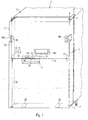
- the container 1 shown in perspective and schematically in FIG. 1, which is in the Specifically can be an insulated container, includes a housing 3, which can be closed by means of a door 5.
- the door is on hinge elements 7 on the housing hinged.
- the hinge elements 7 are articulated on the one hand with the door and on the other hand hinged to the housing 3 and define axis of rotation A, A '. This The way in which the door is articulated enables the door to be opened up to one Angle of 270 °, d. H. that the door is in the maximum pivoted state on the relevant one adjacent long side of the container 3 can rest.
- the locking device 9 comprises in the embodiment shown in FIG. 1 a rotatable axis 11 which is mounted essentially horizontally in the door 5.
- locking elements 13 are provided in the outer side regions of the door are rotatably connected to the axis 11.
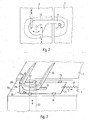
- the locking elements 13 include Arms, which are provided in the locked state in the side walls of the housing reach behind complementary locking elements. This situation is in Fig. 2 shown schematically.
- This partially broken side view shows the locking elements 13 in the locked position, in which the arms 15 the complementary Reach behind locking elements 17.
- the complementary locking elements can be as simple, in the side walls of the housing essentially horizontally extending bolts or bearing bushes.
- An actuator 12 is provided on the axis for rotating the axis 11, which is articulated to the axle.
- the Axis 11 a short arm 11 a may be provided, on which the actuating element 12 is articulated.
- the pivot axis of the actuator 12 can be locked Position, for example, at an angle of 45 ° to the plane of the door surface and run perpendicular to axis 11.
- the actuating element 12 is in its rest position essentially parallel to the axis 11. Through the recess 14 in the front the door 5 can be ensured that the actuating element 12 in its Rest position does not protrude beyond the surface of door 5. This allows the container be placed close together without the risk of damage.
- the actuator 12 For pressing the Locking device, the actuator 12 as far from its rest position pivoted out until there is sufficient lever arm for rotating the axis 11. After rotation has taken place, the actuating element 12 can be returned to its axis 11 parallel position can be pivoted back. Since the rotational movement of the axis 11 at swung out actuator 12 takes place, the recess 14 with respect their space requirements are very small. This results in the Advantage of only a small area of the door, in which a reduced thermal resistance is given and in which the mechanical stability is lower than in the rest Areas of the door, unless additional (mostly complex) measures are taken become.
- the actuating element 12 can also be by means of a resilient element (not shown) towards its starting position, so that after a Swiveling out of its initial position is automatically returned to it, when the operator releases the actuator.
- a fixing element 16 can be arranged in a fixed manner in the recess 14.
- the Fixing element 16 is designed such that it is both from the actuating element 12 in the locked position and the unlocked position of the locking device is engaged when the actuating element is in its initial position (in which it is preferably held by the resilient element).
- the fixing element 16 may be substantially triangular, the triangular Element is firmly arranged with its tip in the recess 14.
- the investment areas the or edges of the fixing element can be slightly curved inwards, to securely fix the actuator.
- the actuator 12 must be Opening are pivoted out until it is free relative to the fixing element 16 lies and a rotation of the axis 11 is possible.
- it can Actuator then active again and / or inward due to the spring loading be pivoted.
- the rotation of the axis 11 must be such Angles are made so that in the angular position reached a complete inward pivoting of the actuating element 12 is possible.
- In intermediate positions would the actuator with its inner wall on the front face of the Fixing element rest so that it is not brought into its starting position can. This immediately shows an operator that the unlocked or locked position the locking device was not reached correctly and a correction is required is.
- handles 19a, 19b to transport the container, for example on rollers 21 pull or lift.
- the handles 19a, 19b are also designed so that they do not have the outer contour or the outer walls of the housing 3 or Project door 5 to allow several containers 1 to be placed close to you.
- push rods 23 can be provided with their free ones Ends in the locked state in a complementary arranged on the housing 3 Intervene locking element or receiving element.
- the push rods can with their respective inner ends the locking element 13, each connected eccentrically to the axis 11. at a rotation of the axis 11 for the transfer of the locking elements 13 in the unlocked position, for example at an angle of approximately 60 ° to 90 °, the Push rods 23 moved inwards (in relation to the door) and in this way also transferred to the unlocked state.
- the angle of rotation is preferably determined so that the arms 15 of the rotatable locking elements 13 in the unlocked position not over the inner wall or the outer dimensions or outer contour of the door 5 protrude.
- corresponding push rods can also be attached to the further locking element 13 may be provided on the hinge side of the door 5 in this way additionally lock the door at these positions.
- corresponding push rods at any position on the horizontal axis 11 to be arranged, for example additionally in the middle of the door or the axis 11.
- the push rods do not have to, as is shown schematically in FIG. 1 for reasons of simplicity shown to be straight. Rather, they can be practically any Have shape.
- the housing 3 can in the area of the lower edge of the door 5 one or more ramp ramps 26 have. These serve to tolerances or a game of articulation the door, which may arise over time from the use of the container can compensate. "The door hangs a little too far in relation to the housing below or at an angle, the lower edge of the door slides onto the inclined or curved ones Surfaces of the ramp ramps 26 and thus, despite the existing Game or "hanging" in a correct closing position in which the locking elements easily and correctly in the complementary locking elements intervention.
- Fig. 3 shows the locking of the door 5 at the upper left corner of the container 1 in Fig. 1 in an enlarged perspective view.
- the complementary locking element or receiving element 25 is formed by means of a substantially U-shaped part, which on the Top of the housing 3 is fixed.
- the push rod 23 engages in the locked State with its free end in the receiving area 27 through the U-shaped Part formed with its area protruding beyond the front of the housing becomes.
- a blocking device 29 is arranged on the top face 5a of the door 5, via which the free end of the push rod 23 (at least in the locked State) protrudes.
- the blocking element 31 is on the upper end face 5a corresponding guide elements 35 slidably held.
- the spring 33 is in FIG. 3 designed as a tension spring. However, it could of course also be used as a compression spring trained and accordingly attack the blocking element 31, namely so that the blocking element is brought into the blocked position when the door 5 opens.
- the blocking element 31 has one Breakthrough 37 through which the free end of the in the locked state Push rod 23 protrudes.
- the blocking element 31 has a vertically angled portion 31 a on, the U-shaped receiving element 25 in the locked state on the left leg is applied.
- the movement of the blocking element 31 to the right must include a path that is sufficient to the free end of the push rod 23 in terms of its locking movement to block.
- the push rod 23 is only moved inwards until this except Engagement with the receiving element 25 and in this position still on the top of the locking element 31 protrudes.
- the blocking element 31 can be designed such that the opening 37 the release movement, d. H. allows the blocking element 31 to slide to the right, even if that free end of the push rod 23 continues to protrude through the opening.
- the breakthrough can be designed so far that it is compatible with a corresponding Height up to the upwardly angled area 31 a of the blocking element 31 continues.
- the blocking device can then be designed such that the blocking element is shifted far to the right until the angled area 31 a in the area of upper end of the free end of the push rod 23 comes to rest. An inadmissible wide upward movement of the push rod 23 is then through the part of the opening 23 blocks, which extends into the angled region 31 a of the blocking element 31 stretched in.
- the blocking element 31 acts against the force of the spring 33 shifted to the left as soon as the end face of the angled portion 31a the receiving element 25 comes into contact.
- the guide surface 25a is so explained that when the door is closed again, the blocking element 31 without excessive force when closing the door is shifted to the left.
- the Blocking element 31 is designed with respect to the opening 37 so that a Locking the device, i. H. an outward movement of the push rods 23 only is then made possible when the free end of the push rod 23 is in the region of Receiving area 27 is formed by the receiving element 25. In order to will damage the door or the container as a result of closing the door safely avoided with the locking device locked at the same time.
- Pre-fixing elements 31b, 25b can be provided on the partial area 31a and on the guide surface 25a be provided, which are formed, for example, as raised embossments in these parts could be.
- the pre-fixing elements can of course also be used as stand-alone units Elements be formed.
- the pre-fixing elements 31b, 25b are designed such that when the door is closed 5 the door is locked or pre-fixed in a position in which the blocking device the locking device has already released and preferably in the upon actuation of the locking device, locking and final The door is closed (by the remaining small opening angle) without the operator would have to actively close the door.
Landscapes
- Engineering & Computer Science (AREA)
- Mechanical Engineering (AREA)
- Structural Engineering (AREA)
- Closures For Containers (AREA)
- Lock And Its Accessories (AREA)
- Table Devices Or Equipment (AREA)
- Packages (AREA)
Applications Claiming Priority (2)
| Application Number | Priority Date | Filing Date | Title |
|---|---|---|---|
| DE10255829 | 2002-11-29 | ||
| DE10255829A DE10255829B4 (de) | 2002-11-29 | 2002-11-29 | Verriegelungsvorrichtung für einen Behälter, insbesondere Isolierbehälter |
Publications (3)
| Publication Number | Publication Date |
|---|---|
| EP1424461A2 true EP1424461A2 (fr) | 2004-06-02 |
| EP1424461A3 EP1424461A3 (fr) | 2005-09-21 |
| EP1424461B1 EP1424461B1 (fr) | 2008-03-19 |
Family
ID=32240523
Family Applications (1)
| Application Number | Title | Priority Date | Filing Date |
|---|---|---|---|
| EP03027414A Expired - Lifetime EP1424461B1 (fr) | 2002-11-29 | 2003-11-27 | Conteneur, notamment conteneur isotherme |
Country Status (3)
| Country | Link |
|---|---|
| EP (1) | EP1424461B1 (fr) |
| AT (1) | ATE389770T1 (fr) |
| DE (2) | DE10255829B4 (fr) |
Cited By (1)
| Publication number | Priority date | Publication date | Assignee | Title |
|---|---|---|---|---|
| FR2881453A1 (fr) * | 2005-02-01 | 2006-08-04 | Ferco Int Usine Ferrures | Dispositif d'anti-fausse manoeuvre pour ferrure de verrouillage |
Family Cites Families (12)
| Publication number | Priority date | Publication date | Assignee | Title |
|---|---|---|---|---|
| US608893A (en) * | 1898-08-09 | Refrigerator-door | ||
| GB228621A (en) * | 1923-11-07 | 1925-02-09 | James Edward Wilson | Improvements in and relating to means for securing closed with pressure the doors ofcold storage chambers large or small |
| FR127455A (fr) * | 1967-11-08 | |||
| DE1807388A1 (de) * | 1968-11-07 | 1970-05-27 | Guenter Mueller | Container mit abnehmbarem Dach |
| JPS5252759A (en) * | 1975-10-24 | 1977-04-27 | Mitsuo Oosumi | Laterally openable door |
| IT1043336B (it) * | 1975-12-01 | 1980-02-20 | Viro Innocento S P A | Serratura di sicurezza |
| DE8130668U1 (de) * | 1981-10-21 | 1982-05-06 | Friott Metall- und Maschinenbau GmbH, 3436 Hessisch Lichtenau | "tresor, insbesondere moebel- oder wandtresor" |
| US4784414A (en) * | 1987-08-28 | 1988-11-15 | Coachmen Industries, Inc. | Latch mechanism |
| FR2683847B1 (fr) * | 1991-11-15 | 1994-03-18 | Ferco Internal Usine Ferrures Ba | Ferrure de verrouillage pour porte, fenetre ou analogue comportant des organes de verrouillage a rappel elastique en position verrouillee. |
| US5375894A (en) * | 1992-10-08 | 1994-12-27 | Southco, Inc. | Slide lock fastener |
| DE29506799U1 (de) * | 1995-04-21 | 1996-08-22 | Niemann, Hans Dieter, 50169 Kerpen | Vorrichtung an einem Türschloß |
| JP2001208464A (ja) * | 2000-01-31 | 2001-08-03 | Sanden Corp | 保冷庫 |
-
2002
- 2002-11-29 DE DE10255829A patent/DE10255829B4/de not_active Expired - Fee Related
-
2003
- 2003-11-27 DE DE50309405T patent/DE50309405D1/de not_active Expired - Lifetime
- 2003-11-27 AT AT03027414T patent/ATE389770T1/de not_active IP Right Cessation
- 2003-11-27 EP EP03027414A patent/EP1424461B1/fr not_active Expired - Lifetime
Cited By (1)
| Publication number | Priority date | Publication date | Assignee | Title |
|---|---|---|---|---|
| FR2881453A1 (fr) * | 2005-02-01 | 2006-08-04 | Ferco Int Usine Ferrures | Dispositif d'anti-fausse manoeuvre pour ferrure de verrouillage |
Also Published As
| Publication number | Publication date |
|---|---|
| EP1424461B1 (fr) | 2008-03-19 |
| EP1424461A3 (fr) | 2005-09-21 |
| DE10255829B4 (de) | 2007-06-06 |
| DE10255829A1 (de) | 2004-06-24 |
| DE50309405D1 (de) | 2008-04-30 |
| ATE389770T1 (de) | 2008-04-15 |
Similar Documents
| Publication | Publication Date | Title |
|---|---|---|
| DE4334097C2 (de) | Gleitbefestigung | |
| WO1990005827A1 (fr) | Passe-plat s'inserant dans des portes et des murs | |
| DE112010000872B4 (de) | Container | |
| DE2204427B2 (de) | Beschlag fuer einen heb- und schiebbaren fluegel eines fensters, einer tuere o.dgl. | |
| WO2013020154A1 (fr) | Conteneur de transport | |
| DE60012385T2 (de) | Türklemmschlossvorrichtung | |
| DE102014109988B4 (de) | Kranken- und/oder Pflegebett und ein Seitengitter | |
| EP1424461B1 (fr) | Conteneur, notamment conteneur isotherme | |
| EP0090956B2 (fr) | Ferrure pour une fenêtre, une porte ou analogues | |
| EP3015340B1 (fr) | Conteneur roulant dote de paroi laterale amovible | |
| DE2731163C3 (de) | Doppelfenster mit zwei an einem Stockrahmen gelagerten, wahlweise drehbaren oder kippbaren Flügelrahmen | |
| DE102011003655B4 (de) | Verriegelungssystem für eine Tischtennisplatte | |
| EP2394117A2 (fr) | Appareil frigorifique comprenant un support pour aliments refrigeres reglable en hauteur | |
| DE10222998B4 (de) | Rückwandtür mit Türsicherungselementen für ein Lastfahrzeug | |
| DE2630375C2 (de) | Türanordnung, insbesondere für Behälter, Behälterwagen o.dgl. | |
| DE69209731T2 (de) | Güterwagen mit verschiebbarer Abdeckung | |
| DE3919349C2 (fr) | ||
| AT304842B (de) | Ausstell- und Verriegelungsvorrichtung für Fenster | |
| DE3345119A1 (de) | Vorrichtung zum verriegeln von tueren oder fenstern | |
| DE2639304A1 (de) | Schubladenschrank zum einbau in fahrzeuge | |
| EP0777986B1 (fr) | Chariot de distribution de repas | |
| DE2611077C2 (de) | Verschluß für klapp- oder schwenkbare Bordwandkonstruktionen | |
| DE2728401C2 (de) | Tür, insbesondere Containertür | |
| DE4419779B4 (de) | Türsicherungsvorrichtung | |
| DE60201710T2 (de) | Untere Verriegelungsvorrichtung für Schiebewände von Einsenbahngüterwagen |
Legal Events
| Date | Code | Title | Description |
|---|---|---|---|
| PUAI | Public reference made under article 153(3) epc to a published international application that has entered the european phase |
Free format text: ORIGINAL CODE: 0009012 |
|
| AK | Designated contracting states |
Kind code of ref document: A2 Designated state(s): AT BE BG CH CY CZ DE DK EE ES FI FR GB GR HU IE IT LI LU MC NL PT RO SE SI SK TR |
|
| AX | Request for extension of the european patent |
Extension state: AL LT LV MK |
|
| PUAL | Search report despatched |
Free format text: ORIGINAL CODE: 0009013 |
|
| AK | Designated contracting states |
Kind code of ref document: A3 Designated state(s): AT BE BG CH CY CZ DE DK EE ES FI FR GB GR HU IE IT LI LU MC NL PT RO SE SI SK TR |
|
| AX | Request for extension of the european patent |
Extension state: AL LT LV MK |
|
| 17P | Request for examination filed |
Effective date: 20050920 |
|
| AKX | Designation fees paid |
Designated state(s): AT BE BG CH CY CZ DE DK EE ES FI FR GB GR HU IE IT LI LU MC NL PT RO SE SI SK TR |
|
| GRAP | Despatch of communication of intention to grant a patent |
Free format text: ORIGINAL CODE: EPIDOSNIGR1 |
|
| RTI1 | Title (correction) |
Free format text: CONTAINER, IN PARTICULAR INSULATED CONTAINER |
|
| GRAS | Grant fee paid |
Free format text: ORIGINAL CODE: EPIDOSNIGR3 |
|
| GRAA | (expected) grant |
Free format text: ORIGINAL CODE: 0009210 |
|
| AK | Designated contracting states |
Kind code of ref document: B1 Designated state(s): AT BE BG CH CY CZ DE DK EE ES FI FR GB GR HU IE IT LI LU MC NL PT RO SE SI SK TR |
|
| REG | Reference to a national code |
Ref country code: GB Ref legal event code: FG4D Free format text: NOT ENGLISH |
|
| REG | Reference to a national code |
Ref country code: CH Ref legal event code: EP |
|
| REF | Corresponds to: |
Ref document number: 50309405 Country of ref document: DE Date of ref document: 20080430 Kind code of ref document: P |
|
| REG | Reference to a national code |
Ref country code: IE Ref legal event code: FG4D Free format text: LANGUAGE OF EP DOCUMENT: GERMAN |
|
| PG25 | Lapsed in a contracting state [announced via postgrant information from national office to epo] |
Ref country code: FI Free format text: LAPSE BECAUSE OF FAILURE TO SUBMIT A TRANSLATION OF THE DESCRIPTION OR TO PAY THE FEE WITHIN THE PRESCRIBED TIME-LIMIT Effective date: 20080319 |
|
| NLV1 | Nl: lapsed or annulled due to failure to fulfill the requirements of art. 29p and 29m of the patents act | ||
| PG25 | Lapsed in a contracting state [announced via postgrant information from national office to epo] |
Ref country code: SI Free format text: LAPSE BECAUSE OF FAILURE TO SUBMIT A TRANSLATION OF THE DESCRIPTION OR TO PAY THE FEE WITHIN THE PRESCRIBED TIME-LIMIT Effective date: 20080319 |
|
| REG | Reference to a national code |
Ref country code: IE Ref legal event code: FD4D |
|
| PG25 | Lapsed in a contracting state [announced via postgrant information from national office to epo] |
Ref country code: SK Free format text: LAPSE BECAUSE OF FAILURE TO SUBMIT A TRANSLATION OF THE DESCRIPTION OR TO PAY THE FEE WITHIN THE PRESCRIBED TIME-LIMIT Effective date: 20080319 Ref country code: CZ Free format text: LAPSE BECAUSE OF FAILURE TO SUBMIT A TRANSLATION OF THE DESCRIPTION OR TO PAY THE FEE WITHIN THE PRESCRIBED TIME-LIMIT Effective date: 20080319 Ref country code: ES Free format text: LAPSE BECAUSE OF FAILURE TO SUBMIT A TRANSLATION OF THE DESCRIPTION OR TO PAY THE FEE WITHIN THE PRESCRIBED TIME-LIMIT Effective date: 20080630 Ref country code: SE Free format text: LAPSE BECAUSE OF FAILURE TO SUBMIT A TRANSLATION OF THE DESCRIPTION OR TO PAY THE FEE WITHIN THE PRESCRIBED TIME-LIMIT Effective date: 20080619 Ref country code: PT Free format text: LAPSE BECAUSE OF FAILURE TO SUBMIT A TRANSLATION OF THE DESCRIPTION OR TO PAY THE FEE WITHIN THE PRESCRIBED TIME-LIMIT Effective date: 20080826 |
|
| PG25 | Lapsed in a contracting state [announced via postgrant information from national office to epo] |
Ref country code: NL Free format text: LAPSE BECAUSE OF FAILURE TO SUBMIT A TRANSLATION OF THE DESCRIPTION OR TO PAY THE FEE WITHIN THE PRESCRIBED TIME-LIMIT Effective date: 20080319 Ref country code: RO Free format text: LAPSE BECAUSE OF FAILURE TO SUBMIT A TRANSLATION OF THE DESCRIPTION OR TO PAY THE FEE WITHIN THE PRESCRIBED TIME-LIMIT Effective date: 20080319 |
|
| ET | Fr: translation filed | ||
| PLBE | No opposition filed within time limit |
Free format text: ORIGINAL CODE: 0009261 |
|
| STAA | Information on the status of an ep patent application or granted ep patent |
Free format text: STATUS: NO OPPOSITION FILED WITHIN TIME LIMIT |
|
| PG25 | Lapsed in a contracting state [announced via postgrant information from national office to epo] |
Ref country code: IE Free format text: LAPSE BECAUSE OF FAILURE TO SUBMIT A TRANSLATION OF THE DESCRIPTION OR TO PAY THE FEE WITHIN THE PRESCRIBED TIME-LIMIT Effective date: 20080319 Ref country code: DK Free format text: LAPSE BECAUSE OF FAILURE TO SUBMIT A TRANSLATION OF THE DESCRIPTION OR TO PAY THE FEE WITHIN THE PRESCRIBED TIME-LIMIT Effective date: 20080319 |
|
| 26N | No opposition filed |
Effective date: 20081222 |
|
| PG25 | Lapsed in a contracting state [announced via postgrant information from national office to epo] |
Ref country code: EE Free format text: LAPSE BECAUSE OF FAILURE TO SUBMIT A TRANSLATION OF THE DESCRIPTION OR TO PAY THE FEE WITHIN THE PRESCRIBED TIME-LIMIT Effective date: 20080319 Ref country code: BG Free format text: LAPSE BECAUSE OF FAILURE TO SUBMIT A TRANSLATION OF THE DESCRIPTION OR TO PAY THE FEE WITHIN THE PRESCRIBED TIME-LIMIT Effective date: 20080619 |
|
| BERE | Be: lapsed |
Owner name: GEBHARDT TRANSPORT- UND LAGERSYSTEME G.M.B.H. Effective date: 20081130 |
|
| PG25 | Lapsed in a contracting state [announced via postgrant information from national office to epo] |
Ref country code: MC Free format text: LAPSE BECAUSE OF NON-PAYMENT OF DUE FEES Effective date: 20081130 |
|
| REG | Reference to a national code |
Ref country code: CH Ref legal event code: PL |
|
| GBPC | Gb: european patent ceased through non-payment of renewal fee |
Effective date: 20081127 |
|
| PG25 | Lapsed in a contracting state [announced via postgrant information from national office to epo] |
Ref country code: CY Free format text: LAPSE BECAUSE OF FAILURE TO SUBMIT A TRANSLATION OF THE DESCRIPTION OR TO PAY THE FEE WITHIN THE PRESCRIBED TIME-LIMIT Effective date: 20080319 Ref country code: BE Free format text: LAPSE BECAUSE OF NON-PAYMENT OF DUE FEES Effective date: 20081130 |
|
| PG25 | Lapsed in a contracting state [announced via postgrant information from national office to epo] |
Ref country code: CH Free format text: LAPSE BECAUSE OF NON-PAYMENT OF DUE FEES Effective date: 20081130 Ref country code: LI Free format text: LAPSE BECAUSE OF NON-PAYMENT OF DUE FEES Effective date: 20081130 |
|
| PG25 | Lapsed in a contracting state [announced via postgrant information from national office to epo] |
Ref country code: GB Free format text: LAPSE BECAUSE OF NON-PAYMENT OF DUE FEES Effective date: 20081127 |
|
| PG25 | Lapsed in a contracting state [announced via postgrant information from national office to epo] |
Ref country code: AT Free format text: LAPSE BECAUSE OF NON-PAYMENT OF DUE FEES Effective date: 20081127 |
|
| PG25 | Lapsed in a contracting state [announced via postgrant information from national office to epo] |
Ref country code: LU Free format text: LAPSE BECAUSE OF NON-PAYMENT OF DUE FEES Effective date: 20081127 Ref country code: HU Free format text: LAPSE BECAUSE OF FAILURE TO SUBMIT A TRANSLATION OF THE DESCRIPTION OR TO PAY THE FEE WITHIN THE PRESCRIBED TIME-LIMIT Effective date: 20080920 |
|
| PG25 | Lapsed in a contracting state [announced via postgrant information from national office to epo] |
Ref country code: TR Free format text: LAPSE BECAUSE OF FAILURE TO SUBMIT A TRANSLATION OF THE DESCRIPTION OR TO PAY THE FEE WITHIN THE PRESCRIBED TIME-LIMIT Effective date: 20080319 |
|
| PG25 | Lapsed in a contracting state [announced via postgrant information from national office to epo] |
Ref country code: GR Free format text: LAPSE BECAUSE OF FAILURE TO SUBMIT A TRANSLATION OF THE DESCRIPTION OR TO PAY THE FEE WITHIN THE PRESCRIBED TIME-LIMIT Effective date: 20080620 |
|
| PGFP | Annual fee paid to national office [announced via postgrant information from national office to epo] |
Ref country code: IT Payment date: 20121123 Year of fee payment: 10 |
|
| PGFP | Annual fee paid to national office [announced via postgrant information from national office to epo] |
Ref country code: FR Payment date: 20121217 Year of fee payment: 10 |
|
| PGFP | Annual fee paid to national office [announced via postgrant information from national office to epo] |
Ref country code: DE Payment date: 20140131 Year of fee payment: 11 |
|
| REG | Reference to a national code |
Ref country code: FR Ref legal event code: ST Effective date: 20140731 |
|
| PG25 | Lapsed in a contracting state [announced via postgrant information from national office to epo] |
Ref country code: IT Free format text: LAPSE BECAUSE OF NON-PAYMENT OF DUE FEES Effective date: 20131127 |
|
| PG25 | Lapsed in a contracting state [announced via postgrant information from national office to epo] |
Ref country code: FR Free format text: LAPSE BECAUSE OF NON-PAYMENT OF DUE FEES Effective date: 20131202 |
|
| REG | Reference to a national code |
Ref country code: DE Ref legal event code: R119 Ref document number: 50309405 Country of ref document: DE |
|
| PG25 | Lapsed in a contracting state [announced via postgrant information from national office to epo] |
Ref country code: DE Free format text: LAPSE BECAUSE OF NON-PAYMENT OF DUE FEES Effective date: 20150602 |