EP1424462A2 - Bras de support pour un couvercle de coffre-fort - Google Patents
Bras de support pour un couvercle de coffre-fort Download PDFInfo
- Publication number
- EP1424462A2 EP1424462A2 EP20030026878 EP03026878A EP1424462A2 EP 1424462 A2 EP1424462 A2 EP 1424462A2 EP 20030026878 EP20030026878 EP 20030026878 EP 03026878 A EP03026878 A EP 03026878A EP 1424462 A2 EP1424462 A2 EP 1424462A2
- Authority
- EP
- European Patent Office
- Prior art keywords
- support arm
- bracket
- safe
- opening
- arm assembly
- Prior art date
- Legal status (The legal status is an assumption and is not a legal conclusion. Google has not performed a legal analysis and makes no representation as to the accuracy of the status listed.)
- Withdrawn
Links
- 238000000034 method Methods 0.000 claims description 9
- 230000009970 fire resistant effect Effects 0.000 claims description 7
- 239000011810 insulating material Substances 0.000 claims 4
- 230000000712 assembly Effects 0.000 description 3
- 238000000429 assembly Methods 0.000 description 3
- 238000005304 joining Methods 0.000 description 3
- 230000005484 gravity Effects 0.000 description 2
- 239000012774 insulation material Substances 0.000 description 2
- 238000004519 manufacturing process Methods 0.000 description 2
- 238000003860 storage Methods 0.000 description 2
- 238000010276 construction Methods 0.000 description 1
- 239000000203 mixture Substances 0.000 description 1
- 238000000926 separation method Methods 0.000 description 1
Images



Classifications
-
- E—FIXED CONSTRUCTIONS
- E05—LOCKS; KEYS; WINDOW OR DOOR FITTINGS; SAFES
- E05G—SAFES OR STRONG-ROOMS FOR VALUABLES; BANK PROTECTION DEVICES; SAFETY TRANSACTION PARTITIONS
- E05G1/00—Safes or strong-rooms for valuables
- E05G1/005—Portable strong boxes, e.g. which may be fixed to a wall or the like
-
- E—FIXED CONSTRUCTIONS
- E05—LOCKS; KEYS; WINDOW OR DOOR FITTINGS; SAFES
- E05C—BOLTS OR FASTENING DEVICES FOR WINGS, SPECIALLY FOR DOORS OR WINDOWS
- E05C17/00—Devices for holding wings open; Devices for limiting opening of wings or for holding wings open by a movable member extending between frame and wing; Braking devices, stops or buffers, combined therewith
- E05C17/02—Devices for holding wings open; Devices for limiting opening of wings or for holding wings open by a movable member extending between frame and wing; Braking devices, stops or buffers, combined therewith by mechanical means
- E05C17/04—Devices for holding wings open; Devices for limiting opening of wings or for holding wings open by a movable member extending between frame and wing; Braking devices, stops or buffers, combined therewith by mechanical means with a movable bar or equivalent member extending between frame and wing
- E05C17/12—Devices for holding wings open; Devices for limiting opening of wings or for holding wings open by a movable member extending between frame and wing; Braking devices, stops or buffers, combined therewith by mechanical means with a movable bar or equivalent member extending between frame and wing consisting of a single rod
- E05C17/20—Devices for holding wings open; Devices for limiting opening of wings or for holding wings open by a movable member extending between frame and wing; Braking devices, stops or buffers, combined therewith by mechanical means with a movable bar or equivalent member extending between frame and wing consisting of a single rod sliding through a guide
-
- Y—GENERAL TAGGING OF NEW TECHNOLOGICAL DEVELOPMENTS; GENERAL TAGGING OF CROSS-SECTIONAL TECHNOLOGIES SPANNING OVER SEVERAL SECTIONS OF THE IPC; TECHNICAL SUBJECTS COVERED BY FORMER USPC CROSS-REFERENCE ART COLLECTIONS [XRACs] AND DIGESTS
- Y10—TECHNICAL SUBJECTS COVERED BY FORMER USPC
- Y10S—TECHNICAL SUBJECTS COVERED BY FORMER USPC CROSS-REFERENCE ART COLLECTIONS [XRACs] AND DIGESTS
- Y10S292/00—Closure fasteners
- Y10S292/11—Cover fasteners
-
- Y—GENERAL TAGGING OF NEW TECHNOLOGICAL DEVELOPMENTS; GENERAL TAGGING OF CROSS-SECTIONAL TECHNOLOGIES SPANNING OVER SEVERAL SECTIONS OF THE IPC; TECHNICAL SUBJECTS COVERED BY FORMER USPC CROSS-REFERENCE ART COLLECTIONS [XRACs] AND DIGESTS
- Y10—TECHNICAL SUBJECTS COVERED BY FORMER USPC
- Y10T—TECHNICAL SUBJECTS COVERED BY FORMER US CLASSIFICATION
- Y10T292/00—Closure fasteners
- Y10T292/28—Extension link
-
- Y—GENERAL TAGGING OF NEW TECHNOLOGICAL DEVELOPMENTS; GENERAL TAGGING OF CROSS-SECTIONAL TECHNOLOGIES SPANNING OVER SEVERAL SECTIONS OF THE IPC; TECHNICAL SUBJECTS COVERED BY FORMER USPC CROSS-REFERENCE ART COLLECTIONS [XRACs] AND DIGESTS
- Y10—TECHNICAL SUBJECTS COVERED BY FORMER USPC
- Y10T—TECHNICAL SUBJECTS COVERED BY FORMER US CLASSIFICATION
- Y10T292/00—Closure fasteners
- Y10T292/28—Extension link
- Y10T292/285—Notched bar
-
- Y—GENERAL TAGGING OF NEW TECHNOLOGICAL DEVELOPMENTS; GENERAL TAGGING OF CROSS-SECTIONAL TECHNOLOGIES SPANNING OVER SEVERAL SECTIONS OF THE IPC; TECHNICAL SUBJECTS COVERED BY FORMER USPC CROSS-REFERENCE ART COLLECTIONS [XRACs] AND DIGESTS
- Y10—TECHNICAL SUBJECTS COVERED BY FORMER USPC
- Y10T—TECHNICAL SUBJECTS COVERED BY FORMER US CLASSIFICATION
- Y10T292/00—Closure fasteners
- Y10T292/28—Extension link
- Y10T292/285—Notched bar
- Y10T292/288—Swinging catch
-
- Y—GENERAL TAGGING OF NEW TECHNOLOGICAL DEVELOPMENTS; GENERAL TAGGING OF CROSS-SECTIONAL TECHNOLOGIES SPANNING OVER SEVERAL SECTIONS OF THE IPC; TECHNICAL SUBJECTS COVERED BY FORMER USPC CROSS-REFERENCE ART COLLECTIONS [XRACs] AND DIGESTS
- Y10—TECHNICAL SUBJECTS COVERED BY FORMER USPC
- Y10T—TECHNICAL SUBJECTS COVERED BY FORMER US CLASSIFICATION
- Y10T292/00—Closure fasteners
- Y10T292/28—Extension link
- Y10T292/289—Slotted bar
-
- Y—GENERAL TAGGING OF NEW TECHNOLOGICAL DEVELOPMENTS; GENERAL TAGGING OF CROSS-SECTIONAL TECHNOLOGIES SPANNING OVER SEVERAL SECTIONS OF THE IPC; TECHNICAL SUBJECTS COVERED BY FORMER USPC CROSS-REFERENCE ART COLLECTIONS [XRACs] AND DIGESTS
- Y10—TECHNICAL SUBJECTS COVERED BY FORMER USPC
- Y10T—TECHNICAL SUBJECTS COVERED BY FORMER US CLASSIFICATION
- Y10T292/00—Closure fasteners
- Y10T292/28—Extension link
- Y10T292/289—Slotted bar
- Y10T292/293—Swinging catch
-
- Y—GENERAL TAGGING OF NEW TECHNOLOGICAL DEVELOPMENTS; GENERAL TAGGING OF CROSS-SECTIONAL TECHNOLOGIES SPANNING OVER SEVERAL SECTIONS OF THE IPC; TECHNICAL SUBJECTS COVERED BY FORMER USPC CROSS-REFERENCE ART COLLECTIONS [XRACs] AND DIGESTS
- Y10—TECHNICAL SUBJECTS COVERED BY FORMER USPC
- Y10T—TECHNICAL SUBJECTS COVERED BY FORMER US CLASSIFICATION
- Y10T292/00—Closure fasteners
- Y10T292/28—Extension link
- Y10T292/299—Slotted keeper
-
- Y—GENERAL TAGGING OF NEW TECHNOLOGICAL DEVELOPMENTS; GENERAL TAGGING OF CROSS-SECTIONAL TECHNOLOGIES SPANNING OVER SEVERAL SECTIONS OF THE IPC; TECHNICAL SUBJECTS COVERED BY FORMER USPC CROSS-REFERENCE ART COLLECTIONS [XRACs] AND DIGESTS
- Y10—TECHNICAL SUBJECTS COVERED BY FORMER USPC
- Y10T—TECHNICAL SUBJECTS COVERED BY FORMER US CLASSIFICATION
- Y10T292/00—Closure fasteners
- Y10T292/65—Braces
Definitions
- Our invention deals with an easily installed support arm assembly for use in holding up the lid of a top-opening safe.
- the first group involves designs wherein a generally linear brace member is pivotally mounted to the lid of a top opening structure with its opposite end slidably mounted to the base of the structure via a connecting member engaged in a linear slotted element running parallel to a side edge of the structure.
- a connecting member engaged in a linear slotted element running parallel to a side edge of the structure.
- U.S. Patent No. 406,595 discloses a trunk support arm or brace that is pivotally mounted to the lid with its opposite end slidably mounted via a member engaging a slot formed parallel to the side edge of the trunk opening.
- 1,096,964 likewise has a brace pivotally mounted to the lid with the opposite end of the brace being slidably mounted via a member engaged in a slot formed parallel to the side edge of the trunk opening.
- the slot faces the lid rather than the interior of the trunk (as in Patent No. 406,595).
- the slot also has a shoulder allowing the brace to be temporarily affixed in an upright position.
- U.S. Patent No. 1,986,307 teaches a variation wherein the slot can be mounted on the lid as well as on the base with the brace being pivotally mounted to the base rather than the lid.
- the second group of patents involves designs wherein a generally linear support arm or brace member is pivotally mounted to the lid of a top opening structure with its opposite end sliding through a slot or opening in a bracket affixed to the side edge of the structure's base.
- the brace generally remains transverse to the slot or opening as the top is opened or closed.
- the brace is generally parallel to the slotted element when the top is closed and moves into a more-or-less transverse position when the top is open.
- U.S. Patent Nos. 1,303,441 and 5,570,493 provide examples of designs from the second group.
- a brace member is pivotally mounted to the lid of a top opening structure.
- the bodies and lids of our company's fire-resistant storage containers are constructed by joining internal and external shells together so that they form a mold that can be filled with insulation material.
- the insulation material itself is generally a concrete mixture that solidifies in the mold formed by the internal and external shells.
- the lid and body of our safes are relatively heavy.
- any support arm assembly used in holding the lid of the safe in an open position be sturdy as well as being easily released and compact.
- the components of the assembly be simple to use and manufacture, that the assembly be easy to put together, and that the assembly be easy to affix to the interior of the safe's body and lid. All of these factors promote customer convenience and/or minimize the time and expense necessary for manufacture.
- a support arm assembly for connection between a safe's lid and base with only two main parts. First, it has a bracket for connection to the safe's base. Second, it has a linear support arm that connects between the bracket and the lid.
- the bracket has a generally "L" shaped cross-section with a side face adapted for placement adjacent to (and for connection to) the inner side of a safe's base proximate its upper edge.
- the other face of the "L" shaped bracket serves as its upward facing side and is provided with a linear slot that is parallel to the side of the safe when the bracket is mounted.
- the linear support arm has a generally flat planar configuration that is adapted for placement through the linear slot in the bracket. When in place, it is transverse to the upward facing side of the bracket and is slidable in the slot parallel to the side face of the bracket.
- the linear support arm has an upper end with a lid connection member pivotally connected thereto. This lid connection member is adapted to pivotally connect the upper end of the linear support arm to a safe lid.
- the lower end or the linear support arm has a bend that prevents it from being withdrawn from the slot once it is put into place (without the need for any further anchor or connecting member to prevent its withdrawal).
- This bend is also critical to the convenience and efficiency of our invention in another way. It allows the brace to be assembled in functional permanent cooperative relationship to the bracket with great ease and simplicity and without any separate fastening means. This can be done in two ways. First, by sliding the bend through the bracket slot after the bracket is fastened to the side of the safe and then fastening the top of the brace to the safe lid. (After the latter operation is completed, the brace can no longer be withdrawn from the bracket.) Second, by sliding the bend through the bracket before fastening the bracket to the side of the safe. After this, the bracket and the other end of the brace can be connected to their appropriate locations on the safe.
- the lower end of the linear support arm also has an abrupt edged notch adjacent the bend in the lower edge of the linear support arm.
- This notch is adapted to interlock with the slot by dropping into the slot (by gravity) when the box lid is opened.
- This simple and efficient method for bracing the lid also allows the lid to be lowered with great ease by merely moving the linear support arm forward slightly towards the front of the safe. In doing this, the notch no longer interlocks with the slot, and the lid can be allowed to drop into closed position.
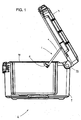
- Support arm assembly (denoted generally by arrow 1) is ideal for use with a portable fireproof safe (denoted generally by arrow 2) of the type illustrated in FIG. 1.
- Safe 2 has a base 4 and a lid 3 connected by hinges 3A.
- Support arm assembly 1 is used to support lid 3, holding it apart from base 4, when safe 2 is open.
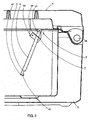
- Support arm assembly 1 has two main parts. First, it has a bracket 5 for connection to the safe's base 4. Second, it has a linear support arm 6 that connects between bracket 5 and lid 3.
- bracket 5 has a generally "L" shaped cross-section with a side face 5A adapted for placement adjacent to (and for connection to) the inner side 4A of a safe's base 4 proximate its upper edge 4B.
- the upward facing side 5B of the "L" shaped bracket is provided with an opening in the form of a linear slot 7 that is parallel to inner side 4A when bracket 5 is mounted.
- Linear support arm 6 has a generally flat planar configuration that is adapted for placement through linear slot 7 in bracket 5. When in place, support arm 6 is transverse to the upward facing side 5B of bracket 5. Support arm 6, when properly placed, is slidable in slot 7 parallel to side face 5A of bracket 5. Support arm 6 is provided with a lid connection member (denoted generally by arrow 8) pivotally connected at its upper end 6A. Lid connection member 8 is adapted to pivotally connect the upper end 6A of linear support arm 6 to safe lid 3.
- the lower end 6B of linear support arm 6 has a generally perpendicular section 6C that is bent inward and prevents support arm 6 from being withdrawn from slot 7 once our invention is assembled to a safe.
- Section 6C also allows linear support arm 6 to be quickly and easily assembled to bracket 5. This can be done by sliding section 6C through the slot 7 after bracket 5 is fastened to the side of safe body 4 and then fastening connection member 8 to safe lid 3. It can also be done by sliding section 6C through slot 7 of bracket 5 before fastening bracket 5 to the side of the safe either before or after fastening connection member 8 to safe lid 3. After this, the bracket and, if not previously fastened, the connection member 8 can be fastened in appropriate position.
- the lower end 6B also has a catch in the form of an abrupt edged notch 9 adjacent section 6C in the lower edge of linear support arm 6.
- Notch 9 is adapted to interlock with slot 7 by dropping into slot 7 (by gravity) when lid 3 is opened.
- This method for bracing lid 3 also allows lid 3 to be lowered by merely moving linear support arm 6 forward slightly towards the front of safe 2. When this is done, notch 9 no longer catches on, and interlocks with, the edge of slot 7. Lid 3 can, therefore, be allowed to drop into closed position on safe body 4.
Landscapes
- Engineering & Computer Science (AREA)
- Mechanical Engineering (AREA)
- Closures For Containers (AREA)
- Underground Structures, Protecting, Testing And Restoring Foundations (AREA)
- Building Environments (AREA)
Applications Claiming Priority (2)
| Application Number | Priority Date | Filing Date | Title |
|---|---|---|---|
| US10/305,309 US6932396B2 (en) | 2002-11-26 | 2002-11-26 | Support arm assembly for a safe lid |
| US305309 | 2002-11-28 |
Publications (1)
| Publication Number | Publication Date |
|---|---|
| EP1424462A2 true EP1424462A2 (fr) | 2004-06-02 |
Family
ID=32298050
Family Applications (1)
| Application Number | Title | Priority Date | Filing Date |
|---|---|---|---|
| EP20030026878 Withdrawn EP1424462A2 (fr) | 2002-11-26 | 2003-11-24 | Bras de support pour un couvercle de coffre-fort |
Country Status (7)
| Country | Link |
|---|---|
| US (1) | US6932396B2 (fr) |
| EP (1) | EP1424462A2 (fr) |
| JP (1) | JP2004176539A (fr) |
| CN (1) | CN1542253A (fr) |
| CA (1) | CA2450612A1 (fr) |
| MX (1) | MXPA03010784A (fr) |
| TW (1) | TW200416338A (fr) |
Families Citing this family (9)
| Publication number | Priority date | Publication date | Assignee | Title |
|---|---|---|---|---|
| US20060032860A1 (en) * | 2004-08-13 | 2006-02-16 | Hase Gary M | Container with lid prop and/or lid latch |
| KR100956997B1 (ko) * | 2007-11-28 | 2010-05-11 | 볼보 컨스트럭션 이키프먼트 홀딩 스웨덴 에이비 | 건설장비 엔진룸 후드 스테이 장치 |
| US7987939B2 (en) * | 2008-12-04 | 2011-08-02 | Honda Motor Co., Ltd. | Hood system with multiple open positions |
| US8875939B2 (en) * | 2012-12-10 | 2014-11-04 | Suncast Technologies, Llc | Storage device with hinged lid |
| CN103899169B (zh) * | 2012-12-29 | 2016-06-01 | 鸿富锦精密工业(武汉)有限公司 | 门窗悬停结构 |
| US10638657B2 (en) | 2013-01-09 | 2020-05-05 | Cnh Industrial America Llc | Lid prop system for an agricultural implement tank |
| US10711646B2 (en) | 2018-07-03 | 2020-07-14 | Rohr, Inc. | Catch assembly for controlling opening of a door |
| CN109750938B (zh) * | 2019-01-29 | 2024-04-16 | 天津现代职业技术学院 | 一种财务管理系统 |
| CN111946176B (zh) * | 2020-09-15 | 2025-05-02 | 华能伊春热电有限公司 | 运煤火车车门支撑装置 |
Family Cites Families (24)
| Publication number | Priority date | Publication date | Assignee | Title |
|---|---|---|---|---|
| US1303441A (en) | 1919-05-13 | sheets | ||
| US406595A (en) | 1889-07-09 | Trunk stay or brace | ||
| US866158A (en) * | 1907-05-31 | 1907-09-17 | John J Mcintyre | Cabinet. |
| US1096964A (en) | 1913-10-17 | 1914-05-19 | Frank C Temple | Trunk-cover holder. |
| US1335626A (en) * | 1919-07-24 | 1920-03-30 | William E Villinger | Automatic stay-arm |
| US1520907A (en) * | 1921-02-26 | 1924-12-30 | Frank G Marbach | Metal chest |
| US1986307A (en) | 1933-04-26 | 1935-01-01 | Robert E Wagner | Holding means for pivotally connected parts |
| US2587200A (en) | 1947-06-16 | 1952-02-26 | Phillips Tutch Latch Company | Hinge latch |
| US3225857A (en) * | 1963-10-01 | 1965-12-28 | Gen Motors Corp | Safety hinge and latch for a removable vehicle body closure |
| US3959859A (en) * | 1974-09-23 | 1976-06-01 | Batesville Casket Company | Casket cap brace |
| US4124240A (en) * | 1976-09-01 | 1978-11-07 | Roy Adelberg | Auto trunk lid holder |
| JPS5965183A (ja) * | 1982-10-06 | 1984-04-13 | 日産自動車株式会社 | 開閉体用サポ−トロツドの係着構造 |
| US4524496A (en) * | 1982-12-13 | 1985-06-25 | Boyertown Casket Company | Casket stay mechanism |
| US4925223A (en) * | 1989-04-13 | 1990-05-15 | Batesville Casket Company, Inc. | Cap brace for hardwood caskets |
| US5069358A (en) * | 1991-01-03 | 1991-12-03 | John D. Brush & Co., Inc. | Media case |
| US5215074A (en) * | 1992-05-29 | 1993-06-01 | General Electric Company | Lift-up cooktop locator with combined function as support rod race |
| US5570493A (en) * | 1994-11-18 | 1996-11-05 | Batesville Casket Company, Inc. | Cap brace and bracket |
| US5791428A (en) * | 1995-10-03 | 1998-08-11 | Navistar International Transportation Corp. | Locking reduced-effort hood control apparatus |
| US5765268A (en) * | 1997-03-28 | 1998-06-16 | Casket Shells, Incorporated | Casket lid support |
| US6292978B1 (en) | 1999-01-14 | 2001-09-25 | Hoffman Enclosures, Inc. | Door stop apparatus |
| JP2001055170A (ja) * | 1999-08-18 | 2001-02-27 | Honda Motor Co Ltd | 車両用ボンネット構造 |
| WO2001096169A2 (fr) * | 2000-06-14 | 2001-12-20 | Dofasco Inc. | Element de support de capot de vehicule |
| US6347818B1 (en) * | 2000-07-31 | 2002-02-19 | The Bilco Company | Hold open arm assembly |
| US6401994B1 (en) * | 2001-08-31 | 2002-06-11 | Joel R. Ham | Contra-keeper |
-
2002
- 2002-11-26 US US10/305,309 patent/US6932396B2/en not_active Expired - Fee Related
-
2003
- 2003-11-24 CA CA 2450612 patent/CA2450612A1/fr not_active Abandoned
- 2003-11-24 TW TW92132961A patent/TW200416338A/zh unknown
- 2003-11-24 EP EP20030026878 patent/EP1424462A2/fr not_active Withdrawn
- 2003-11-25 MX MXPA03010784A patent/MXPA03010784A/es unknown
- 2003-11-26 CN CNA2003101207275A patent/CN1542253A/zh active Pending
- 2003-11-26 JP JP2003395427A patent/JP2004176539A/ja active Pending
Also Published As
| Publication number | Publication date |
|---|---|
| US20040100107A1 (en) | 2004-05-27 |
| TW200416338A (en) | 2004-09-01 |
| CN1542253A (zh) | 2004-11-03 |
| CA2450612A1 (fr) | 2004-05-26 |
| US6932396B2 (en) | 2005-08-23 |
| JP2004176539A (ja) | 2004-06-24 |
| MXPA03010784A (es) | 2005-04-19 |
Similar Documents
| Publication | Publication Date | Title |
|---|---|---|
| WO2019192463A1 (fr) | Boîte de stockage assemblée | |
| US20200260897A1 (en) | Package Receptacle and Theft Deterrent Device and System | |
| US6932396B2 (en) | Support arm assembly for a safe lid | |
| US20070261207A1 (en) | Hinge attachable door stop insert | |
| KR20090002763A (ko) | 박스형 접이식 안전펜스 | |
| US12063909B2 (en) | Removable clip for an animal enclosure | |
| US4556187A (en) | Battery box hold-down | |
| WO2015085356A1 (fr) | Coffre-fort | |
| US9622575B2 (en) | Storage cabinet having a locking bar and method for securing the same | |
| US20190360240A1 (en) | Hasp with Cylindrical Lock | |
| US6829917B2 (en) | Gravity-sensitive locking assembly and weapon container | |
| US20090159597A1 (en) | Storage Device | |
| JP6933418B1 (ja) | 荷物受入装置、荷物の受け入れ取り出し方法及び荷物の受け入れ方法 | |
| KR101031806B1 (ko) | 물품보관함 잠금장치 | |
| CN209031458U (zh) | 一种加固的折叠柜装置 | |
| JP3093198U (ja) | 折り畳みボックス | |
| KR102103078B1 (ko) | 이동이 용이한 조립식 진지 | |
| CN219949126U (zh) | 一种采用隐藏卡扣结构的精品盒 | |
| JP3023965U (ja) | 下駄箱 | |
| CN222486615U (zh) | 一种折叠衣柜 | |
| JPS6320769Y2 (fr) | ||
| JPH0531958Y2 (fr) | ||
| JP3118959U (ja) | 箱位牌 | |
| JPS5832680Y2 (ja) | 貴重品ケ−ス | |
| JPH046719Y2 (fr) |
Legal Events
| Date | Code | Title | Description |
|---|---|---|---|
| PUAI | Public reference made under article 153(3) epc to a published international application that has entered the european phase |
Free format text: ORIGINAL CODE: 0009012 |
|
| AK | Designated contracting states |
Kind code of ref document: A2 Designated state(s): AT BE BG CH CY CZ DE DK EE ES FI FR GB GR HU IE IT LI LU MC NL PT RO SE SI SK TR |
|
| AX | Request for extension of the european patent |
Extension state: AL LT LV MK |
|
| STAA | Information on the status of an ep patent application or granted ep patent |
Free format text: STATUS: THE APPLICATION IS DEEMED TO BE WITHDRAWN |
|
| 18D | Application deemed to be withdrawn |
Effective date: 20070601 |