EP1424487A2 - Carburateur à balayage stratifié - Google Patents
Carburateur à balayage stratifié Download PDFInfo
- Publication number
- EP1424487A2 EP1424487A2 EP03027406A EP03027406A EP1424487A2 EP 1424487 A2 EP1424487 A2 EP 1424487A2 EP 03027406 A EP03027406 A EP 03027406A EP 03027406 A EP03027406 A EP 03027406A EP 1424487 A2 EP1424487 A2 EP 1424487A2
- Authority
- EP
- European Patent Office
- Prior art keywords
- valve
- lever
- air
- throttle valve
- choke
- Prior art date
- Legal status (The legal status is an assumption and is not a legal conclusion. Google has not performed a legal analysis and makes no representation as to the accuracy of the status listed.)
- Withdrawn
Links
- 230000002000 scavenging effect Effects 0.000 title claims abstract description 40
- 239000000446 fuel Substances 0.000 claims abstract description 41
- 239000000203 mixture Substances 0.000 claims abstract description 25
- 230000008878 coupling Effects 0.000 claims abstract description 9
- 238000010168 coupling process Methods 0.000 claims abstract description 9
- 238000005859 coupling reaction Methods 0.000 claims abstract description 9
- 239000012530 fluid Substances 0.000 claims description 11
- 238000006073 displacement reaction Methods 0.000 claims 1
- 238000007865 diluting Methods 0.000 abstract 1
- 238000010792 warming Methods 0.000 description 8
- 238000002485 combustion reaction Methods 0.000 description 3
- 230000001154 acute effect Effects 0.000 description 2
- 230000010349 pulsation Effects 0.000 description 2
- 238000010586 diagram Methods 0.000 description 1
- 239000002828 fuel tank Substances 0.000 description 1
- 230000003993 interaction Effects 0.000 description 1
- 238000004519 manufacturing process Methods 0.000 description 1
- 230000013011 mating Effects 0.000 description 1
Images


Classifications
-
- F—MECHANICAL ENGINEERING; LIGHTING; HEATING; WEAPONS; BLASTING
- F02—COMBUSTION ENGINES; HOT-GAS OR COMBUSTION-PRODUCT ENGINE PLANTS
- F02M—SUPPLYING COMBUSTION ENGINES IN GENERAL WITH COMBUSTIBLE MIXTURES OR CONSTITUENTS THEREOF
- F02M1/00—Carburettors with means for facilitating engine's starting or its idling below operational temperatures
- F02M1/02—Carburettors with means for facilitating engine's starting or its idling below operational temperatures the means to facilitate starting or idling being chokes for enriching fuel-air mixture
-
- F—MECHANICAL ENGINEERING; LIGHTING; HEATING; WEAPONS; BLASTING
- F02—COMBUSTION ENGINES; HOT-GAS OR COMBUSTION-PRODUCT ENGINE PLANTS
- F02M—SUPPLYING COMBUSTION ENGINES IN GENERAL WITH COMBUSTIBLE MIXTURES OR CONSTITUENTS THEREOF
- F02M23/00—Apparatus for adding secondary air to fuel-air mixture
- F02M23/02—Apparatus for adding secondary air to fuel-air mixture with personal control, or with secondary-air valve controlled by main combustion-air throttle
- F02M23/03—Apparatus for adding secondary air to fuel-air mixture with personal control, or with secondary-air valve controlled by main combustion-air throttle the secondary air-valve controlled by main combustion-air throttle
-
- F—MECHANICAL ENGINEERING; LIGHTING; HEATING; WEAPONS; BLASTING
- F02—COMBUSTION ENGINES; HOT-GAS OR COMBUSTION-PRODUCT ENGINE PLANTS
- F02M—SUPPLYING COMBUSTION ENGINES IN GENERAL WITH COMBUSTIBLE MIXTURES OR CONSTITUENTS THEREOF
- F02M7/00—Carburettors with means for influencing, e.g. enriching or keeping constant, fuel/air ratio of charge under varying conditions
- F02M7/12—Other installations, with moving parts, for influencing fuel/air ratio, e.g. having valves
-
- F—MECHANICAL ENGINEERING; LIGHTING; HEATING; WEAPONS; BLASTING
- F02—COMBUSTION ENGINES; HOT-GAS OR COMBUSTION-PRODUCT ENGINE PLANTS
- F02B—INTERNAL-COMBUSTION PISTON ENGINES; COMBUSTION ENGINES IN GENERAL
- F02B75/00—Other engines
- F02B75/02—Engines characterised by their cycles, e.g. six-stroke
- F02B2075/022—Engines characterised by their cycles, e.g. six-stroke having less than six strokes per cycle
- F02B2075/025—Engines characterised by their cycles, e.g. six-stroke having less than six strokes per cycle two
-
- F—MECHANICAL ENGINEERING; LIGHTING; HEATING; WEAPONS; BLASTING
- F02—COMBUSTION ENGINES; HOT-GAS OR COMBUSTION-PRODUCT ENGINE PLANTS
- F02B—INTERNAL-COMBUSTION PISTON ENGINES; COMBUSTION ENGINES IN GENERAL
- F02B25/00—Engines characterised by using fresh charge for scavenging cylinders
- F02B25/20—Means for reducing the mixing of charge and combustion residues or for preventing escape of fresh charge through outlet ports not provided for in, or of interest apart from, subgroups F02B25/02 - F02B25/18
- F02B25/22—Means for reducing the mixing of charge and combustion residues or for preventing escape of fresh charge through outlet ports not provided for in, or of interest apart from, subgroups F02B25/02 - F02B25/18 by forming air cushion between charge and combustion residues
-
- F—MECHANICAL ENGINEERING; LIGHTING; HEATING; WEAPONS; BLASTING
- F02—COMBUSTION ENGINES; HOT-GAS OR COMBUSTION-PRODUCT ENGINE PLANTS
- F02D—CONTROLLING COMBUSTION ENGINES
- F02D9/00—Controlling engines by throttling air or fuel-and-air induction conduits or exhaust conduits
- F02D9/02—Controlling engines by throttling air or fuel-and-air induction conduits or exhaust conduits concerning induction conduits
- F02D2009/0201—Arrangements; Control features; Details thereof
- F02D2009/0279—Throttle valve control for intake system with two parallel air flow paths, each controlled by a throttle, e.g. a resilient flap disposed on a throttle
-
- Y—GENERAL TAGGING OF NEW TECHNOLOGICAL DEVELOPMENTS; GENERAL TAGGING OF CROSS-SECTIONAL TECHNOLOGIES SPANNING OVER SEVERAL SECTIONS OF THE IPC; TECHNICAL SUBJECTS COVERED BY FORMER USPC CROSS-REFERENCE ART COLLECTIONS [XRACs] AND DIGESTS
- Y02—TECHNOLOGIES OR APPLICATIONS FOR MITIGATION OR ADAPTATION AGAINST CLIMATE CHANGE
- Y02T—CLIMATE CHANGE MITIGATION TECHNOLOGIES RELATED TO TRANSPORTATION
- Y02T10/00—Road transport of goods or passengers
- Y02T10/10—Internal combustion engine [ICE] based vehicles
- Y02T10/12—Improving ICE efficiencies
-
- Y—GENERAL TAGGING OF NEW TECHNOLOGICAL DEVELOPMENTS; GENERAL TAGGING OF CROSS-SECTIONAL TECHNOLOGIES SPANNING OVER SEVERAL SECTIONS OF THE IPC; TECHNICAL SUBJECTS COVERED BY FORMER USPC CROSS-REFERENCE ART COLLECTIONS [XRACs] AND DIGESTS
- Y10—TECHNICAL SUBJECTS COVERED BY FORMER USPC
- Y10S—TECHNICAL SUBJECTS COVERED BY FORMER USPC CROSS-REFERENCE ART COLLECTIONS [XRACs] AND DIGESTS
- Y10S261/00—Gas and liquid contact apparatus
- Y10S261/01—Auxiliary air inlet carburetors
Definitions
- the present invention relates generally to a carburetor and more particularly to a stratified scavenging carburetor for controlling delivery of a fuel and air mixture and scavenging air to a stratified scavenging 2-stroke engine.
- stratified scavenging arrangements have been used to reduce or prevent the blow-through or loss of fuel through exhaust ports at the time of a fuel and air mixture entering the combustion chamber.
- Some such arrangements use an air passage that is separate from a fuel and air mixture passage, and scavenging is done with a layer of air provided from the air passage at the outset of scavenging, after which scavenging is done with a fuel and air mixture, and at the same time, new air is taken into a crankcase chamber.
- the fuel to air mixture ratio within a combustion chamber of the engine can become too lean with the addition of air from the air passage at idle and other low speed and low load engine operating conditions resulting in unstable engine operation under these conditions. Further, for improved starting and warming up of the engine, it can be desirable to provide a somewhat rich fuel and air mixture to the engine. Air flow through the air passage at this time can make the fuel and air mixture leaner than desired resulting in difficulty starting and warming up the engine.
- a stratified scavenging carburetor includes a choke valve and a throttle valve rotatably supported relative to an air intake passage to control fluid flow therethrough, a scavenging air passage, an air valve rotatably supported relative to the scavenging air passage to control air flow therethrough, a lock lever carried by the throttle valve and a link providing a lost motion coupling between the throttle valve and the air valve.
- the choke valve When the engine is not running, the choke valve is open, the throttle valve is in its idle position and the air valve is closed. Movement of the choke valve to its closed position engages the choke valve with and displaces the lock lever which in turn moves or opens the throttle lever from its idle position without moving the air valve from its closed position.
- the choke valve and air valve are closed and the throttle valve is opened a desired amount from its idle position to provide a richer than normal fuel and air mixture to the engine to facilitate starting and warming up the engine.
- a stratified scavenging carburetor in another presently preferred embodiment includes a choke valve and a throttle valve rotatably supported relative to an air intake passage to control fluid flow therethrough, a scavenging air passage, an air valve rotatably supported relative to the scavenging air passage to control air flow therethrough, and driven for more rotation by the throttle during a portion of the rotation of the throttle valve between its idle and wide open position. Movement of the choke valve to its closed position for a choke-assisted start of an engine engages a choke valve lever with a lever of the air valve to prevent the air valve from moving from its closed position even when acted on by the throttle valve.
- the throttle valve can be rotated to a start position moved from its idle position to provide a richer fuel and air mixture to the engine.
- the throttle valve can be rotated beyond the position where it would cause the air valve to open if the choke valve was open.
- Some objects, features and advantages of stratified scavenging carburetors as set forth herein include providing a carburetor that delivers to an engine a desired fuel and air mixture over a wide range of operating conditions from idle to wide open throttle engine operation, and starting and warming up of an engine, enables separate control of a throttle valve during a choke assisted start of an engine, automatically sets a throttle valve to a start position upon closing a choke valve, provides an enriched fuel and air mixture to an engine to facilitate starting the engine, permits automatic return of a choke valve from its closed position to its open position, provides a compact carburetor that includes a scavenging air passage, air valve, choke valve and throttle valve, prevents delivery of scavenging air to an engine during a choke assisted start of the engine, enables relative movement between the throttle valve and air valve during at least a portion of the throttle valve movement, is durable, reliable and of economic manufacture and assembly.
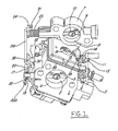
- FIG. 1 is a front perspective view of one presently preferred embodiment of a stratified scavenging carburetor
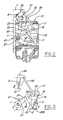
- FIG. 2 is a side view of the stratified scavenging carburetor
- FIG. 3 is a side view of certain components of the carburetor shown in a position for starting of an engine
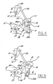
- FIG. 4 is a side view of certain components of the carburetor for explaining operation of the stratified scavenging carburetor after the engine has been started;
- FIG. 5 is a side view of certain components of the carburetor in an intermediate position
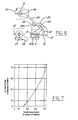
- FIG. 6 is a side view of certain components of the carburetor shown in a position corresponding to wide open throttle operation
- FIG. 7 is a diagram showing the extent to which an air valve of the stratified scavenging carburetor is open in relation to the extent to which a throttle valve is open;
- FIG. 8 is a perspective view of a second presently preferred embodiment of a carburetor illustrating an air valve shown in its closed position and a throttle valve shown in its idle position;
- FIG. 9 is another perspective view of the carburetor of FIG. 8;
- FIG. 10 is another perspective view of the carburetor of FIG. 8 showing a choke valve of the carburetor in its open position;
- FIG. 11 is a perspective view of the carburetor of FIG. 8 illustrating the air valve and throttle valve in their wide open positions;
- FIG. 12 is a perspective side view of the carburetor of FIG. 8 illustrating various levers of the carburetor when the choke valve is in its closed position, the air valve is in its closed position and the throttle valve is in its idle position;
- FIG. 13 is a perspective side view of the carburetor of FIG. 8 illustrating the levers when the choke valve is in its closed position, and the throttle valve is moved to it starting position;
- FIG. 14 is a perspective rear view of the carburetor of FIG. 8 with the choke valve and air valve in their closed positions, and the throttle valve in its starting position as in FIG. 13.
- a carburetor body 1 includes an air intake and fuel mixing passage 4 extending through the body 1 and a pump cover 15 carried by the body and securing a diaphragm 34 between the cover 15 and body 1 by a bolt 16.
- a crankcase chamber of the engine When pressure pulsations of a crankcase chamber of the engine are introduced into a pulsation pressure chamber on the upper side of the diaphragm 34 through a pipe 33, fuel in a fuel tank (not shown) is taken into a pump chamber on the lower side of the diaphragm 34 from a fuel inlet pipe 32, and is supplied to a fuel metering chamber of a substantially constant pressure fuel supply mechanism of the carburetor.
- Fuel in the fuel metering chamber is preferably supplied to the air intake passage 4 via a low-speed fuel nozzle and a high-speed fuel nozzle for delivery to the engine in a fuel and air mixture.
- fuel and air is mixed in the air intake passage which can also be called a fuel and air mixing passage.
- a butterfly-type throttle valve includes a throttle valve head 2 rotatably supported on a rear portion or outlet side of the air intake passage 4 by a throttle valve shaft 3.
- a choke valve includes a choke valve head 12 rotatably supported on the front portion or inlet side of the air intake passage 4 by a choke valve shaft 11.
- a choke valve operating lever 13 is connected to one end of the choke valve shaft 11, and a return spring 14 that yieldably biases the choke valve head 12 to an open position is wound thereon.
- One end of the return spring 14 is fastened to or abuts the carburetor body 1 and the other end of the return spring 14 is fastened to or abuts the choke valve operating lever 13.
- a throttle valve operating lever 5 is connected to one end of the throttle valve shaft 3 and a return spring 6 that yieldably biases the throttle valve 2 to an idle position is wound thereon.
- One end of the return spring 6 is fastened to or abuts the carburetor body 1 and the other end of the return spring 6 is fastened to or abuts the throttle valve operating lever 5.
- a scavenging air control body 7 for supplying scavenging air from an air cleaner (not shown) to a scavenging passage of the engine via an air passage 8 is preferably formed integral with the pump cover 15 or may be formed as part of a plate secured to and defining in part the carburetor body 1.
- the air passage 8 is preferably approximately parallel to the air intake and fuel mixing passage 4, and is provided in the scavenging air control body 7.
- An air valve 10 for opening and closing the air passage 8 to control air flow therethrough is supported by an air valve shaft 9.
- An air valve lever 24 is connected to one end of the air valve shaft 9, as shown in FIG. 1, and a return spring 25 that yieldably biases the air valve 10 toward its closed position is wound on the air valve shaft 9.
- One end of the return spring 25 is fastened to or abuts the scavenging air control body 7 and the other end of the return spring 25 is fastened to or abuts the air valve lever 24.
- a choke lever 28 is secured to one end of the choke valve shaft 11 such as by a bolt 27.
- a throttle valve lever 17 having a bent tab 19 is connected to an end of the throttle valve shaft 3, and a lock lever 20 is loosely rotatably supported on the throttle valve shaft 3.
- a spring 35 is wound on the throttle valve shaft 3 with one end 35a of the spring 35 fastened to or abutting the lock lever 20 and the other end 35b of the return spring 35 fastened to or abutting the throttle valve lever 17.
- the lock lever 20 is yieldably biased in a direction moving the lock lever away from the tab 19 by the force of the spring 35 (FIG. 1), and the tab 19 of the throttle valve lever 17 is spaced from the lock lever 20 in normal operation.
- the throttle valve lever 17 and the air valve lever 24 are connected by a link 29 that provides a lost motion coupling between the throttle valve lever 17 and the air valve lever 24.
- a link 29 that provides a lost motion coupling between the throttle valve lever 17 and the air valve lever 24.
- the air valve 10 is held in its closed position (by the force of spring 25) while the throttle valve head 2 is rotated from its idle position a predetermined amount to a start position.
- an end 30 of the link 29 is slidably received in an arcuate idler groove 18 formed in the throttle valve lever 17 and an arcuate idler groove 23 formed in the lock lever 20.
- the idler grooves 18 and 23 are generally aligned and disposed at an equal radial distance from the axis of the valve shaft 3.
- the other end of the link 29 is connected to the air valve lever 24 so as to substantially prevent lateral movement of the link 29, relative to the air valve lever 24.
- a shoulder 22 is provided which is engaged with an end of the choke lever 28 when the choke lever 28 is moved to close the choke valve head 12.
- the choke valve operating lever 13 is displaced to move the choke valve head 12 to its fully closed position. This causes the choke lever 28 to impinge upon and rotate the lock lever 20. During the rotation of the lock lever 20, it comes in contact with the tab 19 of the throttle valve lever 17, and the throttle valve lever 17 is thereby rotated to displace or open the throttle valve head 2 to a start position spaced angularly or rotated from its idle position.
- the choke lever 28 is engaged with and held on the shoulder 22.
- the air valve 10 is held in its closed position by the force of the spring 25, since the throttle valve lever 17 and lock lever 20 have not been rotated far enough to cause them to bear on and displace the link 29.
- the choke lever 28 is released from the lock lever shoulder 22, and the choke valve head 12 is moved to its fully open position by the force of the spring 14.
- the desired extent of the lost motion coupling between the throttle valve 2 and the air valve 10 can be different depending on the engine. Generally, it is desirable to permit the throttle valve to move away from idle a certain amount while maintaining the air valve 10 closed to prevent supplying too much air and hence, an undesirably lean fuel and air mixture to the engine during certain low speed and/or low power engine operating conditions. As shown in FIG.
- the air valve 10 is held at a closed position until the throttle valve head 2 is rotated about 10° to 30°, and is shown here as about 20° away from its idle position to partially open the throttle valve. With further rotation of the throttle valve, the air valve 10 opens to provide through passage 8 a scavenging air supply to the engine.
- this is accomplished by permitting the throttle valve lever 17 to move relative to the link 29 via the groove 18 for an initial portion of the opening of the throttle valve. Thereafter, as shown in FIG. 5, the end 30 of the link 29 comes in contact with the end of the idler groove 18 to begin to open the air valve 10. Desirably, the air valve 10 is fully opened as shown in FIG. 6, when the throttle valve head is in its wide open position. To accomplish this, the air valve may open more rapidly than the throttle valve.
- a stratified scavenging carburetor 50 also includes an air valve 52 rotatably supported in a scavenging air passage 54 to control air flow therethrough, and throttle and choke valves 56,58 respectively, rotatably supported within an air intake and fuel mixing passage 60 to control fluid flow therethrough.
- the throttle valve 56 includes a valve head 62 attached to a throttle valve shaft 64 for rotation with the shaft, and a throttle valve operating lever 66 at one end of the throttle valve shaft 64 which is driven to rotate the throttle valve head 62 relative to the air intake and mixing passage 60.
- the throttle valve 56 is preferably yieldably biased to its idle position by a spring 68 having one end engaged with the throttle valve operating lever 66 and its other end engaged with the carburetor body 69 or other preferably fixed surface.
- the throttle valve head 62 restricts fluid flow through the air intake passage 60.
- the throttle valve is rotatable from its idle position to a wide open throttle position wherein the throttle valve head 62 permits a substantially unrestricted fluid flow through the air intake passage 60.
- a throttle valve lever 70 is fixed on the end of the throttle valve shaft 64 opposite the throttle valve operating lever 66 for rotation with the throttle valve shaft 64.
- the throttle valve lever 70 extends at an acute included angle relative to and is preferably perpendicular to the throttle valve shaft 64 and includes a finger 72 spaced from throttle valve shaft 64 and preferably extending generally transversely to the throttle valve lever 70.
- the choke valve 58 preferably includes a choke valve head 74 attached to a choke valve shaft 76 that has a choke valve operating lever 78 at one end.
- the choke valve 58 is preferably yieldably biased to its open position preferably permitting a substantially unrestricted fluid flow therepast, by a spring 80 having one end bearing on the choke valve operating lever 78 and the other end bearing on the carburetor body 69.
- the choke valve 58 is rotatable from its open position to a closed position substantially restricting fluid flow through the air intake passage 60.
- a choke valve lever 82 is preferably carried by the choke valve shaft 76 for rotation therewith.
- the choke valve lever 82 desirably extends at an acute included angle relative to, and is preferably perpendicular to, the choke valve shaft 76 and includes a finger 84 extending therefrom and spaced from the choke valve shaft 76.
- the air valve 52 includes an air valve head 86 disposed in the air passage 54 and rotatably carried by an air valve shaft 88 extending through an end plate 90 of the carburetor body 69.
- the end plate 90 may define in part the air passage 54 as well as the air intake passage 60 and may be fastened to the carburetor main body 69 such as by screws or bolts 92.
- a U-shaped stop member 94 is preferably carried by the air valve shaft 88 for rotation therewith, and may be fastened to the air valve shaft 88 to prevent relative rotation between the stop member 94 and the air valve shaft 88.
- the stop member 94 has a pair of legs 95 joined by a crossbar 97 each with an opening (not shown) through which the air valve shaft 88 is received.
- the stop member 94 may be keyed to the air valve shaft 88 or may have a non-round opening in at least one leg 95 received on a mating non-round end of the air valve shaft 88 to prevent rotation of the stop member 94 relative to the air valve shaft 88.
- a first lever 96 is rotatably carried by the air valve shaft 88 preferably between its ends, and has a first end 98 selectively engagable with the stop member 94, and a second end 100 spaced therefrom.
- the first lever 96 preferably extends generally transversally to the axis of the air valve shaft 88 and preferably includes a hooked finger 102 adapted to engage the stop member 94.
- a screw 99 may hold the first lever 96 on the air valve shaft 88 preferably with an annular bearing 101 disposed between the first lever 96 and stop member 94.
- An air valve operating lever 104 is rotatably carried, preferably between its ends, by the air valve shaft 88.
- the air valve operating lever 104 preferably extends generally transversely to the air valve shaft 88 and has a first end 106 selectively engagable with the stop member 94 and a second end 108 spaced from the first end 106.
- the air valve operating lever 104 is preferably received between the stop member legs 95 and preferably has a hub 109 with a through bore in which the air valve shaft 88 is rotatably received.
- an adjustment screw 111 is threadedly adjustably received in the lever 104 adjacent the first end 106 and is engagable with the stop member 94.
- the air valve operating lever 104 includes a cam surface 110 disposed for engagement with the finger 72 of the throttle valve lever 70.
- the first lever 96 and air valve operating lever 104 are both yieldably biased to positions wherein their respective first ends 98, 106 engage opposite sides of the stop member 94 by a spring 112 which has one end 113 engaged with the first lever 96 and its other end 115 engaged with the air valve operating lever 104.
- the spring 112 is preferably received on the hub 109.
- the first end 98 of the first lever 96 engages one side 114 of the stop member 94 and the first end 106 of the air valve operating lever 104 engages the other side 116 of the stop member 94.
- the first ends 98, 104 of the first lever 96 and the air valve operating lever 104 are yieldably biased to rotate in opposite directions relative to the air valve shaft 88 so they rotate toward each other and into engagement with opposite sides of the stop member 94.
- the air valve 52 as a whole is yieldably biased to its closed position by a spring 118 having one end engaged with the stop member 94 and its other end engaged with the end plate 90 or carburetor body 69. In its closed position, the air valve head 86 prevents or substantially prevents air flow through the air passage 54.
- a fuel and air mixture is supplied to an engine through the air intake and mixing passage 60, and scavenging air is supplied to the engine via the scavenging air passage 54.
- the choke valve 58 is in its open position, the air valve 52 is in its closed position and the throttle valve 56 is in its idle position permitting a limited fuel and air flow through the air intake passage 60 into the engine.
- the finger 72 of the throttle valve lever 70 is spaced from the air valve operating lever 104.
- the throttle valve lever 70 is rotated and eventually its finger 72 engages and displaces the air valve actuating lever 104 to cause a corresponding movement of the air valve 52 towards its open position as shown in FIG 11.
- This lost motion coupling of the throttle valve 56 and air valve 52 permits limited movement of the throttle valve 56 without any movement of the air valve 52.
- the air valve 52 opens, the first lever 96, air valve operating lever 104 and air valve shaft 88 all rotate together with the spring 112 maintaining the first lever 96 and air valve operating lever 104 in contact with the stop member 94.
- the force of the spring 112 is preferably greater than the force required to rotate the air valve shaft 88 or the air valve operating lever 104 will separate from the stop member 94 and the opening of the air valve will be affected.
- the air valve 52 opens at a faster rate than the throttle valve 56, so that even though the throttle valve 56 begins to open sooner than the air valve 52, both the throttle valve 56 and air valve 52 reach their wide open positions at approximately the same time. This can be accomplished through, for example, appropriate design of the cam surface 110 on the air valve actuating lever 104 and its interaction with the throttle valve lever 70. Accordingly, as in the first embodiment carburetor, the throttle valve 56 is opened a predetermined distance from its idle position prior to opening the air valve 52, and thereafter, the air valve 52 opens with continued opening of the throttle valve 56.
- the choke valve 58 is moved from its open position to its closed position through movement of the choke valve operating lever 78. As best shown in FIGS. 12 and 13, this movement of the choke valve 58 causes a corresponding movement of the choke valve lever 82 and causes its finger 84 to engage and displace the first lever 96 rotatably carried by the air valve shaft 88. More specifically, the finger 84 extending from and carried by the choke valve lever 82 engages the first lever 96 and displaces it against the bias of the spring 112 so that the first end 98 is disengaged from the stop member 94. As shown in FIG.
- the throttle valve 56 can then be moved to a start position, with the throttle valve 56 moved away from its idle position a desired amount. As best shown in FIG. 13, the rotation of the throttle valve 56 to its start position can cause the throttle valve lever 70 to engage and displace the air valve actuating lever 104. However, since the first lever 96 is held against rotation by the choke valve lever 82, movement of the air valve actuating lever 104 merely rotates the first end 106 of the air valve actuating lever 104 away from the stop member 94 against the bias of the spring 112, and does not move or open the air valve 52. Hence, the throttle valve 56 can be open to a desired starting position to enrich the fuel and air mixture delivered to the engine without opening the air valve 52. This prevents air from flowing through the scavenging air passage 54 and thereby reducing the richness of the fuel and air mixture delivered to the engine. Accordingly, a richer than normal fuel and air mixture can be delivered to the engine to facilitate starting and warming it up.
- the choke valve 58 can be returned to its open position by manually rotating the choke valve lever 82, or by an automatic return of the choke valve 58 to its open position as a function of the throttle valve 56 travel towards its wide open throttle position. In one embodiment, this can be accomplished by providing the spring 112 with a spring force, when the air valve actuating lever 104 is sufficiently rotated by the throttle valve lever 70, that is greater than the force holding the choke valve 58 in its closed position. The spring force would then displace the first lever 96 so that its first end 98 moves towards the stop member 94 and releases the first lever 96 from the choke valve lever 82 so that the choke valve 58 can return to its open position via the force of the spring 80 acting on the choke valve 58.
- the choke valve 58 and throttle valve 56 could also be linked together such that movement of the throttle valve 56 passed a predetermined position towards wide open throttle moves the choke valve 58 from its closed position and thereafter permits the choke valve 58 to open thorough the force of the spring 80 acting on the choke valve 58.
- the air valve 52 opens as a function of the throttle valve opening when the throttle valve 56 is moved a predetermined distance from its idle position.
- the air valve 52 is prevented from opening by engagement of the choke valve lever 82 with the first lever 96 to prevent supplying scavenging air to the engine and thereby reducing the richness of the fuel and air mixture delivered to the engine combustion chamber. This enables a richer than normal fuel and air mixture to be delivered to the engine to facilitate starting and warming up the engine.
- the throttle valve 56 and air valve return 52 to their normal operation to provide a desired fuel and air mixture ratio to the engine throughout its range of operation from idle to wide open throttle.
Landscapes
- Engineering & Computer Science (AREA)
- Chemical & Material Sciences (AREA)
- Combustion & Propulsion (AREA)
- Mechanical Engineering (AREA)
- General Engineering & Computer Science (AREA)
- Means For Warming Up And Starting Carburetors (AREA)
- Control Of Throttle Valves Provided In The Intake System Or In The Exhaust System (AREA)
Applications Claiming Priority (2)
| Application Number | Priority Date | Filing Date | Title |
|---|---|---|---|
| JP2002344389 | 2002-11-27 | ||
| JP2002344389A JP2004176634A (ja) | 2002-11-27 | 2002-11-27 | 層状掃気用気化器 |
Publications (1)
| Publication Number | Publication Date |
|---|---|
| EP1424487A2 true EP1424487A2 (fr) | 2004-06-02 |
Family
ID=32290454
Family Applications (1)
| Application Number | Title | Priority Date | Filing Date |
|---|---|---|---|
| EP03027406A Withdrawn EP1424487A2 (fr) | 2002-11-27 | 2003-11-27 | Carburateur à balayage stratifié |
Country Status (3)
| Country | Link |
|---|---|
| US (1) | US6896245B2 (fr) |
| EP (1) | EP1424487A2 (fr) |
| JP (1) | JP2004176634A (fr) |
Cited By (10)
| Publication number | Priority date | Publication date | Assignee | Title |
|---|---|---|---|---|
| EP1559899A3 (fr) * | 2003-12-03 | 2006-07-05 | Electrolux Home Products, Inc. | Mécanisme de soupape d'air pour moteur à deux temps |
| US7144000B2 (en) | 2004-08-24 | 2006-12-05 | Briggs & Stratton Corporation | Automatic choke for an engine |
| CN101787940A (zh) * | 2009-01-22 | 2010-07-28 | 多尔玛有限公司 | 机动工具用汽化器装置 |
| CN101825043A (zh) * | 2010-05-25 | 2010-09-08 | 重庆润通动力有限公司 | 通用汽油机自动风门失效后的应急机构 |
| CN101839191A (zh) * | 2009-03-21 | 2010-09-22 | 安德烈亚斯.斯蒂尔两合公司 | 化油器装置 |
| EP1971465A4 (fr) * | 2006-01-13 | 2011-06-22 | Husqvarna Zenoah Co Ltd | Scie a chaine |
| CN102425506A (zh) * | 2011-11-16 | 2012-04-25 | 浙江中坚科技股份有限公司 | 两冲程发动机节气门与空气阀的传动连接机构 |
| US8210134B2 (en) | 2006-01-13 | 2012-07-03 | Husqvarna Zenoah Co., Ltd. | Chain saw |
| CN103867342A (zh) * | 2012-12-10 | 2014-06-18 | 陈俭敏 | 用于调整发动机转速的调速装置及具有该装置的化油器 |
| US8794196B2 (en) | 2008-10-06 | 2014-08-05 | Husqvarna Zenoah Co., Ltd. | Chain saw |
Families Citing this family (33)
| Publication number | Priority date | Publication date | Assignee | Title |
|---|---|---|---|---|
| JP2004353512A (ja) * | 2003-05-28 | 2004-12-16 | Zama Japan Kk | 2サイクルエンジン用気化器 |
| JP4061252B2 (ja) | 2003-08-11 | 2008-03-12 | ザマ・ジャパン株式会社 | 2サイクルエンジン用気化器 |
| JP4286636B2 (ja) * | 2003-11-12 | 2009-07-01 | ハスクバーナ・ゼノア株式会社 | 角度を成す弁軸間の伝導結合機構 |
| JP2005155525A (ja) * | 2003-11-27 | 2005-06-16 | Zama Japan Co Ltd | 手動チョーク機構を具えた気化器 |
| EP1766221B1 (fr) * | 2004-06-15 | 2009-11-18 | Husqvarna AB | Systeme pour moteur a deux temps a commande d'admission d'air secondaire |
| US20060043620A1 (en) * | 2004-08-24 | 2006-03-02 | David Roth | Automatic choke for an engine |
| US7429033B2 (en) * | 2004-12-10 | 2008-09-30 | Walbro Engine Management, L.L.C. | Scavenging carburetor |
| DE102004063197B4 (de) * | 2004-12-29 | 2015-05-13 | Andreas Stihl Ag & Co. Kg | Vergaseranordnung mit Starthebel und Verriegelungsvorrichtung |
| US7104253B1 (en) | 2005-03-30 | 2006-09-12 | Walbro Engine Management, L.L.C. | Stratified scavenging carburetor |
| WO2007027128A1 (fr) * | 2005-09-02 | 2007-03-08 | Husqvarna Ab | Système pour moteur à combustion évacué à carter à deux temps |
| US7325791B2 (en) * | 2005-09-15 | 2008-02-05 | Zama Japan Co., Ltd. | Carburetor for stratified scavenging two-cycle engine |
| DE102007011717B4 (de) * | 2006-03-23 | 2016-10-20 | Andreas Stihl Ag & Co. Kg | Vergaseranordnung für einen Verbrennungsmotor |
| CN101042076B (zh) * | 2006-03-23 | 2011-04-20 | 安德烈亚斯·斯蒂尔两合公司 | 内燃机的汽化装置 |
| US7380772B1 (en) * | 2006-11-01 | 2008-06-03 | Walbro Engine Management, L.L.C. | Charge forming device with controlled air bypass |
| US20080191369A1 (en) * | 2007-02-12 | 2008-08-14 | Reynolds Marion W | Carburetor Having A Rotationally Operated Choke |
| US8240639B2 (en) * | 2007-12-06 | 2012-08-14 | Briggs & Stratton Corporation | Carburetor and automatic choke assembly for an engine |
| US7854216B2 (en) * | 2008-04-25 | 2010-12-21 | Honda Motor Co., Ltd. | General purpose internal combustion engine |
| DE102009014362A1 (de) * | 2009-03-21 | 2010-09-23 | Andreas Stihl Ag & Co. Kg | Vergaser für einen Verbrennungsmotor |
| CN101881239B (zh) * | 2010-06-23 | 2012-03-21 | 陈其安 | 简易启动膜片式化油器 |
| CN101922381B (zh) * | 2010-07-23 | 2012-07-04 | 陈俭敏 | 一种化油器及其阻风门控制机构 |
| US8453998B2 (en) * | 2010-08-17 | 2013-06-04 | Walbro Engine Management, L.L.C. | Air scavenging carburetor |
| JP5318075B2 (ja) * | 2010-11-16 | 2013-10-16 | 富士重工業株式会社 | オートチョーク装置 |
| US20130062547A1 (en) * | 2011-09-13 | 2013-03-14 | Walbro Engine Management, L.L.C. | Air valve sealing plug |
| CN102444502A (zh) * | 2011-12-31 | 2012-05-09 | 福鼎市佳磐通用部件有限公司 | 通用机化油器节气门控制装置 |
| US9217410B2 (en) * | 2012-12-26 | 2015-12-22 | Generac Power Systems, Inc. | Single point engine control interface |
| US9429109B2 (en) | 2013-07-04 | 2016-08-30 | Husqvarna Ab | Carburetor assembly |
| US9464588B2 (en) | 2013-08-15 | 2016-10-11 | Kohler Co. | Systems and methods for electronically controlling fuel-to-air ratio for an internal combustion engine |
| US10054081B2 (en) | 2014-10-17 | 2018-08-21 | Kohler Co. | Automatic starting system |
| US9915221B2 (en) * | 2015-11-25 | 2018-03-13 | GM Global Technology Operations LLC | System and method for engine combustion |
| CN106988931B (zh) * | 2017-05-19 | 2023-01-06 | 威马农机股份有限公司 | 发动机化油器的阻风门和节气门联动控制机构 |
| SE541417C2 (en) * | 2017-06-12 | 2019-09-24 | Husqvarna Ab | A carburetor assembly start setting detection arrangement |
| US11543040B2 (en) | 2019-01-14 | 2023-01-03 | Illinois Tool Works Inc. | Valve |
| US11236836B2 (en) | 2019-01-14 | 2022-02-01 | Illinois Tool Works Inc. | Actuating mechanism for actuating valves |
Family Cites Families (36)
| Publication number | Priority date | Publication date | Assignee | Title |
|---|---|---|---|---|
| DE342274C (de) | 1916-12-01 | 1921-10-15 | Wilhelm Kieffer | Einrichtung zum Nachvergasen von Vergaser-Brennstoffluftgemischen |
| DE432953C (de) | 1924-02-01 | 1926-08-18 | Stromberg Motor Devices Compan | Drosselanordnung fuer Spritzvergaser |
| US2325010A (en) | 1941-06-14 | 1943-07-20 | William E Abbas | Carburetor |
| US2941788A (en) * | 1957-11-18 | 1960-06-21 | Gen Motors Corp | Four barrel carburetor |
| US3174469A (en) | 1960-04-09 | 1965-03-23 | Cvjetko Galic | Carburetor arrangement |
| FR1505407A (fr) | 1966-08-02 | 1967-12-15 | Zenith Carburateur Soc Du | Dispositif de carburation pour l'alimentation des moteurs à combustion interne |
| DE2204192C3 (de) | 1972-01-29 | 1979-03-22 | Robert Bosch Gmbh, 7000 Stuttgart | Vorrichtung zur Verbesserung der Abgase einer Vergaser-Brennkraftmaschine |
| JPS5224603B2 (fr) * | 1973-11-07 | 1977-07-02 | Honda Motor Co Ltd | |
| JPS5154133A (en) | 1974-11-06 | 1976-05-13 | Honda Motor Co Ltd | Kikakino chookubenseigyosochi |
| US4182295A (en) | 1975-07-01 | 1980-01-08 | Robert Bosch Gmbh | Method and apparatus for engine fuel control |
| JPS526835A (en) * | 1975-07-04 | 1977-01-19 | Hitachi Ltd | Assembly of carburetor |
| JPS5266119A (en) | 1975-11-28 | 1977-06-01 | Hitachi Ltd | Duplex carburetor |
| US4073278A (en) | 1976-01-16 | 1978-02-14 | Glenn Edward R | Carburator |
| DD135833B1 (de) | 1978-04-19 | 1980-07-23 | Morgenstern Carl Hans | Verfahren und vorrichtung fuer eine ladungsschichtung bei zweitakt-ottomotoren |
| JPS54140016A (en) | 1978-04-21 | 1979-10-30 | Toyota Motor Corp | Suction device of multicylinder internal combusion engine |
| US4333429A (en) | 1978-06-15 | 1982-06-08 | Honda Giken Kogyo Kabushiki Kaisha | Internal combustion engine |
| JPS5510014A (en) | 1978-07-06 | 1980-01-24 | Toyota Motor Corp | Division-operation controlled multi-cylinder internal combustion engine |
| JPS57183520A (en) | 1981-05-06 | 1982-11-11 | Isao Oda | Device for preventing mixture from blowing through two-cycle engine |
| GB2100797B (en) * | 1981-06-24 | 1985-10-09 | Suzuki Motor Co | Duplex carburetor and intake system for internal combustion engines |
| JPS5874860A (ja) * | 1981-10-30 | 1983-05-06 | Toyota Motor Corp | 内燃機関の気化器 |
| JPS58101238A (ja) * | 1981-12-11 | 1983-06-16 | Mazda Motor Corp | 過給機付エンジンの吸気装置 |
| AT394755B (de) | 1986-07-08 | 1992-06-25 | Bombardier Rotax Gmbh | Zweitakt-brennkraftmaschine mit einer kurbelkastenspuelung |
| US4796579A (en) | 1988-03-02 | 1989-01-10 | Ford Motor Company | Automotive type throttle body |
| JP2791078B2 (ja) * | 1989-02-02 | 1998-08-27 | 三信工業株式会社 | 多連装の吸気系の弁連動装置 |
| JPH02221667A (ja) * | 1989-02-23 | 1990-09-04 | Sanshin Ind Co Ltd | 多連装気化器の連動装置 |
| DE3909570A1 (de) | 1989-03-23 | 1990-09-27 | Vdo Schindling | Lastverstelleinrichtung |
| DE4117554B4 (de) | 1991-05-29 | 2004-05-27 | Walbro Gmbh | Vergaser für eine Brennkraftmaschine, insbesondere einer Motorsäge |
| IT1272718B (it) | 1993-10-01 | 1997-06-26 | Piaggio Veicoli Europ | Dispositivo di preparazione della miscela per motori a doppia alimentazione |
| US5611312A (en) | 1995-02-07 | 1997-03-18 | Walbro Corporation | Carburetor and method and apparatus for controlling air/fuel ratio of same |
| JP3768590B2 (ja) | 1996-04-03 | 2006-04-19 | 小松ゼノア株式会社 | 2行程内燃機関用気化器 |
| JP3024072B2 (ja) | 1996-10-17 | 2000-03-21 | 財団法人石油産業活性化センター | 層状掃気2サイクルエンジン |
| US6000683A (en) | 1997-11-26 | 1999-12-14 | Walbro Corporation | Carburetor throttle and choke control mechanism |
| US6202989B1 (en) | 1999-02-18 | 2001-03-20 | Walbro Corporation | Carburetor throttle and choke control mechanism |
| DE19918719B4 (de) * | 1999-04-24 | 2010-04-08 | Andreas Stihl Ag & Co. | Membranvergaser für einen mit Schichtspülung arbeitenden Zweitaktmotor |
| US6439547B1 (en) | 2001-03-05 | 2002-08-27 | Walbro Corporation | Carburetor throttle and choke control mechanism |
| US6708958B1 (en) * | 2002-10-04 | 2004-03-23 | Electrolux Home Products, Inc. | Air valve mechanism for two-cycle engine |
-
2002
- 2002-11-27 JP JP2002344389A patent/JP2004176634A/ja active Pending
-
2003
- 2003-11-21 US US10/719,519 patent/US6896245B2/en not_active Expired - Lifetime
- 2003-11-27 EP EP03027406A patent/EP1424487A2/fr not_active Withdrawn
Cited By (12)
| Publication number | Priority date | Publication date | Assignee | Title |
|---|---|---|---|---|
| EP1559899A3 (fr) * | 2003-12-03 | 2006-07-05 | Electrolux Home Products, Inc. | Mécanisme de soupape d'air pour moteur à deux temps |
| US7144000B2 (en) | 2004-08-24 | 2006-12-05 | Briggs & Stratton Corporation | Automatic choke for an engine |
| EP1630400A3 (fr) * | 2004-08-24 | 2007-01-24 | BRIGGS & STRATTON CORPORATION | Dispositif de starter automatique pour un moteur à combustion interne |
| EP1971465A4 (fr) * | 2006-01-13 | 2011-06-22 | Husqvarna Zenoah Co Ltd | Scie a chaine |
| US8210134B2 (en) | 2006-01-13 | 2012-07-03 | Husqvarna Zenoah Co., Ltd. | Chain saw |
| US8794196B2 (en) | 2008-10-06 | 2014-08-05 | Husqvarna Zenoah Co., Ltd. | Chain saw |
| CN101787940A (zh) * | 2009-01-22 | 2010-07-28 | 多尔玛有限公司 | 机动工具用汽化器装置 |
| CN101839191A (zh) * | 2009-03-21 | 2010-09-22 | 安德烈亚斯.斯蒂尔两合公司 | 化油器装置 |
| CN101839191B (zh) * | 2009-03-21 | 2014-07-23 | 安德烈亚斯.斯蒂尔两合公司 | 化油器装置 |
| CN101825043A (zh) * | 2010-05-25 | 2010-09-08 | 重庆润通动力有限公司 | 通用汽油机自动风门失效后的应急机构 |
| CN102425506A (zh) * | 2011-11-16 | 2012-04-25 | 浙江中坚科技股份有限公司 | 两冲程发动机节气门与空气阀的传动连接机构 |
| CN103867342A (zh) * | 2012-12-10 | 2014-06-18 | 陈俭敏 | 用于调整发动机转速的调速装置及具有该装置的化油器 |
Also Published As
| Publication number | Publication date |
|---|---|
| US6896245B2 (en) | 2005-05-24 |
| US20040130039A1 (en) | 2004-07-08 |
| JP2004176634A (ja) | 2004-06-24 |
Similar Documents
| Publication | Publication Date | Title |
|---|---|---|
| US6896245B2 (en) | Stratified scavenging carburetor | |
| US4196701A (en) | Internal combustion engine intake system having auxiliary passage bypassing main throttle to produce swirl in intake port | |
| US5554322A (en) | Apparatus for supplying starting-fuel for a carburetor | |
| US8122861B2 (en) | Two-stroke cycle combustion engine of air scavenging type | |
| US5250233A (en) | Carburetor with accelerator and idle circuit shut-off | |
| US6708958B1 (en) | Air valve mechanism for two-cycle engine | |
| EP1026390B1 (fr) | Carburateur pour moteur à deux temps | |
| US20050022790A1 (en) | Carburetor arrangement for an internal combustion engine | |
| US6848405B1 (en) | Self-relieving choke starting system for a combustion engine carburetor | |
| JP2000097130A (ja) | 燃料噴射式エンジン用の燃料及び空気送給装置 | |
| EP1243784A2 (fr) | Carburateur avec enrichissement en carburant | |
| JP2002155802A (ja) | プライミング機構付キャブレータ | |
| US7377496B2 (en) | Carburetor for two-cycle engine | |
| US20080258320A1 (en) | Charge forming device with idle and open throttle choke control | |
| US6679211B2 (en) | Manually guided implement | |
| JP2003049715A (ja) | 気化器のチョーク弁装置 | |
| JPH08284754A (ja) | 携帯作業装置の内燃機関用のキャブレター | |
| JP2003201918A (ja) | 手で操縦される作業機の内燃エンジンのための気化器装置 | |
| JPH04259653A (ja) | Egrバルブ防錆装置 | |
| JP2518034Y2 (ja) | ダイヤフラム式気化器 | |
| US7380772B1 (en) | Charge forming device with controlled air bypass | |
| JP2532956Y2 (ja) | ダイヤフラム式気化器を備えたエンジン | |
| JP2000018099A (ja) | 回転絞り弁式気化器 | |
| EP1559899A2 (fr) | Mécanisme de soupape d'air pour moteur à deux temps | |
| JP2003020996A (ja) | 気化器 |
Legal Events
| Date | Code | Title | Description |
|---|---|---|---|
| PUAI | Public reference made under article 153(3) epc to a published international application that has entered the european phase |
Free format text: ORIGINAL CODE: 0009012 |
|
| AK | Designated contracting states |
Kind code of ref document: A2 Designated state(s): AT BE BG CH CY CZ DE DK EE ES FI FR GB GR HU IE IT LI LU MC NL PT RO SE SI SK TR |
|
| AX | Request for extension of the european patent |
Extension state: AL LT LV MK |
|
| STAA | Information on the status of an ep patent application or granted ep patent |
Free format text: STATUS: THE APPLICATION HAS BEEN WITHDRAWN |
|
| 18W | Application withdrawn |
Effective date: 20050405 |