EP1424488A1 - Dispositif vortex pour un véhicule automobile - Google Patents
Dispositif vortex pour un véhicule automobile Download PDFInfo
- Publication number
- EP1424488A1 EP1424488A1 EP02258134A EP02258134A EP1424488A1 EP 1424488 A1 EP1424488 A1 EP 1424488A1 EP 02258134 A EP02258134 A EP 02258134A EP 02258134 A EP02258134 A EP 02258134A EP 1424488 A1 EP1424488 A1 EP 1424488A1
- Authority
- EP
- European Patent Office
- Prior art keywords
- strip
- fuel
- vehicle
- turbo
- intake
- Prior art date
- Legal status (The legal status is an assumption and is not a legal conclusion. Google has not performed a legal analysis and makes no representation as to the accuracy of the status listed.)
- Withdrawn
Links
Images


Classifications
-
- F—MECHANICAL ENGINEERING; LIGHTING; HEATING; WEAPONS; BLASTING
- F01—MACHINES OR ENGINES IN GENERAL; ENGINE PLANTS IN GENERAL; STEAM ENGINES
- F01N—GAS-FLOW SILENCERS OR EXHAUST APPARATUS FOR MACHINES OR ENGINES IN GENERAL; GAS-FLOW SILENCERS OR EXHAUST APPARATUS FOR INTERNAL-COMBUSTION ENGINES
- F01N1/00—Silencing apparatus characterised by method of silencing
- F01N1/08—Silencing apparatus characterised by method of silencing by reducing exhaust energy by throttling or whirling
- F01N1/086—Silencing apparatus characterised by method of silencing by reducing exhaust energy by throttling or whirling having means to impart a whirling motion to the exhaust gases
- F01N1/088—Silencing apparatus characterised by method of silencing by reducing exhaust energy by throttling or whirling having means to impart a whirling motion to the exhaust gases using vanes arranged on the flow path or flow tubes with tangentially directed apertures
-
- F—MECHANICAL ENGINEERING; LIGHTING; HEATING; WEAPONS; BLASTING
- F02—COMBUSTION ENGINES; HOT-GAS OR COMBUSTION-PRODUCT ENGINE PLANTS
- F02M—SUPPLYING COMBUSTION ENGINES IN GENERAL WITH COMBUSTIBLE MIXTURES OR CONSTITUENTS THEREOF
- F02M29/00—Apparatus for re-atomising condensed fuel or homogenising fuel-air mixture
- F02M29/04—Apparatus for re-atomising condensed fuel or homogenising fuel-air mixture having screens, gratings, baffles or the like
- F02M29/06—Apparatus for re-atomising condensed fuel or homogenising fuel-air mixture having screens, gratings, baffles or the like generating whirling motion of mixture
-
- F—MECHANICAL ENGINEERING; LIGHTING; HEATING; WEAPONS; BLASTING
- F02—COMBUSTION ENGINES; HOT-GAS OR COMBUSTION-PRODUCT ENGINE PLANTS
- F02B—INTERNAL-COMBUSTION PISTON ENGINES; COMBUSTION ENGINES IN GENERAL
- F02B37/00—Engines characterised by provision of pumps driven at least for part of the time by exhaust
Definitions
- the present invention relates to an insertable device for creating a vortex in a vehicle inlet or exhaust pipe, in order to enhance vehicle performance, e.g., to boost power and save fuel.
- a number of insertable devices are known that are used to provide mixing to liquid and/or gases including, inter alia, US 830 268, which is designed to improve the circulation in heating systems, US 1 345 791, US 1 584 046, and US 1 868 902.
- US 830 268 which is designed to improve the circulation in heating systems
- US 1 115 699, US 1 182 954 and US 1 396 054 that teaches that the mixing device can be formed from a single strip of cut and formed metal.
- the devices include flanges or are made from materials that have proven inferior when applied to internal combustion engines.
- Present-day large vehicles, like tractors, diesel trucks and diesel locomotive consume large amounts of fuel. Any savings in fuel will add up to a large amount of savings in operating cost over the lifetime of the vehicle.
- the inventor of the present invention has found that by designing the fuel saver device to ensure that the gas rotates through the intake or exhaust, the flow enters intake efficiently.
- the invention is directed to an insertable device in which a strip of stainless steel is cut and bent into a cylindrical shape that is capable of being inserted into a vehicle inlet or exhaust pipe and that improves the vehicle performance during normal operation of the vehicle.
- the types of vehicles which can benefit by this device include large tractors, diesel locomotives, outboard boat motors and lawnmowers, including both turbo-boosted and carburetted vehicles.
- Still another object of the invention is to provide a method of using the above device.
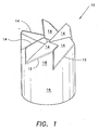
- Fig. 1 shows a fuel saver 10 according to the present invention showing its cylindrical shape.
- the structure is made from a single strip of Grade 304 or 316 stainless steel with a thickness of 25 mil for large trucks or 10 mil for other automotive vehicles.
- Tabs 18 extend from the remaining skirt 16 of the cylindrical structure 10. Each tab 18 is bent diagonally along folds 12 to produce dog-ears 14 that are oriented in an upward direction from the page.
- the starting strip of stainless steel preferably Grade 304 or 316, and preferably 10 mil or 25 mil in thickness, depending upon application, is initially cut along cut lines 20 to form square-shaped tabs 18 that extend from the skirt 16, as shown in Fig. 3.
- the strip is shaped and joined at the ends to form a cylinder, and the tabs 18 are bent radially inward in overlapping fashion to form the fuel saver 10.
- the reason for using either Grade 304 or 316 rather than carbon steel is to avoid stress fractures that may occur because of vehicle and engine vibration.
- the fuel saver 10 can be fabricated in two possible configurations: a clockwise or a counter-clockwise vortex-producing configuration.
- the fuel saver 10 For turbo-boosted vehicles, i.e., vehicles including turbo-fans in the inlet and/or the exhaust, the fuel saver 10 creates a vortex that rotates in the same direction as the direction of rotation of the nearest turbo-fan. For non-turbo-boosted vehicles, the fuel saver 10 preferably creates a clockwise vortex, when viewed in the downstream direction.
- the resulting cylindrical device is placed either inside the vehicle intake line leading to the intake manifold, upstream or downstream of the turbo fan, or inside the exhaust line in an orientation that ensures that the resulting vortex rotation produced by the gases moving through the device is the same as the rotation of the nearest turbo fan.
- the fuel saver 10 causes intake air to swirl, causing better atomization of fuel in the intake manifold, thereby providing more complete combustion of the air-fuel mixture and increased fuel economy and, in the case of turbo-assisted engines, assists the turbo fan for more power through the complete range of engine speed (i.e., rpm).
- placement of the device in the intake or fuel-injected engines placement of the device in the intake ensures improved air flow into the combustion chamber.
- the tabs are offset from the skirt by substantially 45° as this has been observed to provide a measurable increase in fuel economy across a range of engines. It has also been observed that for low-speed engines, such as diesel engines, an increased tab offset tends to provide greater fuel efficiency. Also, for highspeed engines, it has been found that a tab offset of less that 45° has been found to provide improved fuel efficiency. It will be readily apparent to those skilled in the art that the appropriate tab offset angle can be determined by trial and error, with the fuel efficiency, or power output, being monitored as different tab offset angles are used.
- Some turbo-assisted vehicles are equipped with at least two turbo fans, one placed in the inlet to the engine and another in the outlet, the two axles of the turbo fans being connected directly to each other with a shaft and, in some cases, with additional intervening gears.
- the resulting inlet-outlet turbo fans have opposite rotations. Therefore, the correct device (i.e., clockwise or counter-clockwise) to use in the inlet or outlet of these vehicles must be selected accordingly as discussed above.
- the modified vehicle may also include more than one device for greater efficiency, e.g., a device can be installed both before and after each turbo fan for a total of 4 devices.
Landscapes
- Engineering & Computer Science (AREA)
- Chemical & Material Sciences (AREA)
- Combustion & Propulsion (AREA)
- Mechanical Engineering (AREA)
- General Engineering & Computer Science (AREA)
- Exhaust Silencers (AREA)
Priority Applications (1)
| Application Number | Priority Date | Filing Date | Title |
|---|---|---|---|
| EP02258134A EP1424488A1 (fr) | 2002-11-26 | 2002-11-26 | Dispositif vortex pour un véhicule automobile |
Applications Claiming Priority (1)
| Application Number | Priority Date | Filing Date | Title |
|---|---|---|---|
| EP02258134A EP1424488A1 (fr) | 2002-11-26 | 2002-11-26 | Dispositif vortex pour un véhicule automobile |
Publications (1)
| Publication Number | Publication Date |
|---|---|
| EP1424488A1 true EP1424488A1 (fr) | 2004-06-02 |
Family
ID=32241347
Family Applications (1)
| Application Number | Title | Priority Date | Filing Date |
|---|---|---|---|
| EP02258134A Withdrawn EP1424488A1 (fr) | 2002-11-26 | 2002-11-26 | Dispositif vortex pour un véhicule automobile |
Country Status (1)
| Country | Link |
|---|---|
| EP (1) | EP1424488A1 (fr) |
Cited By (3)
| Publication number | Priority date | Publication date | Assignee | Title |
|---|---|---|---|---|
| WO2008061734A1 (fr) * | 2006-11-22 | 2008-05-29 | Emcon Technologies Germany (Augsburg) Gmbh | Élément mélangeur et système d'échappement pour un moteur à combustion interne |
| EP2098697A1 (fr) * | 2008-02-12 | 2009-09-09 | Magneti Marelli S.p.A. | Système d'échappement d'un moteur à combustion interne |
| TWI485000B (zh) * | 2013-03-11 | 2015-05-21 | Jen Sian Ind Co Ltd | Liquid mixing mechanism |
Citations (9)
| Publication number | Priority date | Publication date | Assignee | Title |
|---|---|---|---|---|
| US830268A (en) | 1905-10-27 | 1906-09-04 | Patent Fin Hot Water Heating Company | A means or device for improving the circulation and augmenting the heating capacity of the fluid in heating systems. |
| US1115699A (en) | 1912-04-30 | 1914-11-03 | Robert D Loose | Auxiliary mixer for internal-combustion engines. |
| US1182954A (en) | 1912-05-13 | 1916-05-16 | American Motors Corp | Mixing device. |
| US1345791A (en) | 1918-04-27 | 1920-07-06 | Fuel Economy Company | Gaseous mixer device |
| US1396054A (en) | 1921-01-31 | 1921-11-08 | Potter Harold Ceacle | Mixing device for internal-combustion engines |
| US1584046A (en) | 1922-10-11 | 1926-05-11 | Smith John William | Mixing device |
| US1868902A (en) | 1928-07-13 | 1932-07-26 | Thomas E Jackson | Auxiliary air intake and mixing device |
| US4515138A (en) * | 1978-06-23 | 1985-05-07 | Isaac Agadi | Internal combustion engines |
| US5113838A (en) * | 1990-06-12 | 1992-05-19 | Kim Sei Y | Air flow system for an internal combustion engine |
-
2002
- 2002-11-26 EP EP02258134A patent/EP1424488A1/fr not_active Withdrawn
Patent Citations (9)
| Publication number | Priority date | Publication date | Assignee | Title |
|---|---|---|---|---|
| US830268A (en) | 1905-10-27 | 1906-09-04 | Patent Fin Hot Water Heating Company | A means or device for improving the circulation and augmenting the heating capacity of the fluid in heating systems. |
| US1115699A (en) | 1912-04-30 | 1914-11-03 | Robert D Loose | Auxiliary mixer for internal-combustion engines. |
| US1182954A (en) | 1912-05-13 | 1916-05-16 | American Motors Corp | Mixing device. |
| US1345791A (en) | 1918-04-27 | 1920-07-06 | Fuel Economy Company | Gaseous mixer device |
| US1396054A (en) | 1921-01-31 | 1921-11-08 | Potter Harold Ceacle | Mixing device for internal-combustion engines |
| US1584046A (en) | 1922-10-11 | 1926-05-11 | Smith John William | Mixing device |
| US1868902A (en) | 1928-07-13 | 1932-07-26 | Thomas E Jackson | Auxiliary air intake and mixing device |
| US4515138A (en) * | 1978-06-23 | 1985-05-07 | Isaac Agadi | Internal combustion engines |
| US5113838A (en) * | 1990-06-12 | 1992-05-19 | Kim Sei Y | Air flow system for an internal combustion engine |
Cited By (4)
| Publication number | Priority date | Publication date | Assignee | Title |
|---|---|---|---|---|
| WO2008061734A1 (fr) * | 2006-11-22 | 2008-05-29 | Emcon Technologies Germany (Augsburg) Gmbh | Élément mélangeur et système d'échappement pour un moteur à combustion interne |
| US8607555B2 (en) | 2006-11-22 | 2013-12-17 | Faurecia Emissions Control Technologies GmbH | Mixing element and an exhaust system for an internal combustion engine |
| EP2098697A1 (fr) * | 2008-02-12 | 2009-09-09 | Magneti Marelli S.p.A. | Système d'échappement d'un moteur à combustion interne |
| TWI485000B (zh) * | 2013-03-11 | 2015-05-21 | Jen Sian Ind Co Ltd | Liquid mixing mechanism |
Similar Documents
| Publication | Publication Date | Title |
|---|---|---|
| US6837213B1 (en) | Power booster fuel saver | |
| US6536420B1 (en) | Gas swirling device for internal combustion engine | |
| US9850809B2 (en) | Inlet swirl control for turbochargers | |
| KR101771384B1 (ko) | 내연기관용 와류 발생기 | |
| EP1004767A2 (fr) | Système de recirculation de gaz d'échappement pour moteur à combustion | |
| US20120167863A1 (en) | Engine system and method with airfoil for egr introduction | |
| CA2474107C (fr) | Structure de guidage d'ecoulement pour moteur a combustion interne | |
| PT1611338E (pt) | Sistema para a melhoria do rendimento energético de um motor | |
| US4409951A (en) | Device to improve the fuel efficiency of an internal combustion engine | |
| US6889500B1 (en) | Engine exhaust extractor | |
| EP1957783B1 (fr) | Melangeur de recirculation des gaz d'echappement pour moteur a combustion interne turbocompresse | |
| KR20170123020A (ko) | 응축수 배출을 위한 엔진 시스템 | |
| US4718393A (en) | Air-fuel homogenizer | |
| WO2008032975A1 (fr) | Dispositif d'aspiration d'air pour moteur à combustion interne | |
| KR200246432Y1 (ko) | 내연기관용 흡기관의 와류 발생장치 | |
| EP1424488A1 (fr) | Dispositif vortex pour un véhicule automobile | |
| KR100757293B1 (ko) | 자동차 엔진의 출력증대장치 | |
| US20100294237A1 (en) | Air swirling device for fuel injected internal combustion engines | |
| CN202883177U (zh) | 内燃机进气系统 | |
| KR200398586Y1 (ko) | 자동차 엔진의 출력증대장치 | |
| KR20010112571A (ko) | 차량용 흡기매니폴드 | |
| US20190360358A1 (en) | Turbine outlet flow control device | |
| US20070131198A1 (en) | Device for enhancing fuel efficiency of internal combustion engines | |
| JP5262586B2 (ja) | 過給式エンジンの排気通路構造 | |
| CN2364232Y (zh) | 轮形空气旋转装置 |
Legal Events
| Date | Code | Title | Description |
|---|---|---|---|
| PUAI | Public reference made under article 153(3) epc to a published international application that has entered the european phase |
Free format text: ORIGINAL CODE: 0009012 |
|
| AK | Designated contracting states |
Kind code of ref document: A1 Designated state(s): AT BE BG CH CY CZ DE DK EE ES FI FR GB GR IE IT LI LU MC NL PT SE SK TR |
|
| AX | Request for extension of the european patent |
Extension state: AL LT LV MK RO SI |
|
| AKX | Designation fees paid | ||
| REG | Reference to a national code |
Ref country code: DE Ref legal event code: 8566 |
|
| STAA | Information on the status of an ep patent application or granted ep patent |
Free format text: STATUS: THE APPLICATION IS DEEMED TO BE WITHDRAWN |
|
| 18D | Application deemed to be withdrawn |
Effective date: 20041019 |