EP1424509A1 - Utilisation d'une transmission par engrenages dans deux variantes - Google Patents
Utilisation d'une transmission par engrenages dans deux variantes Download PDFInfo
- Publication number
- EP1424509A1 EP1424509A1 EP02102662A EP02102662A EP1424509A1 EP 1424509 A1 EP1424509 A1 EP 1424509A1 EP 02102662 A EP02102662 A EP 02102662A EP 02102662 A EP02102662 A EP 02102662A EP 1424509 A1 EP1424509 A1 EP 1424509A1
- Authority
- EP
- European Patent Office
- Prior art keywords
- gear
- gears
- transmission
- dependency
- input shaft
- Prior art date
- Legal status (The legal status is an assumption and is not a legal conclusion. Google has not performed a legal analysis and makes no representation as to the accuracy of the status listed.)
- Granted
Links
- 230000005540 biological transmission Effects 0.000 title claims description 39
- 238000002485 combustion reaction Methods 0.000 claims description 4
- 238000000034 method Methods 0.000 claims description 2
- 238000013519 translation Methods 0.000 claims description 2
- 230000014616 translation Effects 0.000 claims description 2
- 210000001520 comb Anatomy 0.000 description 3
- 230000006978 adaptation Effects 0.000 description 1
- 238000003466 welding Methods 0.000 description 1
Images
Classifications
-
- F—MECHANICAL ENGINEERING; LIGHTING; HEATING; WEAPONS; BLASTING
- F16—ENGINEERING ELEMENTS AND UNITS; GENERAL MEASURES FOR PRODUCING AND MAINTAINING EFFECTIVE FUNCTIONING OF MACHINES OR INSTALLATIONS; THERMAL INSULATION IN GENERAL
- F16H—GEARING
- F16H57/00—General details of gearing
- F16H57/02—Gearboxes; Mounting gearing therein
- F16H57/033—Series gearboxes, e.g. gearboxes based on the same design being available in different sizes or gearboxes using a combination of several standardised units
-
- F—MECHANICAL ENGINEERING; LIGHTING; HEATING; WEAPONS; BLASTING
- F16—ENGINEERING ELEMENTS AND UNITS; GENERAL MEASURES FOR PRODUCING AND MAINTAINING EFFECTIVE FUNCTIONING OF MACHINES OR INSTALLATIONS; THERMAL INSULATION IN GENERAL
- F16H—GEARING
- F16H3/00—Toothed gearings for conveying rotary motion with variable gear ratio or for reversing rotary motion
- F16H3/02—Toothed gearings for conveying rotary motion with variable gear ratio or for reversing rotary motion without gears having orbital motion
- F16H3/08—Toothed gearings for conveying rotary motion with variable gear ratio or for reversing rotary motion without gears having orbital motion exclusively or essentially with continuously meshing gears, that can be disengaged from their shafts
- F16H3/087—Toothed gearings for conveying rotary motion with variable gear ratio or for reversing rotary motion without gears having orbital motion exclusively or essentially with continuously meshing gears, that can be disengaged from their shafts characterised by the disposition of the gears
- F16H3/093—Toothed gearings for conveying rotary motion with variable gear ratio or for reversing rotary motion without gears having orbital motion exclusively or essentially with continuously meshing gears, that can be disengaged from their shafts characterised by the disposition of the gears with two or more countershafts
-
- F—MECHANICAL ENGINEERING; LIGHTING; HEATING; WEAPONS; BLASTING
- F16—ENGINEERING ELEMENTS AND UNITS; GENERAL MEASURES FOR PRODUCING AND MAINTAINING EFFECTIVE FUNCTIONING OF MACHINES OR INSTALLATIONS; THERMAL INSULATION IN GENERAL
- F16H—GEARING
- F16H3/00—Toothed gearings for conveying rotary motion with variable gear ratio or for reversing rotary motion
- F16H3/02—Toothed gearings for conveying rotary motion with variable gear ratio or for reversing rotary motion without gears having orbital motion
- F16H3/08—Toothed gearings for conveying rotary motion with variable gear ratio or for reversing rotary motion without gears having orbital motion exclusively or essentially with continuously meshing gears, that can be disengaged from their shafts
- F16H3/087—Toothed gearings for conveying rotary motion with variable gear ratio or for reversing rotary motion without gears having orbital motion exclusively or essentially with continuously meshing gears, that can be disengaged from their shafts characterised by the disposition of the gears
- F16H3/093—Toothed gearings for conveying rotary motion with variable gear ratio or for reversing rotary motion without gears having orbital motion exclusively or essentially with continuously meshing gears, that can be disengaged from their shafts characterised by the disposition of the gears with two or more countershafts
- F16H2003/0931—Toothed gearings for conveying rotary motion with variable gear ratio or for reversing rotary motion without gears having orbital motion exclusively or essentially with continuously meshing gears, that can be disengaged from their shafts characterised by the disposition of the gears with two or more countershafts each countershaft having an output gear meshing with a single common gear on the output shaft
-
- F—MECHANICAL ENGINEERING; LIGHTING; HEATING; WEAPONS; BLASTING
- F16—ENGINEERING ELEMENTS AND UNITS; GENERAL MEASURES FOR PRODUCING AND MAINTAINING EFFECTIVE FUNCTIONING OF MACHINES OR INSTALLATIONS; THERMAL INSULATION IN GENERAL
- F16H—GEARING
- F16H2200/00—Transmissions for multiple ratios
- F16H2200/003—Transmissions for multiple ratios characterised by the number of forward speeds
- F16H2200/0052—Transmissions for multiple ratios characterised by the number of forward speeds the gear ratios comprising six forward speeds
Definitions
- the invention relates to the use of a gear change transmission for Motor vehicles in at least two transmission variants according to the preamble of claim 1.
- EP 0 046 373 describes a transmission concept for a 6-speed countershaft transmission for motor vehicles according to the preamble of Claim 1 known that an input shaft and two parallel to it arranged countershafts, each provided with a pinion are in engagement with a final output gear. On the input shaft fixed gears are arranged, which are in constant engagement with idler gears Countershafts are adjacent to those single or double Synchronizing units are provided, via which they correspond with their corresponding Waves driving can be connected.
- the idler gears form 3rd and 5th gear a dependency by using the same fixed gear on the input shaft comb, and the idler gears of 4th and 6th gear form another dependency, by sharing it with another fixed gear on the input shaft comb.
- a similar 6-speed gearbox with an arrangement of the gear wheels is known from EP 1 067 312. It includes one transmission input shaft, two Intermediate shafts, a transmission output shaft and arranged thereon Whole gears and sliding sleeves.
- the idler gears for the first to fourth gear are arranged switchable on the first intermediate shaft, the idler gears for the fifth, sixth and the reverse gear are on the second intermediate shaft arranged switchable.
- the object of the invention is therefore the existing transmission concept further develop that one for different transmission variants Gear change gear different gear gradations are possible with the gearbox variants only minor design difference should have.
- the object is achieved with the features of the claim 1.
- a particularly advantageous embodiment of the invention results when a first transmission variant has a dependency between 4th and 6th gear, and a second transmission variant a dependency between 3rd and 5th gear has by the two loose wheels involved in the dependency and the Fixed gear for the first transmission variant, the translations for the 4th and 6th Gear and with the second transmission variant for the 3rd and 5th gear.
- Both transmission variants can have six forward gears, there are but also possible, the one or both transmission variants even more Have forward gears.
- These transmission variants are advantageous used in internal combustion engines in motor vehicles, the Gearbox variant with the dependency between 4th and 6th gear as a gearbox for a diesel engine, and the other transmission variant with the dependency between 3rd and 5th gear is provided as a transmission for a gasoline engine.
- the fixed gears for the upper gears are not advantageous on the input shaft with the input shaft made from one piece, but are retrofitted connected in a rotationally fixed manner to the input shaft by a suitable method.
- the Connection can be made using a suitable positive or non-positive connection such as Spline, polygonal profiles, laser welding or by shrinking or Pressing the gears onto the input shaft.
- a suitable positive or non-positive connection such as Spline, polygonal profiles, laser welding or by shrinking or Pressing the gears onto the input shaft.
- the replaced gears do not change because they, at least in part, only have new gears with different ones Receive pitch circle diameters, the basic dimensions, however Bore diameter, overall length, position and fastening on the shafts, Gear teeth etc. do not change. All other essential components of the transmission, such as shafts, housing, synchronizers are included the two transmission variants are largely identical. Only that Actuator in a manually shifted transmission must u. U. for the exchanged gears are deflected so that, for. B. the usual H-switching scheme can be maintained for the driver. However, this does not apply even if the transmission is automated and using shift actuators is switched.
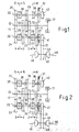
- Fig. 1 and 2 are two transmissions according to the invention, each with 6 gears schematically shown, Fig. 1 shows the transmission variant with a 4/6 Dependency and Fig. 2 shows the transmission variant with a 3/5 dependency represents.
- the input shaft 10 is via the clutch 17 with the shown engine connected. Fixed wheels 11 are on input shaft 10 to 16 for gears 1 to 6 arranged in a rigid manner.
- On the first intermediate shaft 20 are the idler gears 21 to 24 for gears 1 to 4, which over the Switching devices 28 and 29 are rotationally rigid with the first intermediate shaft 20 are switchable.
- the idler gears 35 are located on the second intermediate shaft 30 and 36 for gears 5 and 6 and idler gear 37 for reverse gear, wherein all idler gears are also rotationally rigid via the switching devices 38 and 39 are switchable with the second intermediate shaft 30.
- Fig. 1 the arrangement of the fixed wheels is seen on the engine side Input shaft 11 as follows: Fixed gear 11, which with idler gear 21 for 1st gear combs, then fixed gear 12, which meshes with idler gear 22 for the 2nd gear, then Fixed gear 15, which meshes with idler gear 35 for 5th gear, then fixed gear 13, which meshes with idler gear 23 for 3rd gear and at the end of Input shaft the fixed gear 14, both with the idler gear 24 for the 4th gear as well as with the idler gear 36 for 6th gear. From this arrangement the Fixed gears result in switching pairs of the idler gears, each over a common switching device can be switched.
- Idler gear 21 and 22 for the 1st 2nd and 2nd gear are rotationally rigid with the first via the switching device 28
- Intermediate shaft 20 can be connected, idler gear 23 and 24 for 3rd and 4th gear via the switching device 29 with the first intermediate shaft 20 connectable and idler gear 35 and 36 for 5th and 6th gear are on the Switching device 39 can be connected in a torsionally rigid manner to the second intermediate shaft 30.
- First and second intermediate shafts 20 and 30 point at the motor end output gears 41 and 42 arranged in a torsionally rigid manner, both with a Ring gear 44 of the output shaft 40, which the driving force on the Axle output shafts 46 passes to the wheels.
- Fig. 2 differs only in the arrangement of the gears upper gears from 3rd gear, all other components, especially the switching devices do not change. From the engine side, this results following arrangement: fixed gear 11, which meshes with idler gear 21 for 1st gear, then fixed gear 12, which meshes with idler gear 22 for 2nd gear, then fixed gear 16, which meshes with idler gear 36 for 6th gear, then fixed gear 14, which with combs the idler gear 24 for the 4th gear and at the end of the input shaft Fixed gear 13, both with the idler gear 23 for the 3rd gear and with the Idler gear 35 combs for 5th gear.
Landscapes
- Engineering & Computer Science (AREA)
- General Engineering & Computer Science (AREA)
- Mechanical Engineering (AREA)
- Structure Of Transmissions (AREA)
Priority Applications (2)
| Application Number | Priority Date | Filing Date | Title |
|---|---|---|---|
| DE50211792T DE50211792D1 (de) | 2002-11-28 | 2002-11-28 | Verwendung eines Zahnradgetriebes in zwei Getriebevarianten |
| EP20020102662 EP1424509B1 (fr) | 2002-11-28 | 2002-11-28 | Utilisation d'une transmission par engrenages dans deux variantes |
Applications Claiming Priority (1)
| Application Number | Priority Date | Filing Date | Title |
|---|---|---|---|
| EP20020102662 EP1424509B1 (fr) | 2002-11-28 | 2002-11-28 | Utilisation d'une transmission par engrenages dans deux variantes |
Publications (2)
| Publication Number | Publication Date |
|---|---|
| EP1424509A1 true EP1424509A1 (fr) | 2004-06-02 |
| EP1424509B1 EP1424509B1 (fr) | 2008-02-27 |
Family
ID=32241341
Family Applications (1)
| Application Number | Title | Priority Date | Filing Date |
|---|---|---|---|
| EP20020102662 Expired - Lifetime EP1424509B1 (fr) | 2002-11-28 | 2002-11-28 | Utilisation d'une transmission par engrenages dans deux variantes |
Country Status (2)
| Country | Link |
|---|---|
| EP (1) | EP1424509B1 (fr) |
| DE (1) | DE50211792D1 (fr) |
Cited By (5)
| Publication number | Priority date | Publication date | Assignee | Title |
|---|---|---|---|---|
| DE102004034217A1 (de) * | 2004-07-14 | 2006-02-09 | Zf Friedrichshafen Ag | Geteilter Stabilisator mit optimierter Federrate |
| JP2009030700A (ja) * | 2007-07-26 | 2009-02-12 | Mazda Motor Corp | 変速機 |
| EP2060827A1 (fr) | 2007-11-14 | 2009-05-20 | Getrag Ford Transmissions GmbH | Utilisation d'un engrenage à double embrayage dans deux variantes d'engrenages |
| WO2011151129A1 (fr) * | 2010-05-31 | 2011-12-08 | Siemens Aktiengesellschaft | Série de pièces de boîte de vitesses transmettant un couple |
| WO2012084631A1 (fr) | 2010-12-22 | 2012-06-28 | Getrag Ford Transmissions Gmbh | Procédé pour la modification d'une boîte de vitesses manuelle |
Citations (8)
| Publication number | Priority date | Publication date | Assignee | Title |
|---|---|---|---|---|
| GB2074669A (en) * | 1980-04-25 | 1981-11-04 | Volvo Ab | Vehicle gearbox |
| EP0046373A1 (fr) | 1980-08-14 | 1982-02-24 | Automotive Products Public Limited Company | Transmission rotative |
| GB2103316A (en) * | 1981-08-06 | 1983-02-16 | Zahnradfabrik Friedrichshafen | Layshaft change-speed gear unit with concentric input shafts drivable through double clutch |
| US5311789A (en) * | 1991-11-06 | 1994-05-17 | Getrag Getriebe-Und Zahnradfabrik H.H. Gmbh | Motor vehicle transmission having gearings for six forward speeds and one reverse speed |
| EP1067312A1 (fr) * | 1999-07-05 | 2001-01-10 | Ford Global Technologies, Inc., A subsidiary of Ford Motor Company | Transmission à six rapports pour véhicules automobiles |
| EP1245863A2 (fr) * | 2001-03-27 | 2002-10-02 | C.R.F. Società Consortile per Azioni | Boíte de vitesse de véhicule |
| EP1267312A1 (fr) | 2001-06-01 | 2002-12-18 | Ralf Hauser | Methode et systéme pour effectuer des secures transactions en-ligne |
| WO2003019043A1 (fr) * | 2001-08-22 | 2003-03-06 | Zf Friedrichshafen Ag | Transmission a deux arbres de renvoi |
-
2002
- 2002-11-28 DE DE50211792T patent/DE50211792D1/de not_active Expired - Lifetime
- 2002-11-28 EP EP20020102662 patent/EP1424509B1/fr not_active Expired - Lifetime
Patent Citations (8)
| Publication number | Priority date | Publication date | Assignee | Title |
|---|---|---|---|---|
| GB2074669A (en) * | 1980-04-25 | 1981-11-04 | Volvo Ab | Vehicle gearbox |
| EP0046373A1 (fr) | 1980-08-14 | 1982-02-24 | Automotive Products Public Limited Company | Transmission rotative |
| GB2103316A (en) * | 1981-08-06 | 1983-02-16 | Zahnradfabrik Friedrichshafen | Layshaft change-speed gear unit with concentric input shafts drivable through double clutch |
| US5311789A (en) * | 1991-11-06 | 1994-05-17 | Getrag Getriebe-Und Zahnradfabrik H.H. Gmbh | Motor vehicle transmission having gearings for six forward speeds and one reverse speed |
| EP1067312A1 (fr) * | 1999-07-05 | 2001-01-10 | Ford Global Technologies, Inc., A subsidiary of Ford Motor Company | Transmission à six rapports pour véhicules automobiles |
| EP1245863A2 (fr) * | 2001-03-27 | 2002-10-02 | C.R.F. Società Consortile per Azioni | Boíte de vitesse de véhicule |
| EP1267312A1 (fr) | 2001-06-01 | 2002-12-18 | Ralf Hauser | Methode et systéme pour effectuer des secures transactions en-ligne |
| WO2003019043A1 (fr) * | 2001-08-22 | 2003-03-06 | Zf Friedrichshafen Ag | Transmission a deux arbres de renvoi |
Cited By (10)
| Publication number | Priority date | Publication date | Assignee | Title |
|---|---|---|---|---|
| DE102004034217A1 (de) * | 2004-07-14 | 2006-02-09 | Zf Friedrichshafen Ag | Geteilter Stabilisator mit optimierter Federrate |
| US7819406B2 (en) | 2004-07-14 | 2010-10-26 | Zf Friedrichshafen Ag | Split stabilizer with optimized spring rate |
| JP2009030700A (ja) * | 2007-07-26 | 2009-02-12 | Mazda Motor Corp | 変速機 |
| EP2060827A1 (fr) | 2007-11-14 | 2009-05-20 | Getrag Ford Transmissions GmbH | Utilisation d'un engrenage à double embrayage dans deux variantes d'engrenages |
| US8307729B2 (en) | 2007-11-14 | 2012-11-13 | Getrag Ford Transmissions Gmbh | Dual clutch transmission with modifiable gear speeds and use of the transmission for at least two transmission variations |
| WO2011151129A1 (fr) * | 2010-05-31 | 2011-12-08 | Siemens Aktiengesellschaft | Série de pièces de boîte de vitesses transmettant un couple |
| WO2012084631A1 (fr) | 2010-12-22 | 2012-06-28 | Getrag Ford Transmissions Gmbh | Procédé pour la modification d'une boîte de vitesses manuelle |
| DE102010055735A1 (de) | 2010-12-22 | 2012-06-28 | Getrag Ford Transmissions Gmbh | Verfahren zur Modifizierung eines Schaltgetriebes |
| CN103380313A (zh) * | 2010-12-22 | 2013-10-30 | 格特拉克·福特传动系统有限公司 | 用于改进换挡变速器的方法 |
| CN103380313B (zh) * | 2010-12-22 | 2016-02-03 | 格特拉克·福特传动系统有限公司 | 用于改进换挡变速器的方法 |
Also Published As
| Publication number | Publication date |
|---|---|
| EP1424509B1 (fr) | 2008-02-27 |
| DE50211792D1 (de) | 2008-04-10 |
Similar Documents
| Publication | Publication Date | Title |
|---|---|---|
| EP2060827B1 (fr) | Utilisation d'un engrenage à double embrayage dans deux variantes d'engrenages | |
| EP0540989B1 (fr) | Transmission à six rapports | |
| DE102004001278B4 (de) | Doppelkupplungsgetriebe für ein Kraftfahrzeug | |
| DE3320494A1 (de) | Wechselgetriebe mit synchronisiertem rueckwaertsgang | |
| DE69518078T2 (de) | Kraftfahrzeuggetriebe | |
| DE19524233C2 (de) | Kurzbauendes Sechsganggetriebe | |
| DE4116189C2 (de) | Schaltgetriebe | |
| DE19624857B4 (de) | Kurzbauendes Sechsganggetriebe | |
| EP1740848A1 (fr) | Boite de vitesses a arbre de renvoi | |
| EP2469125B1 (fr) | Boîte de vitesses automatique, notamment automatisée, pour un véhicule automobile | |
| EP3259496A1 (fr) | Boîte de vitesses à double embrayage pour véhicule à moteur | |
| EP2655924B1 (fr) | Transmission à contournement à double embrayage | |
| EP1455116B1 (fr) | Boîte de vitesses compacte | |
| EP2739878B1 (fr) | Boîte de vitesses pour un véhicule automobile | |
| EP1443245B1 (fr) | Transmission d'un véhicule à moteur | |
| EP2655925B1 (fr) | Procédé pour la modification d'une boîte de vitesses manuelle | |
| EP1424509B1 (fr) | Utilisation d'une transmission par engrenages dans deux variantes | |
| DE102016218893B4 (de) | Doppelkupplungsgetriebe für Kraftfahrzeuge | |
| DE3236956A1 (de) | Zahnraederwechselgetriebe in gruppenbauweise | |
| EP0595059B1 (fr) | Boîte de vitesses pour véhicule automobile | |
| DE10307178B4 (de) | Kraftfahrzeuggetriebe | |
| DE102016122706B3 (de) | Schaltgetriebe mit Ölpumpe | |
| WO2009135807A1 (fr) | Boîte de vitesses ou boîte de vitesses à double embrayage manuelle ou automatique à renvoi | |
| DE102015204600B4 (de) | Getriebe für ein Kraftfahrzeug und Verfahren zum Betreiben eines solchen | |
| DE102016204856B3 (de) | Kraftfahrzeuggetriebe |
Legal Events
| Date | Code | Title | Description |
|---|---|---|---|
| PUAI | Public reference made under article 153(3) epc to a published international application that has entered the european phase |
Free format text: ORIGINAL CODE: 0009012 |
|
| AK | Designated contracting states |
Kind code of ref document: A1 Designated state(s): AT BE BG CH CY CZ DE DK EE ES FI FR GB GR IE IT LI LU MC NL PT SE SK TR |
|
| AX | Request for extension of the european patent |
Extension state: AL LT LV MK RO SI |
|
| 17P | Request for examination filed |
Effective date: 20041202 |
|
| AKX | Designation fees paid |
Designated state(s): DE FR GB |
|
| 17Q | First examination report despatched |
Effective date: 20070727 |
|
| GRAP | Despatch of communication of intention to grant a patent |
Free format text: ORIGINAL CODE: EPIDOSNIGR1 |
|
| GRAS | Grant fee paid |
Free format text: ORIGINAL CODE: EPIDOSNIGR3 |
|
| GRAA | (expected) grant |
Free format text: ORIGINAL CODE: 0009210 |
|
| AK | Designated contracting states |
Kind code of ref document: B1 Designated state(s): DE FR GB |
|
| REG | Reference to a national code |
Ref country code: GB Ref legal event code: FG4D Free format text: NOT ENGLISH |
|
| REF | Corresponds to: |
Ref document number: 50211792 Country of ref document: DE Date of ref document: 20080410 Kind code of ref document: P |
|
| ET | Fr: translation filed | ||
| PLBE | No opposition filed within time limit |
Free format text: ORIGINAL CODE: 0009261 |
|
| STAA | Information on the status of an ep patent application or granted ep patent |
Free format text: STATUS: NO OPPOSITION FILED WITHIN TIME LIMIT |
|
| 26N | No opposition filed |
Effective date: 20081128 |
|
| REG | Reference to a national code |
Ref country code: FR Ref legal event code: PLFP Year of fee payment: 14 |
|
| REG | Reference to a national code |
Ref country code: FR Ref legal event code: PLFP Year of fee payment: 15 |
|
| REG | Reference to a national code |
Ref country code: FR Ref legal event code: PLFP Year of fee payment: 16 |
|
| REG | Reference to a national code |
Ref country code: FR Ref legal event code: PLFP Year of fee payment: 17 |
|
| PGFP | Annual fee paid to national office [announced via postgrant information from national office to epo] |
Ref country code: GB Payment date: 20201029 Year of fee payment: 19 |
|
| PGFP | Annual fee paid to national office [announced via postgrant information from national office to epo] |
Ref country code: DE Payment date: 20211013 Year of fee payment: 20 |
|
| PGFP | Annual fee paid to national office [announced via postgrant information from national office to epo] |
Ref country code: FR Payment date: 20211025 Year of fee payment: 20 |
|
| GBPC | Gb: european patent ceased through non-payment of renewal fee |
Effective date: 20211128 |
|
| PG25 | Lapsed in a contracting state [announced via postgrant information from national office to epo] |
Ref country code: GB Free format text: LAPSE BECAUSE OF NON-PAYMENT OF DUE FEES Effective date: 20211128 |
|
| REG | Reference to a national code |
Ref country code: DE Ref legal event code: R071 Ref document number: 50211792 Country of ref document: DE |