EP1424763A1 - Structure de fixation de roulement - Google Patents
Structure de fixation de roulement Download PDFInfo
- Publication number
- EP1424763A1 EP1424763A1 EP02026200A EP02026200A EP1424763A1 EP 1424763 A1 EP1424763 A1 EP 1424763A1 EP 02026200 A EP02026200 A EP 02026200A EP 02026200 A EP02026200 A EP 02026200A EP 1424763 A1 EP1424763 A1 EP 1424763A1
- Authority
- EP
- European Patent Office
- Prior art keywords
- ball bearing
- adhesive
- outer periphery
- inner periphery
- fixing structure
- Prior art date
- Legal status (The legal status is an assumption and is not a legal conclusion. Google has not performed a legal analysis and makes no representation as to the accuracy of the status listed.)
- Withdrawn
Links
- 239000000853 adhesive Substances 0.000 claims abstract description 25
- 230000001070 adhesive effect Effects 0.000 claims abstract description 25
- 230000002411 adverse Effects 0.000 description 2
- 230000004048 modification Effects 0.000 description 2
- 238000012986 modification Methods 0.000 description 2
Images


Classifications
-
- F—MECHANICAL ENGINEERING; LIGHTING; HEATING; WEAPONS; BLASTING
- F16—ENGINEERING ELEMENTS AND UNITS; GENERAL MEASURES FOR PRODUCING AND MAINTAINING EFFECTIVE FUNCTIONING OF MACHINES OR INSTALLATIONS; THERMAL INSULATION IN GENERAL
- F16C—SHAFTS; FLEXIBLE SHAFTS; ELEMENTS OR CRANKSHAFT MECHANISMS; ROTARY BODIES OTHER THAN GEARING ELEMENTS; BEARINGS
- F16C35/00—Rigid support of bearing units; Housings, e.g. caps, covers
- F16C35/04—Rigid support of bearing units; Housings, e.g. caps, covers in the case of ball or roller bearings
- F16C35/06—Mounting or dismounting of ball or roller bearings; Fixing them onto shaft or in housing
-
- H—ELECTRICITY
- H02—GENERATION; CONVERSION OR DISTRIBUTION OF ELECTRIC POWER
- H02K—DYNAMO-ELECTRIC MACHINES
- H02K5/00—Casings; Enclosures; Supports
- H02K5/04—Casings or enclosures characterised by the shape, form or construction thereof
- H02K5/16—Means for supporting bearings, e.g. insulating supports or means for fitting bearings in the bearing-shields
- H02K5/173—Means for supporting bearings, e.g. insulating supports or means for fitting bearings in the bearing-shields using bearings with rolling contact, e.g. ball bearings
- H02K5/1735—Means for supporting bearings, e.g. insulating supports or means for fitting bearings in the bearing-shields using bearings with rolling contact, e.g. ball bearings radially supporting the rotary shaft at only one end of the rotor
-
- F—MECHANICAL ENGINEERING; LIGHTING; HEATING; WEAPONS; BLASTING
- F16—ENGINEERING ELEMENTS AND UNITS; GENERAL MEASURES FOR PRODUCING AND MAINTAINING EFFECTIVE FUNCTIONING OF MACHINES OR INSTALLATIONS; THERMAL INSULATION IN GENERAL
- F16C—SHAFTS; FLEXIBLE SHAFTS; ELEMENTS OR CRANKSHAFT MECHANISMS; ROTARY BODIES OTHER THAN GEARING ELEMENTS; BEARINGS
- F16C2226/00—Joining parts; Fastening; Assembling or mounting parts
- F16C2226/30—Material joints
- F16C2226/40—Material joints with adhesive
-
- F—MECHANICAL ENGINEERING; LIGHTING; HEATING; WEAPONS; BLASTING
- F16—ENGINEERING ELEMENTS AND UNITS; GENERAL MEASURES FOR PRODUCING AND MAINTAINING EFFECTIVE FUNCTIONING OF MACHINES OR INSTALLATIONS; THERMAL INSULATION IN GENERAL
- F16C—SHAFTS; FLEXIBLE SHAFTS; ELEMENTS OR CRANKSHAFT MECHANISMS; ROTARY BODIES OTHER THAN GEARING ELEMENTS; BEARINGS
- F16C2380/00—Electrical apparatus
- F16C2380/26—Dynamo-electric machines or combinations therewith, e.g. electro-motors and generators
Definitions
- the present invention relates to a ball bearing fixing structure.
- the present invention relates to a ball bearing fixing structure for bonding the inner and outer peripheries of the ball bearing by fixing sections.
- Fig. 1 of the drawings illustrates a conventional ball bearing 1 including an outer race 10, and an inner race 11, and a plurality of balls 12.
- the outer race 10 and the inner race 11 are engaged with each other with the balls 12 mounted therebetween to thereby allow smooth relative rotation between the outer race 10 and the inner race 11.
- the ball bearing 1 is mounted between, e.g., an axle tube 2 and a rotatable shaft 3 of, e.g., a rotor of a motor.
- the rotatable shaft 3 may rotate freely relative to the axle tube 2.
- an outer periphery of the ball bearing 1 is bonded by adhesive to an inner periphery of the axle tube 2, and an inner periphery of the ball bearing 1 is bonded to the outer periphery of the rotatable shaft 3.
- the fixing sections receive excessive adhesive to avoid overflow or insufficiency of the adhesive.
- the fixing sections improve the bonding strength and thus provide a reliable structure.
- a ball bearing fixing structure in accordance with the present invention includes a ball bearing having an outer periphery and an inner periphery, a first member having an inner periphery bonded by an adhesive to the outer periphery of the ball bearing, and a second member having an outer periphery bonded by the adhesive to the inner periphery of the ball bearing. At least one of the inner periphery of the first member and the outer periphery of the second member includes at least one fixing section for accumulating the adhesive.
- the fixing section may be an annular groove or a recessed portion for accumulating the adhesive and for increasing the bonding area that results in improved bonding strength.
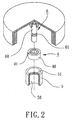
- a ball bearing fixing structure in accordance with the present invention generally includes a ball bearing 4, a first member 5, and a second member 6.
- the ball bearing 4 includes an inner periphery 40 and an outer periphery 41 for respectively engaging with the first member 5 and the second member 6, thereby allowing relative free rotation between the first member 5 and the second member 6.
- the first member 5 may be an axle tube or a stator and includes an inner periphery 50 and a first fixing section 51.
- the first fixing section 51 is located on a predetermined position and extends along the inner periphery 50 of the first member 5.
- the second member 6 may be a rotatable shaft of a rotor and includes an outer periphery 60 and a second fixing section 61.
- the second fixing section 61 is located on a predetermined position and extends along the outer periphery 60 of the second member 6.
- the first and second fixing sections 51 and 61 are preferably annular grooves for accumulating adhesive. Alternatively, the first and second fixing sections 51 and 61 are recessed portions for accumulating adhesive.
- the ball bearing 4 in assembly, is mounted between the first member 5 and the second member 6 with the first fixing section 51 facing the outer periphery 41 of the ball bearing 4 and with the second fixing section 62 facing the inner periphery 40 of the ball bearing 4.
- the outer periphery 41 of the ball bearing 4 is bonded by an adhesive to the first fixing section 51 of the first member 5, and the inner periphery 40 of the ball bearing 4 is bonded by adhesive to the second fixing section 61 of the second member 6.
- the adhesive on the outer periphery 41 of the ball bearing 4 is accumulated in the first fixing section 51 of the first member 5 to thereby improve the bonding strength.
- the adhesive on the inner periphery 40 of the ball bearing 4 is accumulated in the second fixing section 61 of the second member 6 to thereby increase the bonding area that results in improved bonding strength.
- the adhesive on the outer periphery 41 and the adhesive on the inner periphery 40 of the ball bearing 4 may withstand high-speed rotation of the second member 6 relative to the first member 5.
- the ball bearing 4 may be used with high-speed rotation of motors.
- the conventional ball bearing 1 risks the contaminated zones "a" on two ends thereof resulting from overflow of adhesive, which would adversely affect smooth rotation of the ball bearing 1 and generate rotational noise, while overflow of adhesive is avoided and the bonding strength of the members is improved in the ball bearing 4 in accordance with the present invention by means of providing the first and second fixing portions 51 and 61.
Landscapes
- Engineering & Computer Science (AREA)
- General Engineering & Computer Science (AREA)
- Mechanical Engineering (AREA)
- Power Engineering (AREA)
- Mounting Of Bearings Or Others (AREA)
- Rolling Contact Bearings (AREA)
Priority Applications (2)
| Application Number | Priority Date | Filing Date | Title |
|---|---|---|---|
| EP02026200A EP1424763A1 (fr) | 2002-11-26 | 2002-11-26 | Structure de fixation de roulement |
| US10/304,477 US20040101222A1 (en) | 2002-11-26 | 2002-11-27 | Ball bearing fixing structure |
Applications Claiming Priority (2)
| Application Number | Priority Date | Filing Date | Title |
|---|---|---|---|
| EP02026200A EP1424763A1 (fr) | 2002-11-26 | 2002-11-26 | Structure de fixation de roulement |
| US10/304,477 US20040101222A1 (en) | 2002-11-26 | 2002-11-27 | Ball bearing fixing structure |
Publications (1)
| Publication Number | Publication Date |
|---|---|
| EP1424763A1 true EP1424763A1 (fr) | 2004-06-02 |
Family
ID=32910097
Family Applications (1)
| Application Number | Title | Priority Date | Filing Date |
|---|---|---|---|
| EP02026200A Withdrawn EP1424763A1 (fr) | 2002-11-26 | 2002-11-26 | Structure de fixation de roulement |
Country Status (2)
| Country | Link |
|---|---|
| US (1) | US20040101222A1 (fr) |
| EP (1) | EP1424763A1 (fr) |
Families Citing this family (2)
| Publication number | Priority date | Publication date | Assignee | Title |
|---|---|---|---|---|
| JP2006022951A (ja) * | 2004-06-11 | 2006-01-26 | Minebea Co Ltd | 流体動圧軸受、該流体動圧軸受を備えたスピンドルモータ並びに記録ディスク駆動装置 |
| US20150117804A1 (en) * | 2013-10-30 | 2015-04-30 | United Technologies Corporation | Gas turbine engine bushing |
Citations (4)
| Publication number | Priority date | Publication date | Assignee | Title |
|---|---|---|---|---|
| US4079277A (en) * | 1974-10-15 | 1978-03-14 | Olympus Optical Company, Ltd. | Flat miniature dynamoelectric machine |
| US5411338A (en) * | 1993-01-29 | 1995-05-02 | Matsushita Electric Industrial Co., Ltd. | Motor bearing device |
| JPH07264799A (ja) * | 1994-03-17 | 1995-10-13 | Matsushita Electric Ind Co Ltd | 電動機 |
| US6299358B1 (en) * | 1999-08-31 | 2001-10-09 | International Business Machines Corporation | UV-transparent elements for hard disk drive components |
Family Cites Families (2)
| Publication number | Priority date | Publication date | Assignee | Title |
|---|---|---|---|---|
| JPS6314018U (fr) * | 1986-07-11 | 1988-01-29 | ||
| US5482381A (en) * | 1994-06-16 | 1996-01-09 | Seagate Technology, Inc. | Actuator assembly having labyrinth seal |
-
2002
- 2002-11-26 EP EP02026200A patent/EP1424763A1/fr not_active Withdrawn
- 2002-11-27 US US10/304,477 patent/US20040101222A1/en not_active Abandoned
Patent Citations (4)
| Publication number | Priority date | Publication date | Assignee | Title |
|---|---|---|---|---|
| US4079277A (en) * | 1974-10-15 | 1978-03-14 | Olympus Optical Company, Ltd. | Flat miniature dynamoelectric machine |
| US5411338A (en) * | 1993-01-29 | 1995-05-02 | Matsushita Electric Industrial Co., Ltd. | Motor bearing device |
| JPH07264799A (ja) * | 1994-03-17 | 1995-10-13 | Matsushita Electric Ind Co Ltd | 電動機 |
| US6299358B1 (en) * | 1999-08-31 | 2001-10-09 | International Business Machines Corporation | UV-transparent elements for hard disk drive components |
Non-Patent Citations (1)
| Title |
|---|
| PATENT ABSTRACTS OF JAPAN vol. 1996, no. 02 29 February 1996 (1996-02-29) * |
Also Published As
| Publication number | Publication date |
|---|---|
| US20040101222A1 (en) | 2004-05-27 |
Similar Documents
| Publication | Publication Date | Title |
|---|---|---|
| US9440673B2 (en) | Steering device | |
| JP5466040B2 (ja) | ロータ組立体 | |
| US8136996B2 (en) | Frustoconical ball bearing and preloaded ball bearing assemblies | |
| US6527449B1 (en) | Pivot bearing | |
| US10527045B2 (en) | Motor of a ceiling fan, the motor having an axially spaced bearing, a radially spaced bearing and a third bearing | |
| JPH11182537A5 (fr) | ||
| US5760509A (en) | Spindle motor using an air bearing | |
| JPH0428929B2 (fr) | ||
| EP0758155B1 (fr) | Moteur électrique d'entraínement muni d'un palier composé | |
| US5841210A (en) | Electric drive motor with a compound bearing assembly | |
| US20100275711A1 (en) | Ball screw device | |
| EP1424763A1 (fr) | Structure de fixation de roulement | |
| US5655846A (en) | Bearing assembly and method of manufacturing the same | |
| US20070204461A1 (en) | Method of manufacturing bearing device for a wheel | |
| US20050123224A1 (en) | Dustproof structure for a sleeve bearing | |
| JP4085736B2 (ja) | 転がり軸受装置 | |
| JPH11182543A (ja) | 複列転がり軸受ユニットとその製造方法 | |
| KR200305244Y1 (ko) | 볼 베어링 고정 구조물 | |
| KR20180099465A (ko) | 감속 베어링 및 전기 모터 | |
| KR20040047498A (ko) | 볼 베어링 고정 구조물 | |
| JP2011178314A (ja) | 車両用車軸軸受 | |
| JP2004332796A (ja) | 荷重センサ内蔵車輪用軸受 | |
| US20060291758A1 (en) | Shaft assembly for motor | |
| EP1148619A3 (fr) | Moteur électrique muni d'un palier composé préchargé | |
| JP2003148458A (ja) | ピニオン軸支持用軸受ユニット |
Legal Events
| Date | Code | Title | Description |
|---|---|---|---|
| PUAI | Public reference made under article 153(3) epc to a published international application that has entered the european phase |
Free format text: ORIGINAL CODE: 0009012 |
|
| AK | Designated contracting states |
Kind code of ref document: A1 Designated state(s): AT BE BG CH CY CZ DE DK EE ES FI FR GB GR IE IT LI LU MC NL PT SE SK TR |
|
| AX | Request for extension of the european patent |
Extension state: AL LT LV MK RO SI |
|
| 17P | Request for examination filed |
Effective date: 20040619 |
|
| 17Q | First examination report despatched |
Effective date: 20040825 |
|
| AKX | Designation fees paid |
Designated state(s): AT BE BG CH CY CZ DE DK EE ES FI FR GB GR IE IT LI LU MC NL PT SE SK TR |
|
| STAA | Information on the status of an ep patent application or granted ep patent |
Free format text: STATUS: THE APPLICATION IS DEEMED TO BE WITHDRAWN |
|
| 18D | Application deemed to be withdrawn |
Effective date: 20051014 |