EP1424768B1 - Procédé de détection de la position angulaire d'un moteur électrique sans balais - Google Patents
Procédé de détection de la position angulaire d'un moteur électrique sans balais Download PDFInfo
- Publication number
- EP1424768B1 EP1424768B1 EP02425725A EP02425725A EP1424768B1 EP 1424768 B1 EP1424768 B1 EP 1424768B1 EP 02425725 A EP02425725 A EP 02425725A EP 02425725 A EP02425725 A EP 02425725A EP 1424768 B1 EP1424768 B1 EP 1424768B1
- Authority
- EP
- European Patent Office
- Prior art keywords
- counter
- period
- temporal window
- zero
- motor
- Prior art date
- Legal status (The legal status is an assumption and is not a legal conclusion. Google has not performed a legal analysis and makes no representation as to the accuracy of the status listed.)
- Expired - Lifetime
Links
- 238000000034 method Methods 0.000 title description 24
- 238000001514 detection method Methods 0.000 description 7
- 238000001914 filtration Methods 0.000 description 7
- 230000001133 acceleration Effects 0.000 description 6
- 230000007704 transition Effects 0.000 description 5
- 238000004804 winding Methods 0.000 description 5
- 230000003247 decreasing effect Effects 0.000 description 4
- 238000010586 diagram Methods 0.000 description 4
- 238000004364 calculation method Methods 0.000 description 3
- 230000004044 response Effects 0.000 description 3
- 230000002123 temporal effect Effects 0.000 description 3
- 238000013459 approach Methods 0.000 description 2
- 230000008859 change Effects 0.000 description 2
- 230000005764 inhibitory process Effects 0.000 description 2
- 230000000737 periodic effect Effects 0.000 description 2
- 230000008569 process Effects 0.000 description 2
- 238000009825 accumulation Methods 0.000 description 1
- 230000009471 action Effects 0.000 description 1
- 238000012937 correction Methods 0.000 description 1
- 238000003780 insertion Methods 0.000 description 1
- 230000037431 insertion Effects 0.000 description 1
- 230000000873 masking effect Effects 0.000 description 1
- 238000005259 measurement Methods 0.000 description 1
- 230000010355 oscillation Effects 0.000 description 1
- 238000012545 processing Methods 0.000 description 1
- 238000011084 recovery Methods 0.000 description 1
- 230000001360 synchronised effect Effects 0.000 description 1
Images



Classifications
-
- H—ELECTRICITY
- H02—GENERATION; CONVERSION OR DISTRIBUTION OF ELECTRIC POWER
- H02P—CONTROL OR REGULATION OF ELECTRIC MOTORS, ELECTRIC GENERATORS OR DYNAMO-ELECTRIC CONVERTERS; CONTROLLING TRANSFORMERS, REACTORS OR CHOKE COILS
- H02P6/00—Arrangements for controlling synchronous motors or other dynamo-electric motors using electronic commutation dependent on the rotor position; Electronic commutators therefor
- H02P6/14—Electronic commutators
- H02P6/16—Circuit arrangements for detecting position
- H02P6/18—Circuit arrangements for detecting position without separate position detecting elements
- H02P6/182—Circuit arrangements for detecting position without separate position detecting elements using back-emf in windings
Definitions
- the present invention relates to a method for detecting the angular position of a rotor in an brushless electric motor, of the type in which the emission of a polarity signal of the back electromotive force (Bemf) by a detection circuitry associated with the motor is provided.
- Bemf back electromotive force
- the method is aimed at improving the detection of the instantaneous position of the rotor in a brushless motor through the detection of the zero-crossing signal, known as "zero-crossing", of the back electromotive force (Bemf) produced by the motor itself.
- This method can be used in all applications using this type of motor: e.g. Floppy and Hard Disk drive, DVD, CD and Tape drive.
- the signal obtained is used as a reference for the measurement of the position and speed of the rotor.
- the weak point of such an implementation is given by the fact that such a signal can be affected by electrical noise sources due both to circuit portions which are synchronous with the system for driving the motor, which are generally easier to mask, and to asynchronous circuit portions, which are more difficult to eliminate.
- Some of the analog solutions proposed in the prior art provide the insertion of a low-pass filter inputting into the detection circuit of the ZC signal, for example as shown in figure 1 with reference to the "Bemf comparator" circuit which should be considered as associated with a filtering block.
- Such a system is to be used with a six commutation states architecture and shows a main drawback due to the fact that an erroncous counting would be performed while a zero-crossing ZC of the back EMF is greatly in advance with respect to the central point of the tri-state zone, such an error could possibly lead to loose control of the motor.
- this system is to be used with a six commutation states architecture and shows a main drawback due to the fact that the counting is ended after a preset electrical delay angle after the zero crossing, the counter being configured to count down to zero, but no further.
- the technical problem underlying the present invention is that of devising a new method for detecting the angular position of a rotor in an brushless electric motor, having such characteristics as to allow a correct identification of the back electromotive force (Bemf) ZC signal, avoiding the use of analog filters and improving costs and performance of the motor with respect to prior art solutions.
- Bemf back electromotive force
- the solution idea underlying the invention is that of analysing the digital signal produced by the output of the Bemf comparator circuitry and filtering said digital signal, comprising a single bit, through a digital algorithm which is easy to be implemented so as to solve the problem in the cheapest way.
- a digital signal is produced which indicates whether the Bemf is superior or inferior with respect to a reference signal.
- the reference used is the star centre or "Center Tap".
- a digital bi-directional N bit counter is provided, with N being a whole number as desired, capable of counting up and down (“Up/Down counter”) according to a signal which indicates its counting direction.
- Such a counter is inserted immediately downstream of the Bemf comparator circuit.
- the counter After a certain period of time the counter will have reached a value proportional to the number of '0' and '1' counted. On the basis ofsuch a value it is possible to process the signal and to get the desired information from it.
- the method according to the invention can, for example, be applied to the classical 6-stage driving, figure 2A , and to driving of the sinusoidal type figure 2B .
- the counter will measure a time period and at the end of said period it will contain the time difference while, during its input, logic states '0' and '1' have come.
- the base of the times will be determined by the frequency with which the counter will be made to function and this will in turn influence the filtering action.
- the counter thus driven has a gain factor 2 caused by the fact that an unexpected state will push the counting to the opposite direction, but at the same time it will prevent the counter from counting towards the expected direction, in other words "Up” before the centre of symmetry and "Down” after such a point.
- Period n Period ⁇ n + 1 + Delta
- the real ZC is late with respect to the expected one generating a Delta(1) correction equal to P2-P1: therefore the system correctly computes the new speed but this variation is introduced with the delay of one 2C with respect to the real variation thus giving a phase error (equal to Delta(1)).
- Period n Period ⁇ n - 1 + 2 ⁇ Delta - Delta ⁇ n - 1
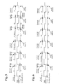
- Figure 6 illustrates the response to the step of this approach. From this there is an almost instant recovery of the variation in speed of the motor and a correct phase relationship.
- Period n Period ⁇ n - 1 + K ⁇ 1 * Delta - K ⁇ 2 * Delta ⁇ n - 1
- K1 and K2 are generic parameters whose value can be established according to the filtering needs that could also change during the various driving phases: for example the couple of values [2, 1] could be used during the acceleration phase of the motor and the couple of values [0.5, 0.25] once a steady speed has been reached.
- Figure 7 represents the response to the step of suchtwo couples of values for [K1, K2].
- the new method does not constrain in any way the freedom of the system in the detection of the ZCs. At each ZC it can be decided whether to act according to the method of the prior art or to adopt the one described here.
Landscapes
- Engineering & Computer Science (AREA)
- Power Engineering (AREA)
- Control Of Motors That Do Not Use Commutators (AREA)
Claims (9)
- Procédé de détection de la position angulaire d'un moteur électrique sans balais, comprenant une étape consistant à émettre un signal de polarité de la force contre-électromotrice (Bemf) par un circuit de détection associé au moteur, et à détecter un passage par zéro (ZC) attendu de la force contre-électromotrice (Bemf), caractérisé en ce qu'il comprend les étapes consistant à masquer temporairement la sortie du circuit de détection pendant une période de décroissance de courant autour du passage par zéro (ZC) attendu, à mesurer la différence de durée entre des états logiques "0" et "1" au niveau de la sortie du circuit de détection à l'aide d'un compteur numérique montée/descente, qui est activé dans une période temporelle adjacente à la période de décroissance de courant, ladite fenêtre temporelle étant symétrique par rapport au passage par zéro (ZC) attendu et l'étape de mesure comprenant une étape consistant à augmenter ou diminuer le compte du compteur en même temps que la réception en entrée d'un état logique "0", et à diminuer, si le compte du compteur est augmenté avec la réception en entrée d'un état logique "0", ou à augmenter, si le compte du compteur est diminué avec la réception en entrée d'un état logique "0", le compte du compteur en même temps que la réception en entrée d'un état logique "1" et à déterminer la position angulaire à partir de la valeur du compteur à la fin de la fenêtre temporelle.
- Procédé selon la revendication 1, caractérisé en ce que la durée de la fenêtre temporelle varie arbitrairement pendant le pilotage du moteur.
- Procédé selon la revendication 1, caractérisé en ce qu'il comprend en outre une étape de remise à zéro du compteur ayant lieu au début de chaque fenêtre temporelle ou dans tous les cas à un instant arbitraire avant cette fenêtre temporelle.
- Procédé selon la revendication 3, caractérisé en ce qu'il comprend en outre une étape consistant à faire varier la fréquence de mesure du compteur pendant les diverses phases de pilotage du moteur.
- Procédé selon la revendication 1, caractérisé en ce qu'il comprend en outre une étape consistant à estimer la position instantanée du rotor, la période entre deux passages par zéro (ZC) et la vitesse de rotation en utilisant dans des formules la valeur prise par le compteur à la fin de chaque fenêtre temporelle.
- Procédé selon la revendication 5, caractérisé en ce qu'il comprend en outre un algorithme de filtrage calculant la durée de la période entre deux passages par zéro (ZC) successifs, qui opère selon la relation suivante :

où :"Period(n-1)" résulte du calcul effectué à la fin de la fenêtre temporelle précédente,Delta est le calcul effectué à la fin de la dernière fenêtre temporelle et est la valeur filtrée de l'information de position du passage par zéro (ZC) réel par rapport à celui attendu à la base ; et"Period(n)" est la durée écoulée depuis le passage par zéro (ZC) précédent calculée à la fin de la dernière fenêtre temporelle ; etK1 et K2 sont des paramètres génériques dont la valeur peut être établie en fonction des exigences du filtrage. - Procédé selon la revendication 6, caractérisé en ce qu'il comprend en outre une étape consistant à modifier arbitrairement la valeur des paramètres pendant les diverses phases de pilotage du moteur.
- Procédé selon la revendication 1, caractérisé en ce qu'il comprend en outre une étape consistant à désactiver périodiquement le compteur pour l'empêcher de mesurer aussi à l'intérieur de la fenêtre temporelle.
- Procédé selon la revendication 6, caractérisé en ce qu'il est arbitrairement alterné avec un procédé quelconque de l'art antérieur pour détecter la position du rotor.
Priority Applications (3)
| Application Number | Priority Date | Filing Date | Title |
|---|---|---|---|
| DE60233416T DE60233416D1 (de) | 2002-11-28 | 2002-11-28 | Verfahren zum Erfassen der Winkelposition eines kommutatorlosen elektrischen Motors |
| EP02425725A EP1424768B1 (fr) | 2002-11-28 | 2002-11-28 | Procédé de détection de la position angulaire d'un moteur électrique sans balais |
| US10/721,766 US7235939B2 (en) | 2002-11-28 | 2003-11-25 | Method for detecting the angular position of a rotor in a brushless electric motor |
Applications Claiming Priority (1)
| Application Number | Priority Date | Filing Date | Title |
|---|---|---|---|
| EP02425725A EP1424768B1 (fr) | 2002-11-28 | 2002-11-28 | Procédé de détection de la position angulaire d'un moteur électrique sans balais |
Publications (2)
| Publication Number | Publication Date |
|---|---|
| EP1424768A1 EP1424768A1 (fr) | 2004-06-02 |
| EP1424768B1 true EP1424768B1 (fr) | 2009-08-19 |
Family
ID=32241380
Family Applications (1)
| Application Number | Title | Priority Date | Filing Date |
|---|---|---|---|
| EP02425725A Expired - Lifetime EP1424768B1 (fr) | 2002-11-28 | 2002-11-28 | Procédé de détection de la position angulaire d'un moteur électrique sans balais |
Country Status (3)
| Country | Link |
|---|---|
| US (1) | US7235939B2 (fr) |
| EP (1) | EP1424768B1 (fr) |
| DE (1) | DE60233416D1 (fr) |
Families Citing this family (16)
| Publication number | Priority date | Publication date | Assignee | Title |
|---|---|---|---|---|
| EP1424768B1 (fr) * | 2002-11-28 | 2009-08-19 | STMicroelectronics S.r.l. | Procédé de détection de la position angulaire d'un moteur électrique sans balais |
| JP4343007B2 (ja) * | 2004-04-01 | 2009-10-14 | 株式会社東芝 | 情報処理装置 |
| EP1845610A1 (fr) * | 2006-04-14 | 2007-10-17 | STMicroelectronics S.r.l. | Dispositif de contrôle de la position du rotor d'un moteur électrique et procédé correspondant |
| GB0717851D0 (en) | 2007-09-13 | 2007-10-24 | Melexis Nv | Improvements relating to driving brushless dc (bldc) motors |
| MX2010003444A (es) * | 2007-09-27 | 2010-04-21 | Mitsubishi Electric Corp | Controlador de maquina electrica rotatoria. |
| BRPI0705049B1 (pt) * | 2007-12-28 | 2019-02-26 | Embraco Indústria De Compressores E Soluções Em Refrigeração Ltda | Compressor de gás movido por um motor linear, tendo um detector de impacto entre um cilindro e um pistão, método de detecção e sistema de controle |
| US8237385B2 (en) * | 2008-09-15 | 2012-08-07 | Texas Instruments Incorporated | Systems and methods for detecting position for a brushless DC motor |
| US20100141191A1 (en) * | 2008-12-04 | 2010-06-10 | Chen Liyong | Systems and methods for determining a commutation state for a brushless dc motor |
| US8148928B2 (en) * | 2009-06-30 | 2012-04-03 | Semiconductor Components Industries, Llc | Method for starting a brushless sensorless DC motor |
| US8269444B2 (en) * | 2010-04-06 | 2012-09-18 | Inergy Technology Inc. | System and method for controlling sensorless motor |
| CN102045020B (zh) * | 2011-01-24 | 2013-01-23 | 东元总合科技(杭州)有限公司 | 永磁电机转子位置检测方法 |
| US9099954B2 (en) | 2013-07-25 | 2015-08-04 | Caterpillar Inc. | Enforced zero voltage loop |
| US9726726B2 (en) * | 2014-11-06 | 2017-08-08 | Rockwell Automation Technologies, Inc. | Single-pole, single current path switching system and method |
| US10644624B1 (en) | 2018-12-27 | 2020-05-05 | Johnson Controls Technology Company | Systems and methods for back electromotive force based feedback for a movable component |
| US11303235B2 (en) | 2019-04-25 | 2022-04-12 | Black & Decker Inc. | Dual-controller system for a sensorless brushless motor control |
| US11973445B2 (en) | 2021-05-13 | 2024-04-30 | Johnson Controls Tyco IP Holdings LLP | Actuator with automatic force setting and self-calibration |
Family Cites Families (38)
| Publication number | Priority date | Publication date | Assignee | Title |
|---|---|---|---|---|
| US4492903A (en) * | 1977-05-23 | 1985-01-08 | Nu-Tech Industries, Inc. | Optimum efficiency brushless DC motor |
| US4376970A (en) * | 1980-12-22 | 1983-03-15 | Kearney & Trecker Corporation | High speed digital position monitoring system |
| DE3602227A1 (de) * | 1986-01-25 | 1987-07-30 | Philips Patentverwaltung | Kommutierungsschaltung fuer einen kollektorlosen gleichstrommotor |
| JP2875529B2 (ja) * | 1987-10-31 | 1999-03-31 | ソニー株式会社 | センサレスブラシレスモータの駆動装置 |
| US4922169A (en) * | 1988-10-04 | 1990-05-01 | Miniscribe Corporation | Method and apparatus for driving a brushless motor |
| JPH04236190A (ja) * | 1991-01-11 | 1992-08-25 | Toyota Motor Corp | ブラシレスモータのための電気制御装置 |
| US5130620A (en) * | 1991-01-29 | 1992-07-14 | Matsushita Electric Industrial Co., Ltd. | Brushless DC motor without a position sensor |
| US5506487A (en) * | 1991-03-28 | 1996-04-09 | General Electric Company | Systems and methods for driving a compressor with a motor |
| US5221881A (en) * | 1991-10-03 | 1993-06-22 | Sgs-Thomson Microelectronics, Inc. | Method and apparatus for operating polyphase DC motors |
| US5317243A (en) * | 1991-10-03 | 1994-05-31 | Sgs-Thomson Microelectronics, Inc. | Method and apparatus for detecting velocity profiles of a spinning rotor of a polyphase DC motor |
| US5306988A (en) * | 1991-10-03 | 1994-04-26 | Sgs-Thomson Microelectronics, Inc. | Method and apparatus for operating polyphase dc motors |
| US5384527A (en) * | 1993-05-12 | 1995-01-24 | Sundstrand Corporation | Rotor position detector with back EMF voltage estimation |
| US5672948A (en) * | 1993-06-14 | 1997-09-30 | Cambridge Aeroflo, Inc. | Digital, Back EMF, single coil sampling, sensorless commutator system for a D.C. motor |
| US5663618A (en) * | 1994-03-30 | 1997-09-02 | Zexel Corporation | Driving apparatus for a commutatorless DC motor |
| US5469112A (en) * | 1994-08-15 | 1995-11-21 | Motorola, Inc. | Communication device with zero-crossing demodulator |
| US6504328B1 (en) * | 1995-02-24 | 2003-01-07 | Stmicroelectronics Inc. | Sensorless motor driver with BEMF mask extender |
| KR0154853B1 (ko) * | 1995-08-23 | 1998-12-15 | 김광호 | 모델 추종형 정류 회로와 그 제어 방법 |
| KR0158614B1 (ko) * | 1995-11-28 | 1998-12-15 | 김광호 | 모오스-스타트 회로 및 그 제어 방법 |
| DE69613810T2 (de) * | 1996-04-04 | 2001-10-25 | Stmicroelectronics S.R.L., Agrate Brianza | Synchronsteuerung der Phasenwicklungen eines Gleichstrommotors mit vorbestimmten digitalisierten permanent gespeicherten Ansteuerungsprofilen, deren Auslesung mit der Rotorstellung synchronisiert ist zur Optimierung des Drehmomentsverlaufs |
| US6163120A (en) * | 1996-12-17 | 2000-12-19 | Stmicroelectronics, Inc. | Simple back emf reconstruction in pulse width modulation (PWM) mode |
| US6091222A (en) * | 1997-06-30 | 2000-07-18 | Stmicroelectronics, Inc. | Statistical phase detection and go start-up algorithm |
| DE69831776T2 (de) * | 1997-07-15 | 2006-08-17 | Stmicroelectronics S.R.L., Agrate Brianza | Messung der momentanen Stellung des Rotors eines, im tripolaren Modus getriebenen bürstenlosen Gleichstrommotors |
| DE69713773T2 (de) * | 1997-10-08 | 2002-10-17 | Stmicroelectronics S.R.L., Agrate Brianza | Synchronisation der geregelten und der gesteuerten Phasenansteuerung von Gleichstrommotoren |
| US6081091A (en) * | 1999-03-08 | 2000-06-27 | Motorola, Inc. | Motor controller, integrated circuit, and method of controlling a motor |
| JP2000287477A (ja) * | 1999-03-29 | 2000-10-13 | Mitsubishi Electric Corp | モータ駆動装置 |
| US6023141A (en) * | 1999-05-13 | 2000-02-08 | Motorola, Inc. | Method and apparatus for electronically commutating an electric motor |
| US6424106B2 (en) * | 2000-03-31 | 2002-07-23 | Matsushita Electric Industrial Co., Ltd. | Motor |
| US6498446B1 (en) * | 2000-08-31 | 2002-12-24 | Stmicroelectronics, Inc. | System and method for optimizing torque in a polyphase disk drive motor |
| US6534938B1 (en) * | 2001-09-28 | 2003-03-18 | Delta Electronics Inc. | Method and apparatus for driving a sensorless BLDC motor at PWM operation mode |
| US6901212B2 (en) * | 2002-06-13 | 2005-05-31 | Halliburton Energy Services, Inc. | Digital adaptive sensorless commutational drive controller for a brushless DC motor |
| JP3993502B2 (ja) * | 2002-10-21 | 2007-10-17 | 株式会社ルネサステクノロジ | 多相直流モータの回転駆動制御装置および起動方法 |
| US6850022B2 (en) * | 2003-01-15 | 2005-02-01 | Siemens Vdo Automotive Inc. | Method and system for determining electronic commutation in brushless DC machines irrespective of the placement of rotor position sensors |
| EP1424768B1 (fr) * | 2002-11-28 | 2009-08-19 | STMicroelectronics S.r.l. | Procédé de détection de la position angulaire d'un moteur électrique sans balais |
| US6909572B2 (en) * | 2003-05-07 | 2005-06-21 | Stmicroelectronics S.R.L. | Disk drive system and method for operating same |
| US6941822B2 (en) * | 2003-06-10 | 2005-09-13 | Visteon Global Technologies, Inc. | Angular displacement sensing system and method using brushless DC motor commutation hall effect sensors |
| CN100364225C (zh) * | 2003-06-30 | 2008-01-23 | 松下电器产业株式会社 | 无传感器电机驱动装置及其驱动方法 |
| US6879124B1 (en) * | 2004-01-07 | 2005-04-12 | Quan Jiang | Method to detect the true zero-crossing points of the phase back EMF for sensorless control of brushless DC motors |
| JP4698241B2 (ja) * | 2005-02-01 | 2011-06-08 | ルネサスエレクトロニクス株式会社 | モータ駆動装置 |
-
2002
- 2002-11-28 EP EP02425725A patent/EP1424768B1/fr not_active Expired - Lifetime
- 2002-11-28 DE DE60233416T patent/DE60233416D1/de not_active Expired - Lifetime
-
2003
- 2003-11-25 US US10/721,766 patent/US7235939B2/en not_active Expired - Lifetime
Also Published As
| Publication number | Publication date |
|---|---|
| DE60233416D1 (de) | 2009-10-01 |
| US20040154411A1 (en) | 2004-08-12 |
| EP1424768A1 (fr) | 2004-06-02 |
| US7235939B2 (en) | 2007-06-26 |
Similar Documents
| Publication | Publication Date | Title |
|---|---|---|
| EP1424768A1 (fr) | Procédé de détection de la position angulaire d'un moteur électrique sans balais | |
| US5969491A (en) | Detection of instantaneous position of the rotor of a brushless DC motor driven in a tripolar mode | |
| JP6375431B2 (ja) | 永久磁石モータのロータ位置の決定方法 | |
| JP5749288B2 (ja) | ブラシレス永久磁石モータのセンサレス制御 | |
| KR100218547B1 (ko) | 회전자 위치센서없이 다중위상 무브러쉬 전동기 제어방법 및 그 장치 | |
| JP5651203B2 (ja) | 永久磁石モータのロータ位置の決定方法 | |
| US5317243A (en) | Method and apparatus for detecting velocity profiles of a spinning rotor of a polyphase DC motor | |
| EP1537648B1 (fr) | Commande d'une machine electrique a reluctance | |
| EP1091480B1 (fr) | Détection des signaux de courant ou de tension dérivé sans guige d'un enroulement commandé par modulation de largeur d' impulsions | |
| US8461796B2 (en) | Motor drive circuit for driving a synchronous motor | |
| EP2037567A2 (fr) | Améliorations associées à la commande de moteurs CC (BLDC) | |
| EP0536991A1 (fr) | Méthode et appareil pour resynchroniser un rotor en mouvement d'un moteur à courant continu polyphasé | |
| JPH06237596A (ja) | 多相dcモータの動作方法及び装置 | |
| US9270216B2 (en) | Method and device for processing a motor signal | |
| JPH0715482B2 (ja) | 回転速度の計測方法及び装置 | |
| JPH06237594A (ja) | ゼロ交差決定においてpwmチョッピング信号を使用する多相dcモータの動作方法及び装置 | |
| US6094022A (en) | Low jitter zero crossing BEMF detector and motor incorporating the same | |
| EP0892489B1 (fr) | Détection de la position instantanée du rotor d'un moteur à courant continu sans balai commandé en mode tripolaire | |
| US5990656A (en) | Frequency detector | |
| US12224698B2 (en) | Method of controlling a brushless permanent-magnet motor | |
| US20020033688A1 (en) | Start procedure for brushless motors | |
| US7518332B2 (en) | Brushless synchronous motor and driving control apparatus therefor | |
| US11482952B1 (en) | Method for determining zero crossing occurrence in alternating current signal with constant frequency of permanent magnet synchronous motor with high noise immunity and low delay and associated motor device | |
| US8674639B2 (en) | Accuracy of rotor position detection relating to the control of brushless DC motors | |
| JPS61293191A (ja) | ブラシレスモ−タ駆動装置 |
Legal Events
| Date | Code | Title | Description |
|---|---|---|---|
| PUAI | Public reference made under article 153(3) epc to a published international application that has entered the european phase |
Free format text: ORIGINAL CODE: 0009012 |
|
| AK | Designated contracting states |
Kind code of ref document: A1 Designated state(s): AT BE BG CH CY CZ DE DK EE ES FI FR GB GR IE IT LI LU MC NL PT SE SK TR |
|
| AX | Request for extension of the european patent |
Extension state: AL LT LV MK RO SI |
|
| 17P | Request for examination filed |
Effective date: 20041130 |
|
| AKX | Designation fees paid |
Designated state(s): DE FR GB IT |
|
| 17Q | First examination report despatched |
Effective date: 20050506 |
|
| 17Q | First examination report despatched |
Effective date: 20050506 |
|
| 17Q | First examination report despatched |
Effective date: 20050506 |
|
| GRAP | Despatch of communication of intention to grant a patent |
Free format text: ORIGINAL CODE: EPIDOSNIGR1 |
|
| GRAS | Grant fee paid |
Free format text: ORIGINAL CODE: EPIDOSNIGR3 |
|
| GRAA | (expected) grant |
Free format text: ORIGINAL CODE: 0009210 |
|
| AK | Designated contracting states |
Kind code of ref document: B1 Designated state(s): DE FR GB IT |
|
| REG | Reference to a national code |
Ref country code: GB Ref legal event code: FG4D |
|
| REF | Corresponds to: |
Ref document number: 60233416 Country of ref document: DE Date of ref document: 20091001 Kind code of ref document: P |
|
| RAP2 | Party data changed (patent owner data changed or rights of a patent transferred) |
Owner name: STMICROELECTRONICS SRL |
|
| PLBE | No opposition filed within time limit |
Free format text: ORIGINAL CODE: 0009261 |
|
| STAA | Information on the status of an ep patent application or granted ep patent |
Free format text: STATUS: NO OPPOSITION FILED WITHIN TIME LIMIT |
|
| 26N | No opposition filed |
Effective date: 20100520 |
|
| REG | Reference to a national code |
Ref country code: FR Ref legal event code: ST Effective date: 20100730 |
|
| PG25 | Lapsed in a contracting state [announced via postgrant information from national office to epo] |
Ref country code: FR Free format text: LAPSE BECAUSE OF NON-PAYMENT OF DUE FEES Effective date: 20091130 |
|
| PG25 | Lapsed in a contracting state [announced via postgrant information from national office to epo] |
Ref country code: IT Free format text: LAPSE BECAUSE OF FAILURE TO SUBMIT A TRANSLATION OF THE DESCRIPTION OR TO PAY THE FEE WITHIN THE PRESCRIBED TIME-LIMIT Effective date: 20090819 |
|
| PGFP | Annual fee paid to national office [announced via postgrant information from national office to epo] |
Ref country code: GB Payment date: 20211020 Year of fee payment: 20 Ref country code: DE Payment date: 20211020 Year of fee payment: 20 |
|
| REG | Reference to a national code |
Ref country code: DE Ref legal event code: R071 Ref document number: 60233416 Country of ref document: DE |
|
| REG | Reference to a national code |
Ref country code: GB Ref legal event code: PE20 Expiry date: 20221127 |
|
| PG25 | Lapsed in a contracting state [announced via postgrant information from national office to epo] |
Ref country code: GB Free format text: LAPSE BECAUSE OF EXPIRATION OF PROTECTION Effective date: 20221127 |