EP1424850A2 - Appareil photo avec dispositif de déflection pour imager des régions différentes - Google Patents
Appareil photo avec dispositif de déflection pour imager des régions différentes Download PDFInfo
- Publication number
- EP1424850A2 EP1424850A2 EP03026353A EP03026353A EP1424850A2 EP 1424850 A2 EP1424850 A2 EP 1424850A2 EP 03026353 A EP03026353 A EP 03026353A EP 03026353 A EP03026353 A EP 03026353A EP 1424850 A2 EP1424850 A2 EP 1424850A2
- Authority
- EP
- European Patent Office
- Prior art keywords
- receiving device
- optical
- optical receiving
- camera system
- deflection
- Prior art date
- Legal status (The legal status is an assumption and is not a legal conclusion. Google has not performed a legal analysis and makes no representation as to the accuracy of the status listed.)
- Withdrawn
Links
Images
Classifications
-
- G—PHYSICS
- G02—OPTICS
- G02B—OPTICAL ELEMENTS, SYSTEMS OR APPARATUS
- G02B26/00—Optical devices or arrangements for the control of light using movable or deformable optical elements
- G02B26/08—Optical devices or arrangements for the control of light using movable or deformable optical elements for controlling the direction of light
- G02B26/0816—Optical devices or arrangements for the control of light using movable or deformable optical elements for controlling the direction of light by means of one or more reflecting elements
- G02B26/0833—Optical devices or arrangements for the control of light using movable or deformable optical elements for controlling the direction of light by means of one or more reflecting elements the reflecting element being a micromechanical device, e.g. a MEMS mirror, DMD
-
- H—ELECTRICITY
- H04—ELECTRIC COMMUNICATION TECHNIQUE
- H04N—PICTORIAL COMMUNICATION, e.g. TELEVISION
- H04N23/00—Cameras or camera modules comprising electronic image sensors; Control thereof
- H04N23/58—Means for changing the camera field of view without moving the camera body, e.g. nutating or panning of optics or image sensors
Definitions
- the invention relates to a camera system with an optical Receiving device for taking pictures, in particular from inside or from the surroundings of a vehicle and with an optical deflector for feeding the Images of the optical receiving device.
- Micro mirrors (DMD: digital mirror device) is generally known. It is about around mirrors, each of which has a multitude of matrix shapes arranged arranged small mirror elements whose Deflection angle with the help of a control device in each case individually adjustable and therefore changeable are.
- projection systems projection systems for the projection of Image data, especially for presentations.
- the camera systems mentioned above are also basically known from the prior art.
- the at such systems in the field of vehicle technology optical receiving devices used i.e. cameras, are usually based on CCD (charged coupled device) or CMOS (complementary symmetry metal-oxide semiconductor) technology. That of the respective optical Optical deflector associated with the receiving device is usually at a line of sight and thus on an observation area fixedly aligned; for the Different observation areas will be captured therefore previously separate complete camera systems used, each always an expensive optical Include receiving device.
- This approach has the disadvantage that they are not just technical, but is also particularly expensive financially.
- the task is solved at the camera system described in the introduction in particular in that the optical deflection device at least has a micromirror whose deflection angle with the help a control device is variably adjustable so that the optical receiving device in accordance with the each set deflection angle images of different observation areas can.
- the camera system can be used universally without that for taking pictures of different ones Observation areas each separate optical Receiving facilities would be required.
- the different observation areas can be from one position or from different positions, observe from different perspectives.
- the Micromirrors a variety of mirror elements, whose Deflection angle individually with the help of Control device are adjustable. That way it is possible that an image of an observation area is not needs to be fully captured, but can instead, individual dots or areas of the image be hidden by the deflection angle of this Mirror elements capturing image areas at least temporarily be set differently. Even the intensity of the light The images captured by the micromirror can be viewed through rapid change of the deflection angle, i.e. by so-called on / off influence.
- the use of at least two micromirrors in the Optical deflection device has the advantage that this can be positioned at different locations, so that then using the micromirrors of a single one optical receiving device not only images different angles at one position, but also images from different angles different positions / locations can.
- the settings of optical receiving devices and Micromirrors can advantageously be synchronized in such a way i.e. coordinated, that the Image areas of the optical receiving device fed images either not or only in the desired Overlap dimensions.
- An education of the optical receiving device only in The shape of a light receiving diode offers the advantage that an expensive camera device and thus costs saved can be.
- control device or a separate evaluation device is formed, which Data from the optical receiving device to receive captured images and with a view to evaluate the desired criterion.
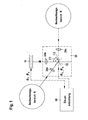
- the camera system has an optical receiving device 10 and an optical deflection device 20.
- the optical receiving device 10 preferably a CCD camera or at least any light receiving diode, is used to record images that are supplied to it by the optical deflection device 20.
- these can each have a different spectral behavior.
- Light receiving diodes offer compared to camera chips, e.g. B. CCD cameras, the advantage that they are dependent on ambient light to a significantly smaller extent than the camera chips.
- the optical deflection device comprises a micromirror 22.
- the deflection angle ⁇ 1, ⁇ 2 of the micromirror 22 or of its individual mirror elements is individually so set that the optical receiving device 10 is supplied with images of different rooms that are currently to be observed, ie in particular from the observation areas A and B.
- the control device 30 synchronizes the recording times of the optical receiving device 10 with the times in which the micromirror 22 provides images; for this purpose, the control device 30 outputs the same clock signal ⁇ 1 ... ⁇ n to both the micromirror 22 and the optical receiving device 10.
- the control device 30 or a separate evaluation device also receives the data of the images recorded by the optical receiving device 10 in order to store and evaluate them.
- micromirror according to the invention 22 Due to the use of the micromirror according to the invention 22 is for the observation of the two observation areas A, B only an optical receiving device required. Compared to the usual use of a separate optical receiver for each Observation area this means an essential Cost savings.
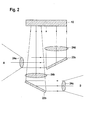
- the optical deflection device 20 has supplied images optical lenses 24a, 24b and 24c in the beam path of the incident on the micromirror 22 and / or of reflect on this.
- An example of an application of the described Camera system with an optical deflector 20, the having only one micromirror 22 is a Night vision device.
- a optical receiving device particularly in the infra-red light area is very sensitive, e.g. a picture of a Street at night depicted on a display.
- Appears at traditional devices of this type are very bright Light source, e.g. in the form of a beaming pig thrower of an oncoming vehicle, in the picture, becomes a large area of the image fades. As a result, that details behind or to the side of the light source on the Image are no longer visible.
- the claimed optical optical deflection device 20 with the micromirror 22 can be a single image area, here e.g.
- FIG. 2 shows a second embodiment of the invention, which differs from the first exemplary embodiment according to FIG. 1 essentially differs in that the optical Deflection device 20 here not only one, but two Micromirrors 22a and 22b.
- the one on the two Micromirror with incident light rays Image information from the different Observation areas A and B are over optical lenses 24a to 24d to the optical receiving device 10 forwarded.
- the two observation areas must be exemplary embodiments A and B no longer from the position of a single one Micromirror from be observable, but can instead lie in very different places because also the two micromirrors 22a and 22b used here can be positioned at different locations.
- An example of using a camera system with multiple micromirrors is the control and adjustment the correct position of seats in vehicles Airbags.
- a camera system with multiple micromirrors For the detection of a current sitting position with Help of the principle of triangulation it is necessary the distances of the seat to different reference points in the Vehicle, i.e. e.g. to the dashboard and to the right and left vehicle door to determine.
- several camera systems positioned separately each with its own optical receiver for The present offers the determination of the individual distances Invention the possibility of the distances sought by the Use of inexpensive, locally separated positions Micromirrors 22a and 22b and with only one optical one Detect receiving device 10.
- the times when the two micromirrors 22a, 22b the pictures with the local conditions in Transmit the vehicle to the optical receiving device 10 from the control device 30 with the recording times of the optical receiving device advantageously so synchronized, i.e. voted that a reception or a Taking pictures in a given order the optical receiving device is possible; alternative is also a simultaneous or delayed reception of the pictures possible.
- the control device 30 or one receives separate evaluation device (not shown here) then, if necessary, the images together with other necessary data from the optical Receiving device 10, stores the images, evaluates them in With regard to a given distance criterion by it determines the real distances sought from the images and finally computes correction quantities above that Provide information on how the real seating position is changed must be in order for a person to sit safely in the To enable the vehicle even when the airbag is in operation.
- the if necessary change the seating position after Provided by the calculated correction quantities can either done manually or automatically.
- micromirrors in the camera systems described are e.g. the Interior surveillance of vehicles, the detection of Raindrops on the outside and from dirt or Fitting on the inside of windshields or the Observation of areas in front of and behind a vehicle when parking.
Landscapes
- Physics & Mathematics (AREA)
- Engineering & Computer Science (AREA)
- Multimedia (AREA)
- Signal Processing (AREA)
- General Physics & Mathematics (AREA)
- Optics & Photonics (AREA)
- Studio Devices (AREA)
Applications Claiming Priority (2)
| Application Number | Priority Date | Filing Date | Title |
|---|---|---|---|
| DE10255194 | 2002-11-27 | ||
| DE10255194A DE10255194A1 (de) | 2002-11-27 | 2002-11-27 | Kamerasystem |
Publications (2)
| Publication Number | Publication Date |
|---|---|
| EP1424850A2 true EP1424850A2 (fr) | 2004-06-02 |
| EP1424850A3 EP1424850A3 (fr) | 2004-12-15 |
Family
ID=32240447
Family Applications (1)
| Application Number | Title | Priority Date | Filing Date |
|---|---|---|---|
| EP03026353A Withdrawn EP1424850A3 (fr) | 2002-11-27 | 2003-11-18 | Appareil photo avec dispositif de déflection pour imager des régions différentes |
Country Status (2)
| Country | Link |
|---|---|
| EP (1) | EP1424850A3 (fr) |
| DE (1) | DE10255194A1 (fr) |
Cited By (2)
| Publication number | Priority date | Publication date | Assignee | Title |
|---|---|---|---|---|
| WO2012103886A1 (fr) * | 2011-02-02 | 2012-08-09 | Conti Temic Microelectronic Gmbh | Dispositif optique doté d'un moyen électro-optique |
| CN114659623A (zh) * | 2017-02-14 | 2022-06-24 | 京瓷株式会社 | 电磁波检测装置、程序以及信息获取系统 |
Families Citing this family (1)
| Publication number | Priority date | Publication date | Assignee | Title |
|---|---|---|---|---|
| DE102006004260A1 (de) * | 2006-01-31 | 2007-08-02 | Bayerische Motoren Werke Ag | Kamerasystem für ein Kraftfahrzeug |
Family Cites Families (8)
| Publication number | Priority date | Publication date | Assignee | Title |
|---|---|---|---|---|
| JPS51148326A (en) * | 1975-06-16 | 1976-12-20 | Osame Kogyo:Kk | Tv camera |
| DE8807162U1 (de) * | 1988-06-01 | 1988-08-04 | Rebentisch, Wolfgang, 2000 Hamburg | Sehhilfegerät |
| DE4402775C1 (de) * | 1994-01-27 | 1995-07-20 | Mannesmann Ag | Abbildungssystem mit elektronischem Bildsensor |
| DE4416589A1 (de) * | 1994-05-11 | 1995-11-16 | Zeiss Carl Fa | Bildaufnahme- und Wiedergabesystem |
| JPH0843881A (ja) * | 1994-07-29 | 1996-02-16 | Nikon Corp | カメラ |
| AU741296B2 (en) * | 1997-03-05 | 2001-11-29 | Daewoo Electronics Co., Ltd. | Thin film actuated mirror array in an optical projection system and method for manufacturing the same |
| DE29902607U1 (de) * | 1999-02-09 | 1999-08-05 | Schmiedt, Ralf, 32832 Augustdorf | Geräteanordnung im Fahrzeug zum Nachweis von Verkehrssündern, die Parkplatzschäden nicht melden und damit Fahrerflucht begehen |
| DE19941045A1 (de) * | 1999-08-28 | 2001-04-12 | Bosch Gmbh Robert | Mikroschwingvorrichtung |
-
2002
- 2002-11-27 DE DE10255194A patent/DE10255194A1/de not_active Withdrawn
-
2003
- 2003-11-18 EP EP03026353A patent/EP1424850A3/fr not_active Withdrawn
Cited By (2)
| Publication number | Priority date | Publication date | Assignee | Title |
|---|---|---|---|---|
| WO2012103886A1 (fr) * | 2011-02-02 | 2012-08-09 | Conti Temic Microelectronic Gmbh | Dispositif optique doté d'un moyen électro-optique |
| CN114659623A (zh) * | 2017-02-14 | 2022-06-24 | 京瓷株式会社 | 电磁波检测装置、程序以及信息获取系统 |
Also Published As
| Publication number | Publication date |
|---|---|
| DE10255194A1 (de) | 2004-06-09 |
| EP1424850A3 (fr) | 2004-12-15 |
Similar Documents
| Publication | Publication Date | Title |
|---|---|---|
| EP2765031B1 (fr) | Système de vision pour véhicules, notamment véhicules utilitaires | |
| DE60208894T2 (de) | Regensensor mit stereoscopischem abbildungssystem | |
| DE60029335T2 (de) | Überwachungskamera, verfahren zum anpassen einer kamera und fahrzeugüberwachungssystem | |
| DE10258413B4 (de) | Fahrzeugumgebungs-Überwachungsvorrichtung | |
| DE19832317C1 (de) | Anordnung, bei der von einer Lichtquelle aus Licht auf eine Fläche gerichtet wird | |
| EP2623374A1 (fr) | Système de vision pour véhicules utilitaires destiné à la représentation de champs de vision règlementaires d'un rétroviseur principal et d'un rétroviseur grand angle | |
| DE102009000550A1 (de) | Weitwinkelbildgebungssystem für die Bereitstellung eines Bildes der Umgebung eines Fahrzeugs, insbesondere eines Kraftfahrzeugs | |
| EP0907902B1 (fr) | Procede de representation visuelle tridimensionnelle sur une surface de projection a grand ecran a l'aide d'un projecteur a laser | |
| DE3835307A1 (de) | Optisches system zum einbau in eine tuer | |
| DE60215223T2 (de) | Satellitengestütztes optisches beobachtungsinstrument mit zwei teleskopen | |
| DE69718009T2 (de) | System zur optischen detektion | |
| DE102022114245B3 (de) | Kamera-Monitor-System für ein Fahrzeug und Verfahren zur Steuerung eines solchen Kamera-Monitor-Systems | |
| EP1424850A2 (fr) | Appareil photo avec dispositif de déflection pour imager des régions différentes | |
| DE10010443B4 (de) | Optisches Suchersystem | |
| DE102015224185A1 (de) | Vorrichtung zum Erfassen und Anzeigen einer Fahrzeugumgebung in einem Fahrzeug | |
| DE102014224903A1 (de) | Optischer Umfeldsensor für Fahrzeuge | |
| DE102018000485A1 (de) | Optische Erfassungseinrichtung für ein Fahrzeug | |
| DE10112009A1 (de) | Verfahren zum Aufnehmen von Luftbildern für die Luftbildaufklärung und Vorrichtung zum Durchführen eines solchen Verfahrens | |
| DE102006036769B3 (de) | Einrichtung insbesondere zum Echtzeit-Luftbild-Überwachen aus Flugzeugen | |
| DE19950681A1 (de) | Bilderfassungssystem | |
| DE102005006754A1 (de) | Weitwinkeliges Kamera-Spiegel-System für Beobachtungszwecke | |
| DE19907345B4 (de) | Vorrichtung zum Abbilden eines als Raster von Bildpunkten darstellbaren Bildes auf einem Schirm | |
| DE3525526C2 (de) | Laufbild-Filmkamera mit Sucherlupen-Verlängerung | |
| DE102005035830B4 (de) | Panoramisches Abbildungssystem | |
| EP0880722A2 (fr) | Dispositif pour representer des images en mouvement dans des plans situes l'un derriere l'autre |
Legal Events
| Date | Code | Title | Description |
|---|---|---|---|
| PUAI | Public reference made under article 153(3) epc to a published international application that has entered the european phase |
Free format text: ORIGINAL CODE: 0009012 |
|
| AK | Designated contracting states |
Kind code of ref document: A2 Designated state(s): AT BE BG CH CY CZ DE DK EE ES FI FR GB GR HU IE IT LI LU MC NL PT RO SE SI SK TR |
|
| AX | Request for extension of the european patent |
Extension state: AL LT LV MK |
|
| PUAL | Search report despatched |
Free format text: ORIGINAL CODE: 0009013 |
|
| RIN1 | Information on inventor provided before grant (corrected) |
Inventor name: SCHMID, BERND Inventor name: SCHULER, THOMAS |
|
| AK | Designated contracting states |
Kind code of ref document: A3 Designated state(s): AT BE BG CH CY CZ DE DK EE ES FI FR GB GR HU IE IT LI LU MC NL PT RO SE SI SK TR |
|
| AX | Request for extension of the european patent |
Extension state: AL LT LV MK |
|
| AKX | Designation fees paid | ||
| REG | Reference to a national code |
Ref country code: DE Ref legal event code: 8566 |
|
| STAA | Information on the status of an ep patent application or granted ep patent |
Free format text: STATUS: THE APPLICATION IS DEEMED TO BE WITHDRAWN |
|
| 18D | Application deemed to be withdrawn |
Effective date: 20050616 |