EP1424858A2 - Farbradsicherung - Google Patents
Farbradsicherung Download PDFInfo
- Publication number
- EP1424858A2 EP1424858A2 EP03257381A EP03257381A EP1424858A2 EP 1424858 A2 EP1424858 A2 EP 1424858A2 EP 03257381 A EP03257381 A EP 03257381A EP 03257381 A EP03257381 A EP 03257381A EP 1424858 A2 EP1424858 A2 EP 1424858A2
- Authority
- EP
- European Patent Office
- Prior art keywords
- colour wheel
- colour
- bracket
- cover member
- unit
- Prior art date
- Legal status (The legal status is an assumption and is not a legal conclusion. Google has not performed a legal analysis and makes no representation as to the accuracy of the status listed.)
- Granted
Links
Images


Classifications
-
- G—PHYSICS
- G03—PHOTOGRAPHY; CINEMATOGRAPHY; ANALOGOUS TECHNIQUES USING WAVES OTHER THAN OPTICAL WAVES; ELECTROGRAPHY; HOLOGRAPHY
- G03B—APPARATUS OR ARRANGEMENTS FOR TAKING PHOTOGRAPHS OR FOR PROJECTING OR VIEWING THEM; APPARATUS OR ARRANGEMENTS EMPLOYING ANALOGOUS TECHNIQUES USING WAVES OTHER THAN OPTICAL WAVES; ACCESSORIES THEREFOR
- G03B21/00—Projectors or projection-type viewers; Accessories therefor
- G03B21/14—Details
- G03B21/20—Lamp housings
- G03B21/2046—Positional adjustment of light sources
-
- G—PHYSICS
- G03—PHOTOGRAPHY; CINEMATOGRAPHY; ANALOGOUS TECHNIQUES USING WAVES OTHER THAN OPTICAL WAVES; ELECTROGRAPHY; HOLOGRAPHY
- G03B—APPARATUS OR ARRANGEMENTS FOR TAKING PHOTOGRAPHS OR FOR PROJECTING OR VIEWING THEM; APPARATUS OR ARRANGEMENTS EMPLOYING ANALOGOUS TECHNIQUES USING WAVES OTHER THAN OPTICAL WAVES; ACCESSORIES THEREFOR
- G03B21/00—Projectors or projection-type viewers; Accessories therefor
- G03B21/14—Details
- G03B21/28—Reflectors in projection beam
-
- H—ELECTRICITY
- H04—ELECTRIC COMMUNICATION TECHNIQUE
- H04N—PICTORIAL COMMUNICATION, e.g. TELEVISION
- H04N9/00—Details of colour television systems
- H04N9/12—Picture reproducers
- H04N9/31—Projection devices for colour picture display, e.g. using electronic spatial light modulators [ESLM]
- H04N9/3102—Projection devices for colour picture display, e.g. using electronic spatial light modulators [ESLM] using two-dimensional electronic spatial light modulators
- H04N9/3111—Projection devices for colour picture display, e.g. using electronic spatial light modulators [ESLM] using two-dimensional electronic spatial light modulators for displaying the colours sequentially, e.g. by using sequentially activated light sources
- H04N9/3114—Projection devices for colour picture display, e.g. using electronic spatial light modulators [ESLM] using two-dimensional electronic spatial light modulators for displaying the colours sequentially, e.g. by using sequentially activated light sources by using a sequential colour filter producing one colour at a time
-
- H—ELECTRICITY
- H04—ELECTRIC COMMUNICATION TECHNIQUE
- H04N—PICTORIAL COMMUNICATION, e.g. TELEVISION
- H04N9/00—Details of colour television systems
- H04N9/12—Picture reproducers
- H04N9/31—Projection devices for colour picture display, e.g. using electronic spatial light modulators [ESLM]
- H04N9/3141—Constructional details thereof
Definitions
- the present invention relates to colour wheel unit for a video projector, the colour wheel unit comprising a colour wheel, a mounting unit for mounting the colour wheel to a structure and a vibration absorbing member for reducing the transmission of vibration from the colour wheel to a structure to which it is mounted by the mounting unit.
- FIG. 1 is a perspective view illustrating an optical system of a colour liquid crystal display (LCD) projector which can produce a colour image using a single LCD panel.
- LCD liquid crystal display
- white light emitted from a lamp 10 and reflected by a mirror 11 passes through a colour wheel 30 rotatably installed in front of the lamp 10.
- the colour wheel comprises red, blue and green filters 32 and sequentially filters the white light to produce red, blue and green beams as it rotates.
- the colour wheel 30 includes a colour rotating disc 31 rotatably installed such that the colour filters 32 are sequentially arranged on an optical path and a motor 35 for rotating the colour rotating disc 31.
- the filtered light is passed through a rectangular-section glass rod 13 to give the beam a rectangular cross-section.
- the light After emerging from the rod 13, the light passes through an image lens 14, a cold mirror 15, which reflects visible light but transmits infrared light, and a lens 16 which matches the rectangular beam to the area of an LCD device.
- the image generating unit includes the LCD device 18 and a pair of polarization panels 17 provided on respective, opposite sides of the LCD device 18. The image generating unit generates an image using the light emitted from the lamp 10 according to the operation of the LCD device 18.
- the modulated light output by the image generating unit passes through a focusing lens 19 and a projection unit 20.
- the projection unit 20 includes a mirror 21 and a plurality of lenses 22. Then, the modulated light is reflected by a mirror 23 behind a screen 24 which reflects the modulated light onto the screen 24 so that it can be viewed.
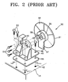
- the colour wheel 30 is a rotating body which rotates at over 9000 rpm., noise is generated by the rotation of the colour rotating disc 31 and vibration of the shaft (not shown) supporting the colour rotating disc 31.
- a conventional colour wheel fixing structure includes a holder 45 for mounting the colour wheel 30 to a base 41.
- a plurality of first threaded holes 38 are provided in a bracket 37 supporting the motor 35.
- a plurality of first through-holes 46 are provided in the holder 45 at positions corresponding to respective first threaded holes 38.
- the colour wheel 30 can be fixed to the holder 45 by screwing a plurality of first screws 51 into the first threaded holes 38 through the first through-holes 46.
- An opening portion 47, through which light passing through the colour wheel 30 can pass, is provided in the holder 45.
- the holder 45 is fixedly installed on the base 41.
- a plurality of second through-holes 48 are provided at the holder 45 and a plurality of second threaded holes 42 are formed in the base 41 at positions corresponding to the second through holes 48.
- the holder 45 can be fixed to the base 41 by screwing a plurality of second screws 53 into the second threaded holes 42 through the second through-holes 48.
- a buffer pad 55 is provided between the base 41 and the holder 45. Thus, as the buffer pad 55 absorbs vibrations of the colour wheel 30 to a degree, noise generated from the colour wheel 30 is reduced.
- the diameter of the colour rotating disc 31 should not be more than 45 mm and rotate at a low speed.
- the number of the colour filters 32 is increased with a concomitant increase in the diameter of the colour rotating disc 31 and simultaneously the speed of rotation of the colour rotation disc 31 is increased. Accordingly, in the colour wheel 30, the colour rotating disc 31 needs to have a diameter of about 50 mm or more and a high rotation speed of over 9000 rpm. When the diameter is increased and a high speed rotation is performed, the noise cannot be reduced by the conventional buffer pad 55 only.
- the present invention may be used instead of the buffer pad for reducing the noise of conventional relatively small and slow colour wheels.
- a colour wheel unit according to the present invention is characterised in that the mounting unit encompasses the colour wheel and the vibration absorbing member is positioned to reduce the transmission of vibration from the colour wheel to the mounting unit.
- the mounting unit comprises first and second portions separated by the vibration absorbing member.
- the first portion comprising fixing means for attaching the colour wheel unit to a structure and the colour wheel is coupled to the first portion via the second portion.
- the unit includes an plate member and the colour wheel is mounted to the plate member and the plate member is mounted to said second portion with the vibration absorbing member interposed between the plate member and said second portion.
- the vibration absorbing member is ring-shaped and the colour wheel is mounted to the plate member through the main aperture in the vibration absorbing member.
- Ring-shaped does not imply circular.
- the plate member supports a holder for supporting an end of a rectangular cross-section transparent rod.
- a rectangular cross-section transparent rod is held by said holder.
- the second portion includes an aperture through which a rod held by the holder can extend.
- a video projector including a structure and a unit according to any preceding claim mounted to the structure by its mounting unit.
- a video projector including a structure and a unit according to the present invention, in which the mounting unit comprises first and second portions separated by the vibration absorbing member, only the first portion comprises fixing means for attaching the colour wheel unit to a structure and the colour wheel is coupled to the first portion via the second portion, mounted to the structure by its mounting unit, and the colour wheel unit is mounted in a margin of the structure and the vibration absorbing member is interposed between the second portion and an edge face substantially normal to a face of said margin to which the first portion is mounted.
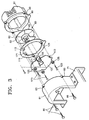
- a colour wheel unit 60 is fixed to a base 71 in a projector.
- the colour wheel unit 60 comprises a colour rotating disc 61 which is rotatably installed, and a motor 63 for rotating the colour rotating disc 61 to rotate.
- a plurality of colour filters 62 are arranged in the colour rotating disc 61 for sequentially filtering white light from a lamp, like the lamp 10 of Figure 1 to produce sequentially red, blue and green beams.
- the colour wheel fixing structure comprises first and second cover members 81, 91 covering the colour wheel 60, a bracket 101 to which the colour wheel 60 is coupled, a coupling unit to couple the bracket 101 to the second cover member 91, and a buffer member 111 which reduces the transmission of vibrations from the colour wheel 60 through the bracket 101 and from the second cover member 91 to the first cover member 81.
- the first cover member 81 is directly coupled to the base 71 but may be indirectly fixed to the base 71 by being coupled to a housing (not shown) housing a glass rod and an LCD panel, similar to or the same as the glass rod 13 and the LCD panel 18 in Figure 1.
- the second cover member 91 and the first cover member 81 are coupled to each other and together encompass.
- a plurality of first through-holes 83 and a plurality of first threaded holes 93 are formed in the first cover member 81 and the second cover member 91 respectively.
- the second cover member 91 is coupled to the first cover member 81 by screwing first screws 85 into the first threaded holes 93 through the first through-holes 83.
- the buffer member 111 is disposed between the first and second cover members 81 and 91 to reduce the transfer of vibration from the second cover member 91 to the first cover member 81.
- the second cover member 91 has a light passing hole 92 to provide a path for light from the lamp and to the colour filters 62.
- the colour wheel 60 is vibrationally and acoustically isolated by the first and second cover members 81, 91.
- the buffer member 111 is provided between the first and second cover members 81, 91 and between the bracket 101 and the second cover member 91.
- the buffer member 111 is a ring-shaped rubber pad and the shape and size of the buffer member 111 are such that it conforms the first and second cover members 81, 91.
- the bracket 101 smaller than the buffer member 111 so that it can be disposed inside when the second cover member 91 is coupled to the first cover member 81.
- the colour wheel 60 is directly coupled to the bracket 101.
- the vibration is directly transferred to the bracket 101. Since the bracket 101 is coupled to the second cover member 91 by the coupling unit C with the buffer member 111 interposed therebetween, the vibration is prevented from being transferred to the second cover member 91.
- the coupling unit C comprises a plurality of second threaded holes 95 formed in the second cover member 91, a plurality of second through-holes 113 formed in the buffer member 111 at positions corresponding to the second threaded holes 95, and a plurality of coupling notches 103 formed in the bracket 101.
- the coupling unit also includes a plurality of bushings 121, a plurality of second screws 123, and a plurality of buffer washers 125.
- the bushings 121 is inserted into respective ones of the second through-holes 113 such that part of the outer side of each of the bushings 121 contacts each of the second coupling notches 103.
- the second screws 123 are coupled to the through-holes 113 by passing through the bushings 121 and the second through-holes 113 so that the bracket 101 is coupled to the second cover member 91.
- Each of the buffer washers 125 is inserted around each of the second screws 123 and disposed at the rear of the bracket 103 so that the vibration of the colour wheel 60 transferred via the bracket 103 is damped.
- a glass rod holder 105 is arranged such that a light incident surface of a glass rod, held by the holder 105, is close to the colour wheel 60 to give the light passing through the colour wheel 60 a rectangular cross-section.
- the colour wheel fixing structure comprises a glass rod holder 105 holding one end of a glass rod which extends through an aperture in the the first cover member 81.
- the buffer member is provided between the first and second cover members, the transfer of the noise due to the rotation of the colour rotating disc of the colour wheel and vibration of the shaft of the colour wheel can be reduced.
Landscapes
- Physics & Mathematics (AREA)
- General Physics & Mathematics (AREA)
- Engineering & Computer Science (AREA)
- Multimedia (AREA)
- Signal Processing (AREA)
- Projection Apparatus (AREA)
Applications Claiming Priority (2)
| Application Number | Priority Date | Filing Date | Title |
|---|---|---|---|
| KR2002034832 | 2002-11-21 | ||
| KR20-2002-0034832U KR200303994Y1 (ko) | 2002-11-21 | 2002-11-21 | 프로젝터용 칼라휠 고정구조체 |
Publications (3)
| Publication Number | Publication Date |
|---|---|
| EP1424858A2 true EP1424858A2 (de) | 2004-06-02 |
| EP1424858A3 EP1424858A3 (de) | 2005-05-25 |
| EP1424858B1 EP1424858B1 (de) | 2008-01-02 |
Family
ID=35431908
Family Applications (1)
| Application Number | Title | Priority Date | Filing Date |
|---|---|---|---|
| EP03257381A Expired - Lifetime EP1424858B1 (de) | 2002-11-21 | 2003-11-21 | Farbradsicherung |
Country Status (4)
| Country | Link |
|---|---|
| US (1) | US6971752B2 (de) |
| EP (1) | EP1424858B1 (de) |
| KR (1) | KR200303994Y1 (de) |
| DE (1) | DE60318375T2 (de) |
Cited By (1)
| Publication number | Priority date | Publication date | Assignee | Title |
|---|---|---|---|---|
| CN102411183A (zh) * | 2010-09-26 | 2012-04-11 | 中强光电股份有限公司 | 色轮模组及投影装置 |
Families Citing this family (14)
| Publication number | Priority date | Publication date | Assignee | Title |
|---|---|---|---|---|
| EP1639406B1 (de) * | 2003-06-02 | 2017-04-05 | Seiko Epson Corporation | Rausch-dämpfer |
| KR100549531B1 (ko) * | 2004-05-08 | 2006-02-03 | 삼성전자주식회사 | 프로젝션 텔레비전 |
| TWI307809B (en) * | 2006-04-04 | 2009-03-21 | Young Optics Inc | Color wheel and assembly method thereof |
| TW200742882A (en) * | 2006-05-03 | 2007-11-16 | Delta Electronics Inc | Projection device and color wheel for use therewith |
| TWI325092B (en) * | 2006-09-22 | 2010-05-21 | Delta Electronics Inc | Color wheel module for use in a projection device and said projection device |
| TWI309334B (en) * | 2006-10-03 | 2009-05-01 | Delta Electronics Inc | Color wheel module for use in a projection apparatus |
| CN100582926C (zh) * | 2007-10-30 | 2010-01-20 | 鸿富锦精密工业(深圳)有限公司 | 投影机 |
| TWI396815B (zh) * | 2008-06-13 | 2013-05-21 | Hon Hai Prec Ind Co Ltd | 彩色燈具 |
| TWI452408B (zh) * | 2012-04-27 | 2014-09-11 | Delta Electronics Inc | 濾光結構及光機系統 |
| CN104834169B (zh) * | 2014-02-07 | 2017-04-12 | 中强光电股份有限公司 | 荧光轮及具有该荧光轮的投影装置 |
| TWI533078B (zh) * | 2014-09-04 | 2016-05-11 | 佳世達科技股份有限公司 | 投影機及其色輪模組 |
| TWI530751B (zh) | 2014-09-11 | 2016-04-21 | 中強光電股份有限公司 | 色輪及投影裝置 |
| CN111752079B (zh) * | 2019-03-28 | 2022-05-06 | 中强光电股份有限公司 | 波长转换装置及投影机 |
| CN214795548U (zh) * | 2021-04-13 | 2021-11-19 | 中强光电股份有限公司 | 转轮 |
Family Cites Families (7)
| Publication number | Priority date | Publication date | Assignee | Title |
|---|---|---|---|---|
| DE29614692U1 (de) * | 1996-04-30 | 1996-10-24 | Balzers Prozess Systeme Vertriebs- und Service GmbH, 81245 München | Farbrad und Bilderzeugungsvorrichtung mit einem Farbrad |
| US6024453A (en) * | 1997-04-29 | 2000-02-15 | Balzers Aktiengesellshaft | Method of rapidly producing color changes in an optical light path |
| US6755554B2 (en) | 2000-05-25 | 2004-06-29 | Matsushita Electric Industrial Co., Ltd. | Color wheel assembly and color sequential display device using the same, color wheel unit and color sequential display device using the same, and color sequential display device |
| JP2003156796A (ja) * | 2001-11-20 | 2003-05-30 | Fuji Photo Optical Co Ltd | 冷却ファン一体型回転光学フィルタ装置および照明光学系 |
| TW534335U (en) * | 2002-09-11 | 2003-05-21 | Delta Electronics Inc | Filter wheel module of image display device |
| TW577550U (en) * | 2002-10-02 | 2004-02-21 | Prodisc Technology Inc | Color wheel and washer for color wheel |
| US6896376B2 (en) * | 2002-10-17 | 2005-05-24 | Prodisc Technology Inc. | Color wheel and motor for the same |
-
2002
- 2002-11-21 KR KR20-2002-0034832U patent/KR200303994Y1/ko not_active Expired - Fee Related
-
2003
- 2003-11-17 US US10/714,402 patent/US6971752B2/en not_active Expired - Fee Related
- 2003-11-21 EP EP03257381A patent/EP1424858B1/de not_active Expired - Lifetime
- 2003-11-21 DE DE60318375T patent/DE60318375T2/de not_active Expired - Lifetime
Cited By (1)
| Publication number | Priority date | Publication date | Assignee | Title |
|---|---|---|---|---|
| CN102411183A (zh) * | 2010-09-26 | 2012-04-11 | 中强光电股份有限公司 | 色轮模组及投影装置 |
Also Published As
| Publication number | Publication date |
|---|---|
| DE60318375D1 (de) | 2008-02-14 |
| DE60318375T2 (de) | 2008-12-24 |
| EP1424858A3 (de) | 2005-05-25 |
| US6971752B2 (en) | 2005-12-06 |
| EP1424858B1 (de) | 2008-01-02 |
| KR200303994Y1 (ko) | 2003-02-11 |
| US20040145707A1 (en) | 2004-07-29 |
Similar Documents
| Publication | Publication Date | Title |
|---|---|---|
| EP1424858B1 (de) | Farbradsicherung | |
| CN101261431B (zh) | 保持结构以及投射型显示装置 | |
| US7967453B2 (en) | Holding structure for holding a member in an external cabinet | |
| US7114811B2 (en) | Optical assembly and projector | |
| KR100213104B1 (ko) | 영상 투사장치의 칼라 휠 | |
| KR20050113711A (ko) | 프로젝션 텔레비전 | |
| JP4366618B2 (ja) | 液晶プロジェクタ | |
| KR100549531B1 (ko) | 프로젝션 텔레비전 | |
| JP2006162651A (ja) | カラーホイール装置及びプロジェクタ装置 | |
| US7724313B2 (en) | Automatic dust-removing device for a liquid crystal panel and projector using the same | |
| JPH04181938A (ja) | 投写型表示装置 | |
| JP5910394B2 (ja) | 画像表示装置 | |
| KR200342881Y1 (ko) | 프로젝터용 칼라휠 어셈블리 | |
| JP2000241880A (ja) | 光学装置 | |
| KR200145216Y1 (ko) | 프로젝터용 스크램블러 고정구조체 | |
| KR100223193B1 (ko) | 다목적 프로젝션 디스플레이장치 | |
| KR20070100579A (ko) | 화소 증진 조립체 및 이를 포함하는 영상투사장치 | |
| KR100534138B1 (ko) | 광학엔진장치 | |
| JP2007226030A (ja) | 光学部品保持部材およびプロジェクタ | |
| KR0134054Y1 (ko) | 투사형화상표시장치의 램프 고정구조 | |
| JPH1195159A (ja) | 光学視覚装置 | |
| KR100761116B1 (ko) | 프로젝션 시스템 | |
| KR100236906B1 (ko) | 색합성프리즘에 액정이 부착된 lcd 프로젝터 | |
| CN120972440A (zh) | 光束传递模块及投影装置 | |
| KR200145214Y1 (ko) | 프로젝터용 스크램블러 고정구조 |
Legal Events
| Date | Code | Title | Description |
|---|---|---|---|
| PUAI | Public reference made under article 153(3) epc to a published international application that has entered the european phase |
Free format text: ORIGINAL CODE: 0009012 |
|
| AK | Designated contracting states |
Kind code of ref document: A2 Designated state(s): AT BE BG CH CY CZ DE DK EE ES FI FR GB GR HU IE IT LI LU MC NL PT RO SE SI SK TR |
|
| AX | Request for extension of the european patent |
Extension state: AL LT LV MK |
|
| PUAL | Search report despatched |
Free format text: ORIGINAL CODE: 0009013 |
|
| AK | Designated contracting states |
Kind code of ref document: A3 Designated state(s): AT BE BG CH CY CZ DE DK EE ES FI FR GB GR HU IE IT LI LU MC NL PT RO SE SI SK TR |
|
| AX | Request for extension of the european patent |
Extension state: AL LT LV MK |
|
| RIC1 | Information provided on ipc code assigned before grant |
Ipc: 7G 02B 7/00 B Ipc: 7H 04N 9/31 A Ipc: 7F 21S 10/00 B Ipc: 7F 21V 9/10 B |
|
| 17P | Request for examination filed |
Effective date: 20051104 |
|
| AKX | Designation fees paid |
Designated state(s): DE FR GB NL |
|
| GRAP | Despatch of communication of intention to grant a patent |
Free format text: ORIGINAL CODE: EPIDOSNIGR1 |
|
| RIN1 | Information on inventor provided before grant (corrected) |
Inventor name: LEE, HEONG-SEOG |
|
| GRAS | Grant fee paid |
Free format text: ORIGINAL CODE: EPIDOSNIGR3 |
|
| GRAA | (expected) grant |
Free format text: ORIGINAL CODE: 0009210 |
|
| AK | Designated contracting states |
Kind code of ref document: B1 Designated state(s): DE FR GB NL |
|
| REG | Reference to a national code |
Ref country code: GB Ref legal event code: FG4D |
|
| REF | Corresponds to: |
Ref document number: 60318375 Country of ref document: DE Date of ref document: 20080214 Kind code of ref document: P |
|
| EN | Fr: translation not filed | ||
| PLBE | No opposition filed within time limit |
Free format text: ORIGINAL CODE: 0009261 |
|
| STAA | Information on the status of an ep patent application or granted ep patent |
Free format text: STATUS: NO OPPOSITION FILED WITHIN TIME LIMIT |
|
| 26N | No opposition filed |
Effective date: 20081003 |
|
| PG25 | Lapsed in a contracting state [announced via postgrant information from national office to epo] |
Ref country code: FR Free format text: LAPSE BECAUSE OF FAILURE TO SUBMIT A TRANSLATION OF THE DESCRIPTION OR TO PAY THE FEE WITHIN THE PRESCRIBED TIME-LIMIT Effective date: 20081024 |
|
| PGFP | Annual fee paid to national office [announced via postgrant information from national office to epo] |
Ref country code: DE Payment date: 20091119 Year of fee payment: 7 |
|
| PGFP | Annual fee paid to national office [announced via postgrant information from national office to epo] |
Ref country code: NL Payment date: 20091104 Year of fee payment: 7 |
|
| PGFP | Annual fee paid to national office [announced via postgrant information from national office to epo] |
Ref country code: GB Payment date: 20091118 Year of fee payment: 7 |
|
| REG | Reference to a national code |
Ref country code: NL Ref legal event code: V1 Effective date: 20110601 |
|
| GBPC | Gb: european patent ceased through non-payment of renewal fee |
Effective date: 20101121 |
|
| PG25 | Lapsed in a contracting state [announced via postgrant information from national office to epo] |
Ref country code: NL Free format text: LAPSE BECAUSE OF NON-PAYMENT OF DUE FEES Effective date: 20110601 |
|
| REG | Reference to a national code |
Ref country code: DE Ref legal event code: R119 Ref document number: 60318375 Country of ref document: DE Effective date: 20110601 Ref country code: DE Ref legal event code: R119 Ref document number: 60318375 Country of ref document: DE Effective date: 20110531 |
|
| PG25 | Lapsed in a contracting state [announced via postgrant information from national office to epo] |
Ref country code: GB Free format text: LAPSE BECAUSE OF NON-PAYMENT OF DUE FEES Effective date: 20101121 |
|
| PG25 | Lapsed in a contracting state [announced via postgrant information from national office to epo] |
Ref country code: DE Free format text: LAPSE BECAUSE OF NON-PAYMENT OF DUE FEES Effective date: 20110531 |