EP1425963A2 - Dezentralisierte Sauerstoffversorgungsanlage für Aquakultur - Google Patents
Dezentralisierte Sauerstoffversorgungsanlage für Aquakultur Download PDFInfo
- Publication number
- EP1425963A2 EP1425963A2 EP03027293A EP03027293A EP1425963A2 EP 1425963 A2 EP1425963 A2 EP 1425963A2 EP 03027293 A EP03027293 A EP 03027293A EP 03027293 A EP03027293 A EP 03027293A EP 1425963 A2 EP1425963 A2 EP 1425963A2
- Authority
- EP
- European Patent Office
- Prior art keywords
- oxygen
- containment vessel
- aqueous medium
- containment
- aeration devices
- Prior art date
- Legal status (The legal status is an assumption and is not a legal conclusion. Google has not performed a legal analysis and makes no representation as to the accuracy of the status listed.)
- Granted
Links
- QVGXLLKOCUKJST-UHFFFAOYSA-N atomic oxygen Chemical compound [O] QVGXLLKOCUKJST-UHFFFAOYSA-N 0.000 title claims abstract description 325
- 239000001301 oxygen Substances 0.000 title claims abstract description 325
- 229910052760 oxygen Inorganic materials 0.000 title claims abstract description 325
- 238000009360 aquaculture Methods 0.000 title claims abstract description 28
- 244000144974 aquaculture Species 0.000 title abstract description 24
- 241001465754 Metazoa Species 0.000 claims abstract description 79
- 239000012736 aqueous medium Substances 0.000 claims abstract description 45
- 239000012530 fluid Substances 0.000 claims abstract description 40
- 238000000034 method Methods 0.000 claims abstract description 31
- 238000004891 communication Methods 0.000 claims abstract description 22
- 241000238557 Decapoda Species 0.000 claims abstract description 17
- 238000005273 aeration Methods 0.000 claims description 51
- 238000012545 processing Methods 0.000 claims description 19
- 235000013305 food Nutrition 0.000 claims description 16
- 230000033001 locomotion Effects 0.000 claims description 14
- CBENFWSGALASAD-UHFFFAOYSA-N Ozone Chemical compound [O-][O+]=O CBENFWSGALASAD-UHFFFAOYSA-N 0.000 claims description 11
- 239000007789 gas Substances 0.000 claims description 10
- 239000003814 drug Substances 0.000 claims description 9
- 238000003306 harvesting Methods 0.000 claims description 5
- 239000002028 Biomass Substances 0.000 claims description 3
- 230000000295 complement effect Effects 0.000 claims description 3
- 239000002609 medium Substances 0.000 claims description 3
- 239000010802 sludge Substances 0.000 claims description 3
- 238000012546 transfer Methods 0.000 claims description 3
- 238000010521 absorption reaction Methods 0.000 claims description 2
- XLYOFNOQVPJJNP-UHFFFAOYSA-N water Substances O XLYOFNOQVPJJNP-UHFFFAOYSA-N 0.000 description 61
- QGZKDVFQNNGYKY-UHFFFAOYSA-N Ammonia Chemical compound N QGZKDVFQNNGYKY-UHFFFAOYSA-N 0.000 description 22
- 239000000654 additive Substances 0.000 description 16
- 238000005276 aerator Methods 0.000 description 16
- 238000004519 manufacturing process Methods 0.000 description 15
- MYMOFIZGZYHOMD-UHFFFAOYSA-N Dioxygen Chemical compound O=O MYMOFIZGZYHOMD-UHFFFAOYSA-N 0.000 description 14
- 229910021529 ammonia Inorganic materials 0.000 description 11
- 230000008569 process Effects 0.000 description 11
- 238000009826 distribution Methods 0.000 description 9
- 239000000126 substance Substances 0.000 description 8
- 238000012544 monitoring process Methods 0.000 description 7
- 241000894006 Bacteria Species 0.000 description 6
- 230000007423 decrease Effects 0.000 description 6
- 241000251468 Actinopterygii Species 0.000 description 5
- 238000009313 farming Methods 0.000 description 5
- 231100000518 lethal Toxicity 0.000 description 5
- 230000001665 lethal effect Effects 0.000 description 5
- 241000894007 species Species 0.000 description 5
- 230000000153 supplemental effect Effects 0.000 description 5
- 229940088594 vitamin Drugs 0.000 description 5
- 239000011782 vitamin Substances 0.000 description 5
- 229930003231 vitamin Natural products 0.000 description 5
- 235000013343 vitamin Nutrition 0.000 description 5
- 239000002699 waste material Substances 0.000 description 5
- IJGRMHOSHXDMSA-UHFFFAOYSA-N Atomic nitrogen Chemical compound N#N IJGRMHOSHXDMSA-UHFFFAOYSA-N 0.000 description 4
- 230000008901 benefit Effects 0.000 description 4
- -1 feed Substances 0.000 description 4
- 238000002347 injection Methods 0.000 description 4
- 239000007924 injection Substances 0.000 description 4
- 230000029553 photosynthesis Effects 0.000 description 4
- 238000010672 photosynthesis Methods 0.000 description 4
- OKTJSMMVPCPJKN-UHFFFAOYSA-N Carbon Chemical compound [C] OKTJSMMVPCPJKN-UHFFFAOYSA-N 0.000 description 3
- 241000195493 Cryptophyta Species 0.000 description 3
- FAPWRFPIFSIZLT-UHFFFAOYSA-M Sodium chloride Chemical compound [Na+].[Cl-] FAPWRFPIFSIZLT-UHFFFAOYSA-M 0.000 description 3
- 229910052799 carbon Inorganic materials 0.000 description 3
- 238000004590 computer program Methods 0.000 description 3
- 238000005094 computer simulation Methods 0.000 description 3
- 229910001882 dioxygen Inorganic materials 0.000 description 3
- 229940079593 drug Drugs 0.000 description 3
- 230000000694 effects Effects 0.000 description 3
- 230000006870 function Effects 0.000 description 3
- 230000036541 health Effects 0.000 description 3
- 230000003601 intercostal effect Effects 0.000 description 3
- 235000013379 molasses Nutrition 0.000 description 3
- 230000036284 oxygen consumption Effects 0.000 description 3
- 230000029058 respiratory gaseous exchange Effects 0.000 description 3
- 239000011780 sodium chloride Substances 0.000 description 3
- 238000001179 sorption measurement Methods 0.000 description 3
- 241000143060 Americamysis bahia Species 0.000 description 2
- 238000013459 approach Methods 0.000 description 2
- 239000000919 ceramic Substances 0.000 description 2
- 230000003247 decreasing effect Effects 0.000 description 2
- 238000010586 diagram Methods 0.000 description 2
- 201000010099 disease Diseases 0.000 description 2
- 208000037265 diseases, disorders, signs and symptoms Diseases 0.000 description 2
- 230000005484 gravity Effects 0.000 description 2
- 239000000463 material Substances 0.000 description 2
- 239000000203 mixture Substances 0.000 description 2
- 229910052757 nitrogen Inorganic materials 0.000 description 2
- 238000006213 oxygenation reaction Methods 0.000 description 2
- 150000003839 salts Chemical class 0.000 description 2
- 239000007787 solid Substances 0.000 description 2
- 238000003860 storage Methods 0.000 description 2
- 238000013517 stratification Methods 0.000 description 2
- 239000002352 surface water Substances 0.000 description 2
- 238000012360 testing method Methods 0.000 description 2
- 241000238424 Crustacea Species 0.000 description 1
- 230000001133 acceleration Effects 0.000 description 1
- 230000001154 acute effect Effects 0.000 description 1
- 230000000996 additive effect Effects 0.000 description 1
- 230000002411 adverse Effects 0.000 description 1
- 230000033228 biological regulation Effects 0.000 description 1
- 238000004364 calculation method Methods 0.000 description 1
- 230000008859 change Effects 0.000 description 1
- 238000006243 chemical reaction Methods 0.000 description 1
- 230000001684 chronic effect Effects 0.000 description 1
- 238000004140 cleaning Methods 0.000 description 1
- 230000003749 cleanliness Effects 0.000 description 1
- 239000000356 contaminant Substances 0.000 description 1
- 230000001419 dependent effect Effects 0.000 description 1
- 230000008021 deposition Effects 0.000 description 1
- 238000009792 diffusion process Methods 0.000 description 1
- 238000004090 dissolution Methods 0.000 description 1
- 238000001704 evaporation Methods 0.000 description 1
- 230000008020 evaporation Effects 0.000 description 1
- 238000003872 feeding technique Methods 0.000 description 1
- 239000003337 fertilizer Substances 0.000 description 1
- 239000013505 freshwater Substances 0.000 description 1
- 239000000446 fuel Substances 0.000 description 1
- 230000002706 hydrostatic effect Effects 0.000 description 1
- 210000000987 immune system Anatomy 0.000 description 1
- 230000006872 improvement Effects 0.000 description 1
- 239000007788 liquid Substances 0.000 description 1
- 238000012423 maintenance Methods 0.000 description 1
- 238000007726 management method Methods 0.000 description 1
- 239000002184 metal Substances 0.000 description 1
- 150000002823 nitrates Chemical class 0.000 description 1
- 150000002826 nitrites Chemical class 0.000 description 1
- 230000000243 photosynthetic effect Effects 0.000 description 1
- 235000017924 poor diet Nutrition 0.000 description 1
- 230000010349 pulsation Effects 0.000 description 1
- 230000009467 reduction Effects 0.000 description 1
- 230000000241 respiratory effect Effects 0.000 description 1
- 210000003019 respiratory muscle Anatomy 0.000 description 1
- 238000012552 review Methods 0.000 description 1
- 238000000926 separation method Methods 0.000 description 1
- 235000015170 shellfish Nutrition 0.000 description 1
- 239000000243 solution Substances 0.000 description 1
- 230000035882 stress Effects 0.000 description 1
- 231100000331 toxic Toxicity 0.000 description 1
- 230000002588 toxic effect Effects 0.000 description 1
- 238000009827 uniform distribution Methods 0.000 description 1
- 238000004065 wastewater treatment Methods 0.000 description 1
Images



Classifications
-
- A—HUMAN NECESSITIES
- A01—AGRICULTURE; FORESTRY; ANIMAL HUSBANDRY; HUNTING; TRAPPING; FISHING
- A01K—ANIMAL HUSBANDRY; AVICULTURE; APICULTURE; PISCICULTURE; FISHING; REARING OR BREEDING ANIMALS, NOT OTHERWISE PROVIDED FOR; NEW BREEDS OF ANIMALS
- A01K63/00—Receptacles for live fish, e.g. aquaria; Terraria
- A01K63/04—Arrangements for treating water specially adapted to receptacles for live fish
- A01K63/042—Introducing gases into the water, e.g. aerators, air pumps
-
- A—HUMAN NECESSITIES
- A01—AGRICULTURE; FORESTRY; ANIMAL HUSBANDRY; HUNTING; TRAPPING; FISHING
- A01K—ANIMAL HUSBANDRY; AVICULTURE; APICULTURE; PISCICULTURE; FISHING; REARING OR BREEDING ANIMALS, NOT OTHERWISE PROVIDED FOR; NEW BREEDS OF ANIMALS
- A01K61/00—Culture of aquatic animals
- A01K61/50—Culture of aquatic animals of shellfish
- A01K61/59—Culture of aquatic animals of shellfish of crustaceans, e.g. lobsters or shrimps
Definitions
- the present invention relates generally to aquaculture farming. More specifically, the invention relates to an oxygen supply system for aquacultural farming of marine animals and methods comprising same.
- Aquaculture is the culture and farming of marine animals such as fish or shellfish.
- Aquaculture of shrimp or other marine animals can be considered extensive, semi-intensive, or intensive.
- Extensive aquaculture facilities provide little or nor control over the environment, i.e., placing animals within a site and allowing them to grow on their own or trapping the animals in special enclosures and holding them until they reach market size.
- Intensive aquaculture facilities provide full control the environment such as temperature, salinity, flow rate, feed type, amount of feed, and light.
- Semi-intensive aquaculture facilities are a hybrid of extensive and intensive operations.
- the dissolved oxygen content of the water within the pond is one of the most important parameters of the water quality since oxygen is a vital condition for all marine animals living in the water and having an aerobic type of respiration.
- the solubility of oxygen within the water is influenced by several factors such as, but not limited to, atmospheric pressure, hydrostatic pressure, pond contaminants such as algae or bacteria, and temperature.
- the dissolved oxygen content of the water should be maintained above 3 mg/l and below about 15 mg/l to avoid stressing or killing the marine animals contained therein.
- Line A in FIG. 1 provides a graph that shows the hourly fluctuations of the percentage of dissolved oxygen in a one-day time period within a typical shrimp pond using continuously running air based aeration devices.
- the most influential factor on the dissolved oxygen content, P is dependent upon light conditions because photosynthesis can only occur via utilization of solar energy.
- photosynthesis starts gradually from the early morning hours and increases the dissolved oxygen content of the water.
- the maximum value of the dissolved oxygen content can be observed early in the afternoon.
- Oxygen levels are usually adequate to meet the needs of the marine organisms within the pond as algae and other organisms release oxygen during the photosynthesis process. From the late afternoon hours, however, photosynthesis is rapidly decreasing and ceases after dark in absence of sunlight.
- plants and/or other organisms respirate during night hours and may further decrease the dissolved oxygen content.
- Lethal oxygen level is the dissolved oxygen content that cannot be tolerated by the given marine animal within a pond for a given period of time.
- supplemental oxygen may be needed when the oxygen consumption rate becomes greater than the available oxygen within the water supply.
- the oxygen consumption of a marine animal can significantly change at a given water temperature depending on the activity of animal and may be related to the oxygen saturation of the water.
- the oxygen consumption rate of marine animals may more than double, for example, during feeding periods. It is believed that increasing the dissolved oxygen content within the water may increase the feed consumption rate of marine animals. Consequently, increasing the feed rate may increase the growth rate.
- U.S. Pat. No. 5,893,337 describes a process for optimizing the growth of fish reared in a pond by injecting oxygen in a controlled quantity before feeding the fish.
- a decrease in dissolved oxygen content may cause stress, and ultimately death, to the marine animals.
- stress may suppress the immune system thereby putting the animal at a greater risk of disease.
- marine animals can sense a decrease of dissolved oxygen content of the water before it causes trouble to its respiration and may search for water of higher oxygen content.
- unlike food it is believed that marine animals cannot sense or detect those areas of higher oxygen within the water from a distance. If this random search for oxygen is unsuccessful and the dissolved oxygen content of the water decreases further, the respiratory motion of the marine animal may increase as long as the oxygen supply to respiratory muscles permits. This can reach a limit whereby further acceleration is hindered by lack of oxygen. Marine animals are tolerant until this level. If the dissolved oxygen content of the water decreases further, the pulsation of the heart slows down and the animal dies after a time depending on the resistance characteristic of the individual species.
- Aeration devices typically mechanically agitate the surface water causing oxygen to diffuse into the water as air and water mix. Examples of these devices include paddlewheels, gravity aerators, u-tubes, venturi aerators, surface aerators, or bubble diffusers (e.g., fine, medium, or coarse bubble diffusers).
- the efficiency of the aeration device is determined by the amount of surface area interface between the water and air and the energy required to produce that interface. Since aerators inject air, the amount of oxygen that can be dissolved in water is limited by the concentration of oxygen in the air (21%). Options to increase the amount of dissolved oxygen in the water with air are, therefore, somewhat limited. Further, due to the demand for higher productivity and stocking densities in intensive aquacultural facilities, the natural oxygen supply from air becomes increasingly insufficient and may be the limiting factor in production.
- blower feed part of the feed may be blown away from the pond or may be eaten by birds.
- the dimensions of the pond may also effect feeding efficiency.
- a blower-type feeder throws feed about 30 meters and it lands in a band about 5 meters wide so that the center of a large square pond would not receive much feed. Additionally, it has a high operating cost in terms of manpower, equipment, and fuel.
- aquaculture farms In addition to food and oxygen, aquaculture farms also need to periodically add feed chemicals, medicine, vitamins and other additives to the containment vessel or pond.
- Chemicals such as ozone, may be added to manage the pond water quality.
- Medicines may be added to protect the marine animals against disease.
- Vitamins may be added to improve the health and appearance of the animals.
- Other additives such as fertilizers, chemicals, or carbon sources (such as molasses) may be added for algae and bacteria control. The addition of these additives to the containment vessel presents a challenge in terms of rapid and even distribution as well as the labor effort.
- the present invention satisfies one, if not all, of the needs of the art by providing a system and a method comprising same for providing oxygen, preferably having a purity level by volume of 30% or greater, preferably 50% or greater, more preferably 60% or greater, for the aquafarming of marine animals.
- a system for providing oxygen having a purity of 30% or greater, for the aquaculture of marine animals comprising: a plurality of containment vessels capable of containing a plurality of marine animals and an aqueous medium; a plurality of oxygen injectors, at least one oxygen injector disposed in at least one location of each of said plurality of containment vessels; and a plurality of oxygen generators, each of said plurality of oxygen generators are in fluid communication with at least one oxygen injector whereby the plurality of oxygen generators provides the containment vessels with an amount of oxygen sufficient to increase the percentage of dissolved oxygen within the aqueous medium.
- a system for controlling the supply of oxygen within a containment vessel for the farming of marine animals comprising: a plurality of containment vessels, each of said containment vessels capable of containing a plurality of marine animals, and an aqueous medium, a plurality of sensors for measuring the content of dissolved oxygen C o within the aqueous medium, a plurality of oxygen injectors, at least one oxygen injector is disposed within at least one location of each of said containment vessels; a plurality of oxygen generators each of said oxygen generators is in fluid communication with at least one of said oxygen injectors wherein said oxygen generators provide the containment vessels with an amount of oxygen sufficient to increase the amount of dissolved oxygen within the aqueous medium above the oxygen content C o ; and a central processing unit in electrical communication with the sensors and at least one oxygen generator wherein the central processing unit compares the oxygen content C o against a set point value C set and activates the at least one oxygen generator when the oxygen content C o is
- this system was used to sense when the dissolved oxygen levels were low and to activate the oxygen generator to introduce oxygen via the oxygen injectors into the pond when the level of dissolved oxygen fell below 4 milligram/liter (mg/l), and the oxygen generator was shut off when the dissolved oxygen was above 6 mg/l.
- the results of the the field test and the variation in the dissolved oxygen during the day is shown as Line B in FIG. 1.
- the amount of dissolved oxygen was maintained at a more even level throughout a twenty-four hour period using less energy than if the prior art mechanical aeration devices were run continuously.
- the inventors determined that it is more efficient and necessary for the maintenance of the desired dissolved oxygen levels to add more oxygen to the pond at night than during the day.
- a process for optimizing the growth rate of a plurality of marine animals by improving the consumption of oxygen by the marine animal comprising: providing a vessel capable of containing a plurality of marine animals and water contained therein wherein the water has a dissolved oxygen content C o ; injecting oxygen to the vessel through a plurality of oxygen injectors located within close proximity to the vessel to maintain the dissolved oxygen content C o above a lethal level; and dispensing food to the vessel through the plurality of oxygen injectors wherein the dispensing step is conducted during at least a portion of the injecting step and whereby the marine animal is attracted to the oxygen because it is attracted to the feed.
- the means for moving the aqueous medium using the oxygen injectors and/or other aeration devices that may be present in the containment vessels may be temporarily turned off while the food is dispensed and/or for a period of time prior to and for a period of time after dispensing of the food to provide an opportunity for the marine animals to eat the food before the movement of the aqueous medium deposits the uneaten food into the stagnant areas of the pond.
- a containment vessel for the aquafarming of marine animals comprising one or more aeration devices, and an aqueous medium within said containment vessel, said aeration devices move said aqueous medium to form at least one circular vortex comprising the movement of at least a majority of said aqueous medium in said at least one circular vortex.
- FIG. 1 provides a graph that shows the hourly fluctuations of the percentage of dissolved oxygen in a one-day time period within a typical shrimp pond.
- FIG. 2 provides an illustration of an embodiment of the system of the present invention.
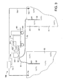
- FIG. 3 provides an illustration of an embodiment of the invention comprising a portable oxygen generator and a monitoring system of this invention.
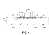
- FIG. 4 provides a cross-sectional view of a containment vessel and a floating oxygen generator useful in a system of this invention.
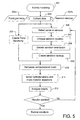
- FIG. 5 provides a process flow diagram for a modeling computer program for the placement of aeration devices in a containment vessel.
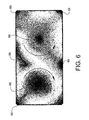
- FIG. 6 provides a top view of the flow patterns within a containment vessel produced by the modeling program outlined in FIG 5.
- FIG. 7 provides a top view of the flow patterns within a containment vessel produced by the modeling program outlined in FIG 5.
- the present invention provides a system and method for delivering gas comprising oxygen, preferably having a purity of 30% or greater via a plurality of oxygen generators located in the proximity of the containment vessels, in a decentralized fashion in an aquaculture facility.
- Previous methods of delivering oxygen such as the delivery of liquid oxygen, do not address the cost effectiveness issues or the infrastructure limitations of aquacultural facilities, which have up to the present time, made high purity oxygen injection impractical.
- having only aeration devices that are limited by the oxygen content of air providing oxygen to a containment vessel is less efficient. This may limit the amount of marine animals that can be raised in a given pond thereby limiting productivity increases.
- aquacultural facilities today practice inefficient methods of injecting feed and other additives to the water.
- the present invention provides a fail-safe method for providing oxygen, along with feed or other additives, to the water within the containment vessel.
- fluid as used herein relates to a flowing fluid composed of a gas, liquid, suspended solids, or combinations thereof.
- pond or “containment vessel” as used herein relates to not only natural or man-made outdoor pond, but also tanks constructed of metal, plastic, concrete, and the like.
- the term "aeration device” includes devices that inject air or gases having a higher concentration of oxygen than air into the water of a containment vessel, including the oxygen generators and oxygen injectors of this invention, and mechanically agitators of the surface water that cause oxygen to diffuse into the water as air and water mix.
- mechanical agitators include paddlewheels, gravity aerators, u-tubes, venturi aerators, surface aerators, or bubble diffusers (e.g., fine, medium, or coarse bubble diffusers).
- the present invention provides a system and process comprising same, which provides a means of producing and distributing oxygen via a gas comprising oxygen to one or more containment vessels in a decentralized fashion.
- the gas preferably is at least 30% by volume oxygen preferably at least 50%, more preferably at least 60% by volume oxygen, and the residue of the gas if any, may comprise mostly nitrogen.
- the dissolved oxygen content for a given containment vessel may be kept and managed within a range of from about 2 mg/l to about 15 mg/l, or more preferably from 4 mg/l to about 12 mg/l.
- stocking density is the weight or number of marine animals held per unit area or volume. Stocking densities may depend on the species of the marine animals and the animals' tolerance to the stress of increased overcrowding. Crustacean species such as shrimp, for example, may begin to fight amongst each other leading to the loss of limbs and reduction in market value if over stocked. Other species of marine animal such as finfish may bite or nip each other on the fins or eyes if overstocked.
- the system and method of the present invention can achieve efficient production at stocking densities of 25 animals per m 3 or greater, preferably 50 animals per m 3 or greater, and more preferably 100 animals per m 3 or greater.
- the system may allow efficient production at shrimp harvest biomass densities of 0.5 kg/m 2 or greater, preferably 1.2 kg/m 2 or greater, and most preferably 2.5 kg/m 2 or greater.
- the biomass density is a measure of the weight of the harvest shrimps per surface area of the pond.
- relatively higher dissolved oxygen levels may allow one to increase the stocking density of the pond.
- FIG. 2 provides one example of an embodiment of the system of the present invention.
- the system 10 is comprised of the following elements: a plurality of containment vessels 20, a plurality of oxygen injectors 30, and a plurality of oxygen generators 40.
- Containment vessel 20 houses a plurality of marine animals 60 within an aqueous medium 50, preferably fresh or salt water depending upon the species of marine animals. (The marine animals 60, and the aqueous medium 50 are shown in the containment vessel 20 shown in Figure 4.)
- Oxygen generators 40 produce oxygen and are in fluid communication with oxygen injectors 30 to distribute oxygen to one or more locations within containment vessels 20. As FIG.
- a plurality of oxygen generators 40 are located throughout system 10 in such a way to provide a primary, as well as a secondary or "back-up" supply, to other containment vessels in the event of failure of one or more other oxygen injectors 30 and/or oxygen generators 40 within the system.
- each containment vessel 20 within system 10 is depicted as receiving oxygen from at least four different oxygen injectors 30 and/or oxygen generators 40.
- the exact location, size, and number of the oxygen injectors and/or generators will vary depending on such factors as system layout, the production capacity of the oxygen generators, the number and size of the containment vessels, and the desired stocking density.
- Each oxygen injector 30 and oxygen generator 40 can be turned on or off anywhere within system 10 depending on the demand for dissolved oxygen in the individual containment vessel 20 or within certain areas of the individual containment vessel 20.
- oxygen generators having one or more oxygen injectors could be located in various locations around or floating in the pond; each oxygen generator could be individually controlled to provide oxygen as needed to the areas of the containment vessel into which one or more oxygen injectors of the oxygen generator are located.
- the systems of this invention will consist of at least 10 ponds, more likely from 20 to more than 1,000 ponds.
- the oxygen generators each have at least one oxygen injector in fluid communication with the oxygen generator.
- Containment vessel 20 may be any vessel that is capable of containing a plurality of marine animals within an aqueous medium such as fresh or salt water. Depending upon the aquacultural facility, containment vessel 20 may be, but is not limited to, raceway, recirculation tanks, canal, pond, or caged areas within an intercostal area. Containment vessel 20 may be located in either an indoor or outdoor aquacultural facility. The volume of the containment vessel may range from a few hundred to a few thousand gallons.
- the size of the pond may range from 1 hectare or below (from 0.1 to 1 hectacre) for intensive aquaculture facilities, from 1 to 2 hectare for semi-intensive aquaculture facilities, and 5 hectare or greater for extensive aquaculture facilities.
- the annual production level, measured in kilogram of marine animal per hectare per harvest, for the intensive, semi-intensive, and extensive aquaculture facilities varies from 5,000 or greater, between 1000 to 5,000, and between 100 to 1,000, respectively.
- oxygen injector 30 preferably is located within close proximity to one or more containment vessels.
- Oxygen injector 30 may also be located within the containment vessel itself such as at one or more sidewalls of the vessel, disposed along the bottom of the containment vessel, or floating along the surface of the containment vessel. It is preferable that in the event that more than one oxygen injector supplies the containment vessel, the oxygen injectors are located complementary with respect to the other's location around or within the containment vessel to ensure a uniform and even distribution of oxygen and other vessel additives (i.e., food, medicine, vitamins, etc.). The placement of the oxygen injectors may be determined via computer simulation of the fluid dynamics within the vessel.
- the location of oxygen injectors 30 should be located to minimize stratification, or the separation of different "layers" of the aqueous medium by distinct boundaries, within containment vessel 20 which can have adverse effects on the marine animals contained therein.
- One or more oxygen injectors 30 can be placed near or at the bottom of the containment vessel to provide sufficient water movement and minimize the occurrence of stratification.
- Oxygen injector 30 may consist of a variety of different types such as aspirator, venturi, bubble diffuser, U-tube, pipeline which preferably contains one or more perforations, column, bicone, or any other injection means.
- oxygen injector 30 and oxygen generator 40 may be integrated into one device such as an oxygen generator with a fixed or flexible attached pipe, diffuser, or the like. It is preferable that oxygen injector 30 is designed to increase the contact surface area, and that the angle or location of the oxygen injector in the pond also increases the contact time between the oxygen and the aqueous medium thereby allowing more oxygen to dissolve into the aqueous medium.
- the oxygen injector may be a venturi.
- a venturi is a device that operates by drawing one fluid media into another using the velocity of the second fluid media (caused by a pressure differential) as the energy source. As the water passes through a restriction in a pipe, it forms a vacuum at the end of the restriction. A hole bored into the pipe at the point where this vacuum occurs may cause air (or any other fluid) to be drawn into the main flow. The amount of fluid drawn in is a direct function of the difference in pressure between the venturi intake and the outlet, and the size of the restriction between them.
- An example of a venturi oxygen injector suitable for use in the system of the present invention is provided in U. S. Pat. No. 5,863,128.
- oxygen generator 40 is in fluid communication with one or more oxygen injectors 30 to supply one or more containment vessels 20.
- Oxygen generator preferably produces oxygen via adsorption techniques such as vacuum swing adsorption (VSA) or pressure swing adsorption (PSA) that removes the nitrogen from the air by a molecule filter.
- VSA vacuum swing adsorption
- PSA pressure swing adsorption
- oxygen generator 40 may be a VSA-based device such as VSA generator model number A150L manufactured by Air Products and Chemicals, Inc. of Allentown, PA the assignee of the present invention.
- Oxygen generator 40 is preferably a portable unit that can be relocated throughout system 10 and attached to one or more oxygen injectors 30 at any time.
- the oxygen generator may be mounted on a movable platform that can be, for example, moved around the periphery of the containment vessels or mounted on a floatable skid and disposed upon the surface of the containment vessel.
- Figure 3 shows oxygen generator 40 on a cart 401 having wheels 402 located adjacent to ponds 20 and providing oxygen to the aqueous medium 50 in the ponds 20 via oxygen injectors 30.
- the oxygen injectors 30 are located at the bottom 201 of the ponds 20.
- the oxygen injectors 30 are provided with holes 31 for a portion 32 of oxygen injectors 30 at the bottom 201 of the ponds 20.
- the oxygen injectors 30 can be made of flexible movable pipe.
- FIG 4 shows an oxygen generator 40 mounted on floatable platform 401 floating on the aqueous medium 50 in containment vessels 20. Marine animals 60 are in the containment vessel 20.
- the oxygen injector 30 shown connected to the oxygen generator 40 has a propeller 39, and a center pipe 37 in which there is an opening (not shown) at its lowermost portion.
- the center pipe is in fluid communication with the oxygen generator 40.
- the gas comprising oxygen is injected into the aqueous medium via the opening in the center pipe 37, and the movement of the propeller 39 helps the diffusion of the oxygen into the water by increasing the surface area of the oxygen in contact with the water.
- the oxygen injector 30 additionally has a floatable platform 38.
- any of the injectors that were described earlier could be used with the oxygen generator shown in Figure 4 to inject the oxygenated gas into the water.
- the oxygen generator 40 shown in Fig 4 may move about the pond or it may be anchored via an anchor (not shown) to a stationary object within or outside of the pond to hold the oxygen generator 40 in a single location, while the propeller 39 causes the aqueous medium 50 to move.
- the oxygen generators 40 are portable and may provide high purity oxygen to any of the containment vessels within system 10 on an as-needed basis. Depending upon its size, the unit capacity of each individual oxygen generator 40 may range from 5 l/min to 5000 l/min of oxygen. As with the oxygen injectors, the number and capacity of the oxygen generators may vary depending upon the system requirements. In certain embodiments, VSA oxygen generators may produce oxygen at a relatively low pressure, e.g., 3 to 5 psi, thereby making them compatible when used to supply low pressure oxygen injectors such as aspirator, venturi, or bubble oxygen injectors. If, however, a higher gas pressure is needed within the system, a booster compressor may be added to the output of the oxygen generator to increase the pressure supplying the oxygen injector.
- a booster compressor may be added to the output of the oxygen generator to increase the pressure supplying the oxygen injector.
- the system of the present invention may be used in conjunction with other aquacultural systems such as, but not limited to, recirculation water treatment systems or aeration systems (i.e., paddle wheel aerators, large volume pumps, etc.). If sufficient water movement can be provided by other systems or means including other aeration devices in a containment vessel or by the oxygen injector alone, then only one oxygen injector present in a containment vessel may be necessary to maintain the dissolved oxygen at a sufficient level to maintain the health of the marine animals.
- recirculation water treatment systems or aeration systems i.e., paddle wheel aerators, large volume pumps, etc.
- the system may dispense feed during at least a portion, or simultaneously with, the oxygen introduction into the containment vessel.
- feed may be added before or after the oxygen is introduced into the containment vessel by the system.
- feed storage bins 500 as shown in Fig 3 are in fluid communication with the one or more oxygen injectors via connection 501.
- the feed is added to the oxygen gas stream or the oxygenated water stream for continual and even feed distribution. Since the oxygen system is operational at most times, feed can be added to the pond on an "as-needed" basis and in appropriate quantities.
- the marine animals can sense and are attracted to the feed while being drawn to the areas having higher dissolved oxygen within the aqueous medium.
- the marine animals may consume higher amounts of dissolved oxygen while consuming the feed. It has been established in references such as Water Quality in Ponds for Aquaculture , Boyd, C. E. (1990), pp. 304-309, which is incorporated herein by reference in its entirety, that higher dissolved oxygen levels may improve feed consumption and lower the feed conversion ratio (e.g., the lbs of feed consumed per lbs of animal) and consequently raise the growth rate while loweing the feed cost. In embodiments wherein the marine animal comprises shrimp, it is desirable that the growth rate be approximately 0.8 to 2.0 gram per week for a 16-24 week production cycle.
- the system of the present invention may also facilitate the introduction of chemicals such as ozone, medicines, vitamins, and/or other additives to the containment vessel by co- injecting these additives with the oxygen gas stream or the oxygenated water stream.
- Medicines, vitamins and other pond additives may be added via hopper 502 and connection 503 in the oxygen injectors 30. This allows for distribution of these additives using the system installed already for oxygen and incurs no additional equipment or labor cost.
- the supply vessels for these additives are in fluid communication with the oxygen injectors. These materials can be added to the pond at any desired time and in as much quantity as needed through the oxygen injectors.
- the ozone generator may be in fluid communication with the oxygen generator to supply oxygen rather than air to the ozone generator that can be converted to ozone.
- the ozone may then be dispensed through the oxygen injector(s).
- Fig 3 shows ozone generator 600 incorporated into the oxygen generator 40.
- the system further comprises a monitoring system.
- the monitoring system may provide the user with certain information, preferably on a real-time basis, on various production parameters, such as temperature, dissolved oxygen, pH, ammonia, nitrates, nitrites, suspended solids, salinity, alkalinity, biochemical oxygen demand (BOD), hardness, turbidity, and water flow rate, within each containment vessel.
- the monitoring system may use this information to activate a variety of different supply sources such as oxygen, feed, medicine, or other additives, on automatic basis.
- One embodiment of the monitoring system 700 as part of the system of this invention is shown in Fig 3.
- the monitoring system 700 preferably consists of a central processing unit 701 that is in electrical communication via direct means, shown as a wire 703 in Fig 3, with one or more sensors 702 and the oxygen generator 40.
- the central processing unit 701 could be in communication with the sensor and/or the oxygen generator via a modem, radio, telecommunication or similar means.
- the monitoring system could. also be in electrical communication with various supply sources such as feed hoppers, ozone generator, oxygen injectors, recirculation tank valves, medicine or other additive sources, and the like.
- Suitable central processing units include, but are not limited to, signal processors, process controllers, microprocessors, computers, or similar devices capable of retaining certain pre-programmed information into memory and performing a variety of functions such as simple algorithms, relaying data, and executing operations.
- the sensors may measure dissolved oxygen levels, temperature, pH, and other water parameters that are in electrical communication with a central processing unit. These parameters would be fed into a central processing unit, which would direct the system elements to provide the necessary injection of oxygen and other materials to the containment vessel in the appropriate quantities. Further, the central processing unit compares these parameters against a number of preset values to determine what each containment vessel needs at any given time.
- the senor 702 can be a sensor that measures the dissolved oxygen in the aqueous medium and the central processing unit 701 may compare the measured oxygen content C o of the aqueous medium within the containment vessel against a pre-programmed set point value C set and may activate the oxygen generator when the oxygen content C o of the aqueous medium is below set point value C set . Additionally, the central processing unit 701 may compare the measured oxygen content C o of the aqueous medium within the containment vessel against a second pre-programmed set point value C max and may deactivate the oxygen generator when the oxygen content C o of the aqueous medium is above set point value C max .
- the set point values C set and C max may vary within each containment vessel due to a variety of factors such as, but not limited to, time of day, size or growth of the marine animals, time of growth cycle, time of year, size of the containment vessel, water quality, etc. Despite these variations, the system of the present invention allows the user to manage a plurality of containment vessels independently. Additionally, although not shown in Fig. 3, the oxygen generator 40 may be supplied with means, e.g. valves, to provide oxygen to only one or less than all of the containment vessels to which it supplies oxygen.
- the central processing unit is an analog-based device. Unlike a digital-based device that can only instruct another to be “on” or “off", an analog device can instruct another device to be at a variety of other states between "on” and “off". For example, an analog signal can regulate the speed of the device (e.g. 20%, 30%, 40% of full operational capacity etc). Analog signals are increasingly being used for dosing functions using the feedback from a sensor. For example, an output from an oxygen sensor may tell the central processing unit that the oxygen concentration is decreasing in the containment vessel. The central processing unit may send an analog signal to partially open or close the valve to the oxygen injector, in an effort to maintain a steady oxygen concentration at all times. This is more preferable than having just an open or closed valve (such as from a digital signal), as this may cause peaks and troughs of oxygen concentration, which can stress the animals.
- an analog signal can regulate the speed of the device (e.g. 20%, 30%, 40% of full operational capacity etc).
- Analog signals are increasingly being used for dosing functions
- the system may also monitor and regulate the saline content of the aqueous medium or water within the containment vessel. Regulation of the saline content is important because variations in salinity can cause stress and acute or chronic mortalities amongst marine animals.
- the system can incorporate, for example, a hydrometer or refractometer that is in electrical communication with the central processing unit. The refractometer may detect if the salinity level of the water within the containment vessel to determine it has increased, for example, due to evaporation. The refractometer can communicate with the central processing unit that can direct a valve to open thereby allowing additional, saline or fresh water into the containment vessel to increase or decrease the salinity level.
- the system may also monitor and regulate the ammonia content within the aqueous medium or water of the containment vessel.
- the main source of ammonia is the waste generated by the marine animals themselves. If the level of ammonia within the aqueous medium is too high, it may be toxic to the marine animals contained therein. Bacteria within the water of the containment vessel consume ammonia thereby lowering the ammonia level. The consumption of ammonia by the bacteria may be aided by adding a carbon source such as molasses to the water. Further, bacteria also benefit from an increased level of dissolved oxygen within the water.
- the system may comprise an ammonia sensor to detect the level of ammonia within the water and communicate this information to the central processing unit. If the bacteria fail to keep the ammonia level in a certain range, the central processing unit may direct a valve to allow for molasses or other carbon source to be added to the water to increase the consumption of ammonia.
- the invention is particularly suitable for a fail-safe system and a method comprising for providing oxygen to containment vessels used in aquaculture, the invention is not limited thereto.
- the system and method of the present invention can be used for a variety of other applications wherein it is important to provide a reliable source of oxygen such as, for example, wastewater treatment plants or other applications.
- a process flow diagram of the steps for performing computer fluid dynamics or computer modeling of the containment vessel to locate the oxygen injectors and/or other aerator devices that move or add oxygen to a containment vessel is shown in Figure 5.
- the computer modeling program can be used to determine: the location of the aeration equipment to provide the best dissolved oxygen distribution, to optimize the use of power for the pond, to determine the location and types of aeration devices needed to achieve a specified stocking density, and/or to determine the best way to manage the sludge or waste deposition in the pond, and for other purposes.
- the first process step 301 is to start the modeling program.
- Step 302 is to collect the data, which includes in step 302a inputting the vessel or pond geometry into the computer program, and in step 302b inputting the data about the types of aeration devices into the computer program.
- the pond geometry includes the length, width, and depths for rectangular shaped vessels, or alternatively the diameter and depth for round vessels, or alternatively defining the geometry of a vessel of any shape.
- a database of aeration devices may have been previously created by a user of the program by either importing the geometry of the devices from the mechanical drawings provided by the manufacturer or by digitizing the geometry of the parts of an aeration device and entering it into a database. The operation conditions of these devices, such as orientation, rotation speed, etc. are inputted into the program.
- the modeling program will generate a vessel or pond geometry, and preferably display it for the user to review.
- the user will select the one or more aeration devices to add to the vessel generated in step 305.
- the user of the modeling program will select the location of the aeration devices within the pond. This is typically done by specifying the coordinates of the devices relative to a fixed point of the vessel geometry, such as the center point of the vessel.
- the orientation of the aeration devices is specified by the user in step 308 which entails defining the axis and flow direction using the coordinates of the vessel relative to a fixed point of the vessel geometry.
- step 309 if the aeration device is not within the aeration device database of 302b, then the user of the program must enter in the shape of the aeration device in accordance with the manufacturer's mechanical drawings or digitize the shape of the aeration device to input it into the program.
- the new aeration device can then be saved into the database of step 302b.
- the user will specify to the program how to discretize the computational domain to generate a computational mesh in step 310.
- the computational mesh should be more dense in volumes where the velocity gradient is high, for example, in volumes near the aeration devices and near the boundaries of the vessel. A dense mesh provides for more calculations per volume.
- the mesh volumes may be about 1/10 th the size of an aeration device in the volumes surrounding the aeration devices and 1/100 th the size of the vessel in volumes where the mesh is less dense.
- the program will generate a computational mesh or grid, which the program will preferably display providing the user an opportunity to make changes if desired.
- the computational engine of the program solves the hydrodynamic and mass transfer equations (for example, Navier Stokes Equations) for the volume of fluid in each cell of the computational grid, and provides the results to the user.
- the user analzes the results in step 312, to first check that the mass flow rates are within the realm of the possible and not the result of an error in the inputs. If the results are realistic, but not acceptable the modeling program can be repeated and the aeration devices can be changed, moved, reoriented, and the modeling program repeated.
- the movement of fluid within the containment vessel and the dissolution of oxygen can be optimized.
- the location and types of aeration devices can be moved around and changed. Different aeration devices can be used in different combinations to achieve the desired results.
- the oxygen generators and oxygen injectors of this invention can be used with prior art aeration devices to achieve the desired movement of fluid and oxygenation.
- the movement of the fluid relative to the upfront and operating costs of the devices can be compared to provide the most economical fluid movement.
- the movement of water is important to prevent areas of the containment vessel from having low levels of dissolved oxygen.
- all the water in the pond is moving at at least 4 cm/sec; however, because of the shape of most containment vessels, it is preferred that at least a majority of the volume of the fluid in the vessel moves at at least 4 cm/sec, preferably between from 4 to 20 cm/sec and more preferably between from 4 to 10 cm/sec. In more preferred embodiments greater than 80%, more preferably greater than 85%, of the volume of the fluid in the pond moves at between from 4 to 20 cm/sec, more preferably between from 4 to 10 cm/sec.
- the aqueous medium in the containment vessels of any shape should move in at least one circular vortex comprising the movement of at least a majority of said aqueous medium in at least one circular vortex, and if there are more than one circular vortexes within the containment vessels, then the vortexes should be complemetary circular vortexes.
- the injectors inject the oxygen/air across the radius or half the length of the vessel, and the flow of the fluid to be in single circular vortex.
- the injection across the radius or half the length of the vessel is uniform, if possible.
- the lighter areas are areas for which the flow rate is between from 4 cm/sec to 20 cm/sec.
- the dark areas 66 are areas that have a velocity less than 2 cm/sec or less.
- Figure 7 shows the location of the aerator devices 88). The inventors have determined that the waste in the vessel will accumulate at the bottom of the vessel in the low or no velocity areas 66. To keep the vessel clean and healthy for the marine animals, it is recommended that this waste be removed routinely from the pond as often and regularly as possible. In plastic lined bottom ponds, it is recommended that this removal is done on a daily basis and in earthen bottom ponds it should be done at least once a week.
- the food for the marine animals should not be added to the low velocity areas, and should only be added to the areas of the vessel that are between from 4 cm/sec to 20 cm/sec, more preferably from 4 cm/sec to 10 cm/sec when aeration devices that move the water are operational. Any food that lands in the low velocity areas will deplete the oxygen even more when it decomposes. Additionally to avoid wasting food, the aerator devices that move the fluid should be turned off preferably at least 5 minutes prior to feeding.
- the food By shutting off the aerators that move the fluid, the food will not be moved around by the fluid until it settles in the low velocity areas of the pond, which are where the dissolved oxygen levels are low and where the shrimp are not located.
- the feed is wasted in the low velocity areas and contributes to the poor aerobic pond conditions for shrimp.
- the aeration devices that move the fluid may be restarted.
- a 2000 gallon tank for the production of tilipia fish is maintained at a temperature of approximately 28°C.
- the percentage of dissolved oxygen within the tank was 2.0 mg/liter.
- the oxygen generator delivered oxygen having a purity of 90% or greater to the tank at a rate of 120 liters per minute or 250 SCFH at a pressure ranging from 3 to 5 psi.
- the ceramic diffuser had a 50 psi backpressure.
- the oxygen generator was further connected to a 1 horsepower oxygen compressor to increase the output pressure from the oxygen generator to 60 psi.
- the percentage of dissolved oxygen within the tank after 1 hour of being connected to the oxygen generator was 8.0 mg/liter.
- the present invention illustrates that a portable VSA oxygen generator may increase the percentage of dissolved oxygen within the tilipia production tank.
- a portable VSA oxygen generator may increase the percentage of dissolved oxygen within the tilipia production tank.
- the use of the portable VSA oxygen generator provides an amount of oxygen to the production tank at a fraction of the monthly operating costs of using a liquid oxygen supply tank system.
- the operating costs for the portably VSA oxygen generator was $280 per month versus $1,500 per month for the liquid oxygen supply system based on a price of $0.06 per kW.
- the cost for the liquid oxygen supply system was exclusive of costs associated with oxygen tank rental and management of oxygen supply.
- the user is limited to the amount of marine animals that can be stocked in the tank.
Landscapes
- Life Sciences & Earth Sciences (AREA)
- Environmental Sciences (AREA)
- Marine Sciences & Fisheries (AREA)
- Animal Husbandry (AREA)
- Biodiversity & Conservation Biology (AREA)
- Zoology (AREA)
- Farming Of Fish And Shellfish (AREA)
Applications Claiming Priority (4)
| Application Number | Priority Date | Filing Date | Title |
|---|---|---|---|
| US31000102A | 2002-12-04 | 2002-12-04 | |
| US310001 | 2002-12-04 | ||
| US669425 | 2003-09-24 | ||
| US10/669,425 US20040149234A1 (en) | 2002-12-04 | 2003-09-24 | Decentralized oxygen supply system for aquaculture |
Publications (3)
| Publication Number | Publication Date |
|---|---|
| EP1425963A2 true EP1425963A2 (de) | 2004-06-09 |
| EP1425963A3 EP1425963A3 (de) | 2004-08-25 |
| EP1425963B1 EP1425963B1 (de) | 2006-11-08 |
Family
ID=32314403
Family Applications (1)
| Application Number | Title | Priority Date | Filing Date |
|---|---|---|---|
| EP03027293A Expired - Lifetime EP1425963B1 (de) | 2002-12-04 | 2003-11-28 | Dezentralisierte Sauerstoffversorgungsanlage für Aquakultur |
Country Status (8)
| Country | Link |
|---|---|
| US (1) | US20040149234A1 (de) |
| EP (1) | EP1425963B1 (de) |
| CN (1) | CN1615690A (de) |
| AT (1) | ATE344618T1 (de) |
| BR (1) | BR0305499A (de) |
| DE (1) | DE60309555T2 (de) |
| ES (1) | ES2275059T3 (de) |
| MX (1) | MXPA03011026A (de) |
Cited By (3)
| Publication number | Priority date | Publication date | Assignee | Title |
|---|---|---|---|---|
| WO2011145944A1 (en) * | 2010-05-18 | 2011-11-24 | Universitetet I Stavanger | System and method for controlling feeding of farmed fish |
| CN112209478A (zh) * | 2020-09-15 | 2021-01-12 | 黄磊 | 一种水产养殖用鱼塘消毒装置 |
| WO2023062438A1 (en) * | 2021-10-14 | 2023-04-20 | Rynan Technologies – Vietnam Joint Stock Company | Multi-function device used for intensive shrimp farming and intensive shrimp farming system using this device |
Families Citing this family (17)
| Publication number | Priority date | Publication date | Assignee | Title |
|---|---|---|---|---|
| DK2198704T4 (da) * | 2008-12-19 | 2019-11-18 | Linde Ag | Fremgangsmåde til fiskeopdræt til berigelse af vand med opløst oxygen |
| US20140231360A1 (en) * | 2013-02-15 | 2014-08-21 | Amanda Lee Poole | NH3 Feed-Forward Control of Blower Output |
| ITMI20132008A1 (it) * | 2013-12-02 | 2015-06-03 | Air Liquide Italia S P A | Metodo ed impianto per iniettare ozono in vasche di piscicoltura o acquacoltura in generale |
| WO2016050374A1 (en) * | 2014-09-29 | 2016-04-07 | Heimgård Bjørn Egil | Aeration system |
| CN106069958A (zh) * | 2016-08-04 | 2016-11-09 | 鲁东大学 | 面向物联网的水产品养殖环境多用途装置和方法 |
| EP3609330A4 (de) * | 2017-03-17 | 2020-12-23 | Imerys USA, Inc. | Zusammensetzungen und verfahren zur behandlung von wasser |
| CN110997556B (zh) * | 2017-08-09 | 2023-06-13 | 东芝三菱电机产业系统株式会社 | 臭氧气体利用系统 |
| CN107758887A (zh) * | 2017-12-04 | 2018-03-06 | 环境保护部南京环境科学研究所 | 一种用于水产养殖水体的太阳能智能曝气系统 |
| CN108919846B (zh) * | 2018-08-02 | 2021-06-04 | 中国水产科学研究院渔业机械仪器研究所 | 南极磷虾均质槽的智能控制方法 |
| CN112005887A (zh) * | 2019-05-31 | 2020-12-01 | 湖南晶天科技实业有限公司 | 一种获得高产和隔断毁灭性传染源病原微生物的养殖场以及养殖方法 |
| CN110313437B (zh) * | 2019-07-04 | 2024-08-23 | 佛山顺德歌林美电子产品有限公司 | 一种养殖业制氧系统 |
| CN111789072A (zh) * | 2020-07-09 | 2020-10-20 | 盐城工业职业技术学院 | 一种草鱼高密度养殖曝气装置 |
| JP6989097B1 (ja) * | 2021-04-30 | 2022-01-05 | クアビット株式会社 | 飼料製造装置、飼料製造方法および飼育装置 |
| EP4410412A4 (de) * | 2021-09-30 | 2025-07-23 | Oxzo S A | Mobiles system zur in-situ-erzeugung von sauerstoff und druckluft ohne aufbau davon zur erhöhung der erforderlichen konzentration von gelöstem sauerstoff in den käfigen |
| CN118302044B (zh) * | 2022-08-01 | 2026-06-23 | 瑞南科技越南股份公司 | 用于集约化养虾的多功能设备、使用该设备的集约化养虾池以及用于操作该池的方法 |
| WO2024026559A1 (en) | 2022-08-02 | 2024-02-08 | Poseidon Ocean Systems Ltd. | Aquaculture-feeding / oxygen-dissolution assembly for ocean applications and method thereof |
| US20250366448A1 (en) * | 2023-08-20 | 2025-12-04 | Anthony P. Brand | Land-based shrimp aquaculture |
Citations (2)
| Publication number | Priority date | Publication date | Assignee | Title |
|---|---|---|---|---|
| US5863128A (en) | 1997-12-04 | 1999-01-26 | Mazzei; Angelo L. | Mixer-injectors with twisting and straightening vanes |
| US5893337A (en) | 1996-03-22 | 1999-04-13 | L'air Liquide, Societe Anonyme Pour L'etude Et L'exploitation Des Procedes Georges Claude | Process for optimizing the growth of fish by controlled injection of oxygen |
Family Cites Families (25)
| Publication number | Priority date | Publication date | Assignee | Title |
|---|---|---|---|---|
| FR1248837A (fr) * | 1959-02-20 | 1960-12-23 | Perma Pier Inc | Procédé et appareil pour l'aération de l'eau |
| US3452966A (en) * | 1967-08-24 | 1969-07-01 | Polcon Corp | Liquid treatment apparatus and method |
| US3704009A (en) * | 1971-05-03 | 1972-11-28 | Fmc Corp | Turboventilator for the input of oxygen into liquids |
| US3756197A (en) * | 1971-12-16 | 1973-09-04 | Marine Protein Corp | Fish husbandry system |
| US3913525A (en) * | 1972-07-07 | 1975-10-21 | Frank C Plocek | Shrimp tank |
| US4116164A (en) * | 1976-05-19 | 1978-09-26 | Air Products And Chemicals, Inc. | Method of fish farming |
| DE3805607A1 (de) * | 1988-02-24 | 1989-08-31 | Wilke Dr Engelbart | Vorrichtung zur aquakultur |
| US5014647A (en) * | 1988-03-21 | 1991-05-14 | Woltman Robert B | Fish culture system |
| US5046451A (en) * | 1988-05-19 | 1991-09-10 | Inslee Glenn E | Fish farm and hydroponic greenhouse |
| US4972801A (en) * | 1988-08-15 | 1990-11-27 | Hunt Robert D | Pumping system for producing oxygen enriched water useful in the growing of aquatic life |
| US5256309A (en) * | 1989-08-03 | 1993-10-26 | Kaiyo Kogyo Kabushiki Kaisha | Method of improving the quality of large amount of water, and quantity of dissolved oxygen therein |
| US5118415A (en) * | 1991-08-02 | 1992-06-02 | Smith & Loveless, Inc. | Oxidation ditch velocity control system |
| JP3323217B2 (ja) * | 1991-12-27 | 2002-09-09 | 未来科学株式会社 | 水の浄化・活性化装置 |
| NO180744C (no) * | 1994-02-07 | 1997-06-11 | Puraq As | Fremgangsmåte og anordning for rensing av vann |
| US5979363A (en) * | 1995-05-04 | 1999-11-09 | Gulf Gas Marine Limited | Aquaculture farming system |
| US5640930A (en) * | 1995-08-17 | 1997-06-24 | Kirby; Michael J. | Automatic cleaning aquarium |
| US5732654A (en) * | 1995-10-20 | 1998-03-31 | The First Republic Corporation Of America | Open air mariculture system and method of culturing marine animals |
| US5846298A (en) * | 1997-05-09 | 1998-12-08 | Air Products And Chemicals, Inc. | Ozone recovery by zeolite adsorbents |
| FR2764089B1 (fr) * | 1997-05-29 | 1999-07-02 | Air Liquide | Procede de regulation de la teneur d'oxygene de l'eau en sortie d'un appareil de dissolution d'oxygene dans l'eau et appareil pour la mise en ouvre du procede |
| US5938981A (en) * | 1997-06-19 | 1999-08-17 | Burgess; Harry L. | Water aerator and circulation system |
| JP2000245297A (ja) * | 1998-12-28 | 2000-09-12 | Denshi Bussei Sogo Kenkyusho:Kk | 魚介類飼育装置 |
| US6325842B1 (en) * | 1999-04-06 | 2001-12-04 | Dean A. Caldwell | Method and apparatus for aerating |
| FR2797561B1 (fr) * | 1999-08-18 | 2001-11-09 | Air Liquide | Procede d'amelioration des conditions d'elevage de poissons fonctionnant en eau ozonee |
| NO312236B1 (no) * | 2000-05-19 | 2002-04-15 | Oxseavision As | Oksygenering av sjövann |
| US20050013700A1 (en) * | 2003-07-14 | 2005-01-20 | Renshaw Beverly B. | Hydraulic vacuum pump |
-
2003
- 2003-09-24 US US10/669,425 patent/US20040149234A1/en not_active Abandoned
- 2003-11-28 EP EP03027293A patent/EP1425963B1/de not_active Expired - Lifetime
- 2003-11-28 ES ES03027293T patent/ES2275059T3/es not_active Expired - Lifetime
- 2003-11-28 AT AT03027293T patent/ATE344618T1/de not_active IP Right Cessation
- 2003-11-28 DE DE60309555T patent/DE60309555T2/de not_active Expired - Fee Related
- 2003-12-01 MX MXPA03011026A patent/MXPA03011026A/es unknown
- 2003-12-03 BR BR0305499-3A patent/BR0305499A/pt not_active IP Right Cessation
- 2003-12-04 CN CNA2003101240875A patent/CN1615690A/zh active Pending
Patent Citations (2)
| Publication number | Priority date | Publication date | Assignee | Title |
|---|---|---|---|---|
| US5893337A (en) | 1996-03-22 | 1999-04-13 | L'air Liquide, Societe Anonyme Pour L'etude Et L'exploitation Des Procedes Georges Claude | Process for optimizing the growth of fish by controlled injection of oxygen |
| US5863128A (en) | 1997-12-04 | 1999-01-26 | Mazzei; Angelo L. | Mixer-injectors with twisting and straightening vanes |
Cited By (4)
| Publication number | Priority date | Publication date | Assignee | Title |
|---|---|---|---|---|
| WO2011145944A1 (en) * | 2010-05-18 | 2011-11-24 | Universitetet I Stavanger | System and method for controlling feeding of farmed fish |
| CN112209478A (zh) * | 2020-09-15 | 2021-01-12 | 黄磊 | 一种水产养殖用鱼塘消毒装置 |
| WO2023062438A1 (en) * | 2021-10-14 | 2023-04-20 | Rynan Technologies – Vietnam Joint Stock Company | Multi-function device used for intensive shrimp farming and intensive shrimp farming system using this device |
| US12137673B2 (en) | 2021-10-14 | 2024-11-12 | Rynan Technologies—Vietnam Joint Stock Company | Multi-function device used for intensive shrimp farming and intensive shrimp farming system using this device |
Also Published As
| Publication number | Publication date |
|---|---|
| US20040149234A1 (en) | 2004-08-05 |
| EP1425963B1 (de) | 2006-11-08 |
| MXPA03011026A (es) | 2005-04-28 |
| DE60309555D1 (de) | 2006-12-21 |
| DE60309555T2 (de) | 2007-03-08 |
| ES2275059T3 (es) | 2007-06-01 |
| CN1615690A (zh) | 2005-05-18 |
| ATE344618T1 (de) | 2006-11-15 |
| EP1425963A3 (de) | 2004-08-25 |
| BR0305499A (pt) | 2004-07-20 |
Similar Documents
| Publication | Publication Date | Title |
|---|---|---|
| EP1425963B1 (de) | Dezentralisierte Sauerstoffversorgungsanlage für Aquakultur | |
| US8117992B2 (en) | Aquatic farming systems | |
| US6615767B1 (en) | Aquaculture method and system for producing aquatic species | |
| US8950361B1 (en) | Organic fishery system having cleaning and heating features | |
| Rakocy | Tank Culture of Tilapia. | |
| US8651058B1 (en) | Organic fishery systems | |
| CN109548720B (zh) | 基于异位生物絮团培育和原位硝化的复合对虾养殖系统 | |
| CN105472980B (zh) | 利用复合养殖的城市型生物絮团养殖与植物栽培系统 | |
| US9167804B2 (en) | Recirculating fish brooding and filtration system | |
| Helfrich et al. | Fish farming in recirculating aquaculture systems (RAS) | |
| EP0796556A1 (de) | Verfahren zur Optimierung des Wachstums bei Fischen durch kontrollierte Einspritzung von Sauerstoff | |
| US5692455A (en) | Fluidized bed production of oysters and other filter feeding bivalve mollusks using shrimp pond water | |
| CN108713489B (zh) | 一种鱼植共生的综合套养循环养殖系统及方法 | |
| JP7751816B2 (ja) | 貝類養殖方法及び貝類養殖システム | |
| WO1990003729A1 (en) | A breeding facility for marine animals, particularly fish | |
| CN113951184A (zh) | 评估水生动物对低温和高温应激耐受性的装置和使用方法 | |
| CN119631964A (zh) | 一种智能生态养鱼系统 | |
| Bregnballe | Recirculation aquaculture | |
| SU789082A1 (ru) | Установка дл выращивани рыб | |
| CN109874452A (zh) | 一种沼液精准施用装置及方法 | |
| CN116649279A (zh) | 工厂化高密度养鱼溶氧系统及高密度养鱼方法 | |
| Bibbiani et al. | Insights from an oxygen integrated monitoring and control system in land-based aquaculture | |
| CN107145170A (zh) | 一种水产养殖用水位监测装置 | |
| CN223614033U (zh) | 一种水产养殖鱼饵的智能孵化设备 | |
| CN111011288A (zh) | 一种海淡水鱼虾育苗池中安全定向增流方法 |
Legal Events
| Date | Code | Title | Description |
|---|---|---|---|
| PUAI | Public reference made under article 153(3) epc to a published international application that has entered the european phase |
Free format text: ORIGINAL CODE: 0009012 |
|
| AK | Designated contracting states |
Kind code of ref document: A2 Designated state(s): AT BE BG CH CY CZ DE DK EE ES FI FR GB GR HU IE IT LI LU MC NL PT RO SE SI SK TR |
|
| AX | Request for extension of the european patent |
Extension state: AL LT LV MK |
|
| PUAL | Search report despatched |
Free format text: ORIGINAL CODE: 0009013 |
|
| AK | Designated contracting states |
Kind code of ref document: A3 Designated state(s): AT BE BG CH CY CZ DE DK EE ES FI FR GB GR HU IE IT LI LU MC NL PT RO SE SI SK TR |
|
| AX | Request for extension of the european patent |
Extension state: AL LT LV MK |
|
| 17P | Request for examination filed |
Effective date: 20041011 |
|
| 17Q | First examination report despatched |
Effective date: 20050114 |
|
| AKX | Designation fees paid |
Designated state(s): AT BE BG CH CY CZ DE DK EE ES FI FR GB GR HU IE IT LI LU MC NL PT RO SE SI SK TR |
|
| GRAP | Despatch of communication of intention to grant a patent |
Free format text: ORIGINAL CODE: EPIDOSNIGR1 |
|
| GRAS | Grant fee paid |
Free format text: ORIGINAL CODE: EPIDOSNIGR3 |
|
| GRAA | (expected) grant |
Free format text: ORIGINAL CODE: 0009210 |
|
| AK | Designated contracting states |
Kind code of ref document: B1 Designated state(s): AT BE BG CH CY CZ DE DK EE ES FI FR GB GR HU IE IT LI LU MC NL PT RO SE SI SK TR |
|
| PG25 | Lapsed in a contracting state [announced via postgrant information from national office to epo] |
Ref country code: IT Free format text: LAPSE BECAUSE OF FAILURE TO SUBMIT A TRANSLATION OF THE DESCRIPTION OR TO PAY THE FEE WITHIN THE PRESCRIBED TIME-LIMIT;WARNING: LAPSES OF ITALIAN PATENTS WITH EFFECTIVE DATE BEFORE 2007 MAY HAVE OCCURRED AT ANY TIME BEFORE 2007. THE CORRECT EFFECTIVE DATE MAY BE DIFFERENT FROM THE ONE RECORDED. Effective date: 20061108 Ref country code: FI Free format text: LAPSE BECAUSE OF FAILURE TO SUBMIT A TRANSLATION OF THE DESCRIPTION OR TO PAY THE FEE WITHIN THE PRESCRIBED TIME-LIMIT Effective date: 20061108 Ref country code: NL Free format text: LAPSE BECAUSE OF FAILURE TO SUBMIT A TRANSLATION OF THE DESCRIPTION OR TO PAY THE FEE WITHIN THE PRESCRIBED TIME-LIMIT Effective date: 20061108 Ref country code: BE Free format text: LAPSE BECAUSE OF FAILURE TO SUBMIT A TRANSLATION OF THE DESCRIPTION OR TO PAY THE FEE WITHIN THE PRESCRIBED TIME-LIMIT Effective date: 20061108 Ref country code: LI Free format text: LAPSE BECAUSE OF FAILURE TO SUBMIT A TRANSLATION OF THE DESCRIPTION OR TO PAY THE FEE WITHIN THE PRESCRIBED TIME-LIMIT Effective date: 20061108 Ref country code: SK Free format text: LAPSE BECAUSE OF FAILURE TO SUBMIT A TRANSLATION OF THE DESCRIPTION OR TO PAY THE FEE WITHIN THE PRESCRIBED TIME-LIMIT Effective date: 20061108 Ref country code: AT Free format text: LAPSE BECAUSE OF FAILURE TO SUBMIT A TRANSLATION OF THE DESCRIPTION OR TO PAY THE FEE WITHIN THE PRESCRIBED TIME-LIMIT Effective date: 20061108 Ref country code: CZ Free format text: LAPSE BECAUSE OF FAILURE TO SUBMIT A TRANSLATION OF THE DESCRIPTION OR TO PAY THE FEE WITHIN THE PRESCRIBED TIME-LIMIT Effective date: 20061108 Ref country code: SI Free format text: LAPSE BECAUSE OF FAILURE TO SUBMIT A TRANSLATION OF THE DESCRIPTION OR TO PAY THE FEE WITHIN THE PRESCRIBED TIME-LIMIT Effective date: 20061108 Ref country code: RO Free format text: LAPSE BECAUSE OF FAILURE TO SUBMIT A TRANSLATION OF THE DESCRIPTION OR TO PAY THE FEE WITHIN THE PRESCRIBED TIME-LIMIT Effective date: 20061108 Ref country code: CH Free format text: LAPSE BECAUSE OF FAILURE TO SUBMIT A TRANSLATION OF THE DESCRIPTION OR TO PAY THE FEE WITHIN THE PRESCRIBED TIME-LIMIT Effective date: 20061108 |
|
| REG | Reference to a national code |
Ref country code: GB Ref legal event code: FG4D |
|
| PG25 | Lapsed in a contracting state [announced via postgrant information from national office to epo] |
Ref country code: IE Free format text: LAPSE BECAUSE OF NON-PAYMENT OF DUE FEES Effective date: 20061128 |
|
| PG25 | Lapsed in a contracting state [announced via postgrant information from national office to epo] |
Ref country code: MC Free format text: LAPSE BECAUSE OF NON-PAYMENT OF DUE FEES Effective date: 20061130 |
|
| REG | Reference to a national code |
Ref country code: CH Ref legal event code: EP |
|
| REG | Reference to a national code |
Ref country code: IE Ref legal event code: FG4D |
|
| REF | Corresponds to: |
Ref document number: 60309555 Country of ref document: DE Date of ref document: 20061221 Kind code of ref document: P |
|
| PG25 | Lapsed in a contracting state [announced via postgrant information from national office to epo] |
Ref country code: BG Free format text: LAPSE BECAUSE OF FAILURE TO SUBMIT A TRANSLATION OF THE DESCRIPTION OR TO PAY THE FEE WITHIN THE PRESCRIBED TIME-LIMIT Effective date: 20070208 Ref country code: SE Free format text: LAPSE BECAUSE OF FAILURE TO SUBMIT A TRANSLATION OF THE DESCRIPTION OR TO PAY THE FEE WITHIN THE PRESCRIBED TIME-LIMIT Effective date: 20070208 Ref country code: DK Free format text: LAPSE BECAUSE OF FAILURE TO SUBMIT A TRANSLATION OF THE DESCRIPTION OR TO PAY THE FEE WITHIN THE PRESCRIBED TIME-LIMIT Effective date: 20070208 |
|
| PG25 | Lapsed in a contracting state [announced via postgrant information from national office to epo] |
Ref country code: PT Free format text: LAPSE BECAUSE OF FAILURE TO SUBMIT A TRANSLATION OF THE DESCRIPTION OR TO PAY THE FEE WITHIN THE PRESCRIBED TIME-LIMIT Effective date: 20070409 |
|
| ET | Fr: translation filed | ||
| NLV1 | Nl: lapsed or annulled due to failure to fulfill the requirements of art. 29p and 29m of the patents act | ||
| REG | Reference to a national code |
Ref country code: CH Ref legal event code: PL |
|
| REG | Reference to a national code |
Ref country code: ES Ref legal event code: FG2A Ref document number: 2275059 Country of ref document: ES Kind code of ref document: T3 |
|
| PLBE | No opposition filed within time limit |
Free format text: ORIGINAL CODE: 0009261 |
|
| STAA | Information on the status of an ep patent application or granted ep patent |
Free format text: STATUS: NO OPPOSITION FILED WITHIN TIME LIMIT |
|
| 26N | No opposition filed |
Effective date: 20070809 |
|
| PGFP | Annual fee paid to national office [announced via postgrant information from national office to epo] |
Ref country code: DE Payment date: 20071130 Year of fee payment: 5 Ref country code: ES Payment date: 20071126 Year of fee payment: 5 |
|
| PG25 | Lapsed in a contracting state [announced via postgrant information from national office to epo] |
Ref country code: GR Free format text: LAPSE BECAUSE OF FAILURE TO SUBMIT A TRANSLATION OF THE DESCRIPTION OR TO PAY THE FEE WITHIN THE PRESCRIBED TIME-LIMIT Effective date: 20070209 |
|
| PGFP | Annual fee paid to national office [announced via postgrant information from national office to epo] |
Ref country code: FR Payment date: 20071105 Year of fee payment: 5 Ref country code: GB Payment date: 20071005 Year of fee payment: 5 |
|
| PG25 | Lapsed in a contracting state [announced via postgrant information from national office to epo] |
Ref country code: EE Free format text: LAPSE BECAUSE OF FAILURE TO SUBMIT A TRANSLATION OF THE DESCRIPTION OR TO PAY THE FEE WITHIN THE PRESCRIBED TIME-LIMIT Effective date: 20061108 |
|
| PG25 | Lapsed in a contracting state [announced via postgrant information from national office to epo] |
Ref country code: LU Free format text: LAPSE BECAUSE OF NON-PAYMENT OF DUE FEES Effective date: 20061128 Ref country code: TR Free format text: LAPSE BECAUSE OF FAILURE TO SUBMIT A TRANSLATION OF THE DESCRIPTION OR TO PAY THE FEE WITHIN THE PRESCRIBED TIME-LIMIT Effective date: 20061108 Ref country code: HU Free format text: LAPSE BECAUSE OF FAILURE TO SUBMIT A TRANSLATION OF THE DESCRIPTION OR TO PAY THE FEE WITHIN THE PRESCRIBED TIME-LIMIT Effective date: 20070509 |
|
| PG25 | Lapsed in a contracting state [announced via postgrant information from national office to epo] |
Ref country code: CY Free format text: LAPSE BECAUSE OF FAILURE TO SUBMIT A TRANSLATION OF THE DESCRIPTION OR TO PAY THE FEE WITHIN THE PRESCRIBED TIME-LIMIT Effective date: 20061108 |
|
| GBPC | Gb: european patent ceased through non-payment of renewal fee |
Effective date: 20081128 |
|
| REG | Reference to a national code |
Ref country code: FR Ref legal event code: ST Effective date: 20090731 |
|
| PG25 | Lapsed in a contracting state [announced via postgrant information from national office to epo] |
Ref country code: DE Free format text: LAPSE BECAUSE OF NON-PAYMENT OF DUE FEES Effective date: 20090603 |
|
| PG25 | Lapsed in a contracting state [announced via postgrant information from national office to epo] |
Ref country code: GB Free format text: LAPSE BECAUSE OF NON-PAYMENT OF DUE FEES Effective date: 20081128 |
|
| REG | Reference to a national code |
Ref country code: ES Ref legal event code: FD2A Effective date: 20081129 |
|
| PG25 | Lapsed in a contracting state [announced via postgrant information from national office to epo] |
Ref country code: ES Free format text: LAPSE BECAUSE OF NON-PAYMENT OF DUE FEES Effective date: 20081129 |
|
| PG25 | Lapsed in a contracting state [announced via postgrant information from national office to epo] |
Ref country code: FR Free format text: LAPSE BECAUSE OF NON-PAYMENT OF DUE FEES Effective date: 20081130 |