EP1426128A1 - Gestufter Schneideinsatz - Google Patents
Gestufter Schneideinsatz Download PDFInfo
- Publication number
- EP1426128A1 EP1426128A1 EP03292936A EP03292936A EP1426128A1 EP 1426128 A1 EP1426128 A1 EP 1426128A1 EP 03292936 A EP03292936 A EP 03292936A EP 03292936 A EP03292936 A EP 03292936A EP 1426128 A1 EP1426128 A1 EP 1426128A1
- Authority
- EP
- European Patent Office
- Prior art keywords
- profile
- angle
- buttress
- tooth
- curve
- Prior art date
- Legal status (The legal status is an assumption and is not a legal conclusion. Google has not performed a legal analysis and makes no representation as to the accuracy of the status listed.)
- Withdrawn
Links
- 210000003323 beak Anatomy 0.000 claims description 19
- 238000005452 bending Methods 0.000 claims description 8
- 230000035515 penetration Effects 0.000 claims description 6
- 238000009499 grossing Methods 0.000 claims description 2
- 230000001846 repelling effect Effects 0.000 claims description 2
- 238000010079 rubber tapping Methods 0.000 description 7
- NJPPVKZQTLUDBO-UHFFFAOYSA-N novaluron Chemical compound C1=C(Cl)C(OC(F)(F)C(OC(F)(F)F)F)=CC=C1NC(=O)NC(=O)C1=C(F)C=CC=C1F NJPPVKZQTLUDBO-UHFFFAOYSA-N 0.000 description 5
- 238000004519 manufacturing process Methods 0.000 description 3
- 230000035882 stress Effects 0.000 description 3
- 239000000463 material Substances 0.000 description 2
- 230000001154 acute effect Effects 0.000 description 1
- 230000006866 deterioration Effects 0.000 description 1
- 238000006073 displacement reaction Methods 0.000 description 1
- 230000000694 effects Effects 0.000 description 1
- 230000006355 external stress Effects 0.000 description 1
- 238000013213 extrapolation Methods 0.000 description 1
- 238000003754 machining Methods 0.000 description 1
- 239000002184 metal Substances 0.000 description 1
- 229910052751 metal Inorganic materials 0.000 description 1
- 238000000465 moulding Methods 0.000 description 1
- 244000045947 parasite Species 0.000 description 1
- 230000002093 peripheral effect Effects 0.000 description 1
- 230000002028 premature Effects 0.000 description 1
- 238000013138 pruning Methods 0.000 description 1
- 230000009466 transformation Effects 0.000 description 1
Images


Classifications
-
- B—PERFORMING OPERATIONS; TRANSPORTING
- B23—MACHINE TOOLS; METAL-WORKING NOT OTHERWISE PROVIDED FOR
- B23B—TURNING; BORING
- B23B27/00—Tools for turning or boring machines; Tools of a similar kind in general; Accessories therefor
- B23B27/14—Cutting tools of which the bits or tips or cutting inserts are of special material
- B23B27/141—Specially shaped plate-like cutting inserts, i.e. length greater or equal to width, width greater than or equal to thickness
-
- B—PERFORMING OPERATIONS; TRANSPORTING
- B23—MACHINE TOOLS; METAL-WORKING NOT OTHERWISE PROVIDED FOR
- B23B—TURNING; BORING
- B23B27/00—Tools for turning or boring machines; Tools of a similar kind in general; Accessories therefor
- B23B27/06—Profile cutting tools, i.e. forming-tools
- B23B27/065—Thread-turning tools
-
- B—PERFORMING OPERATIONS; TRANSPORTING
- B23—MACHINE TOOLS; METAL-WORKING NOT OTHERWISE PROVIDED FOR
- B23B—TURNING; BORING
- B23B2200/00—Details of cutting inserts
- B23B2200/12—Side or flank surfaces
- B23B2200/125—Side or flank surfaces discontinuous
-
- B—PERFORMING OPERATIONS; TRANSPORTING
- B23—MACHINE TOOLS; METAL-WORKING NOT OTHERWISE PROVIDED FOR
- B23B—TURNING; BORING
- B23B2200/00—Details of cutting inserts
- B23B2200/20—Top or side views of the cutting edge
- B23B2200/205—Top or side views of the cutting edge with cutting edge having a wave form
-
- Y—GENERAL TAGGING OF NEW TECHNOLOGICAL DEVELOPMENTS; GENERAL TAGGING OF CROSS-SECTIONAL TECHNOLOGIES SPANNING OVER SEVERAL SECTIONS OF THE IPC; TECHNICAL SUBJECTS COVERED BY FORMER USPC CROSS-REFERENCE ART COLLECTIONS [XRACs] AND DIGESTS
- Y10—TECHNICAL SUBJECTS COVERED BY FORMER USPC
- Y10T—TECHNICAL SUBJECTS COVERED BY FORMER US CLASSIFICATION
- Y10T407/00—Cutters, for shaping
- Y10T407/23—Cutters, for shaping including tool having plural alternatively usable cutting edges
Definitions
- the present invention relates to cutting inserts for thread size, internal and external.
- Such a cutting insert has one side frontal moving substantially perpendicular to the surface to be cut, to scrape it, with in addition a axial advance translation, by one or more teeth lateral extension forming a kind of cutting rake furrows.
- the shavings are cut by an edge of cutting in overall profile in V or U, delimiting a rectified front face of the tooth against which slip chips.
- the cutting edge is bordered by the flanks of the tooth, conventionally presenting, on all the thickness of the insert, a quality of surface finish controlled, obtained by careful rectification or molding, with a determined draft angle, positive or zero, for avoid any unwanted rubbing of the heel, behind the tooth, respectively on the internal thread or the thread.
- the plate fixed by a central screw to a support of tool, must be thick enough to resist, without excessive deformation, the bending torque corresponding to the peripheral cutting force of shavings.
- the tooth must have a thickness sufficient to withstand, without premature chipping, the localized chip size constraint. In a way conventional, the thickness of the insert is at least 3 mm and it can reach about 6 mm.
- this thickness cannot be increased excessively because the plate would be unusable for the tapping holes of limited diameter, due to contact from the heel of the tooth to the edge of the worked nozzle.
- the clearance angle can certainly be almost zero and the thickness is relatively large, but the edge of cutting remains sensitive to localized external stresses in this area, such as vibrations.
- the present invention aims to propose a solution aimed at addressing at least one of the problems indicated above, i.e. resistance to stress mechanical, the overall thickness and the cost of manufacturing, in order to at least mitigate the inconvenience corresponding.
- the invention relates to a plate of thread comprising a side projecting tooth comprising a front face, of size and of repelling of shavings, delimited by a cutting edge separating it from an area of profile sidewall with overall draft angle determined, characterized by the fact that the tooth comprises, behind a part of anterior volume supporting directly the cutting edge and limited by the area of side extending over a limited thickness, part serving as a buttress for the front volume part, having a different mean draft angle profile of the overall draft angle of the profile of the area flank.
- the tooth has two layers functionally superimposed which cooperate to support the cutting edge, since the buttress part constitutes a pedestal providing its contribution, to support the edge of cut, through the front.
- the front, or front layer has a limited thickness, less than the thickness total of the wafer, it is easy to predict that the clearance angle of the front part is limited to a low value, or even that it is zero, that is to say provide a maximum cutting angle, therefore with a mass maximum material behind the front panel.
- the angle of middle draft of the buttress part can be chosen negative, i.e. the buttress part can be present in the form of a rostrum intended to marry substantially the curvature of the workpiece.
- the buttress part may have a mean draft angle less than the angle of overall draft of the flank area.
- the mean draft angle of the buttress part is preferably negative so that the buttress part forms the rostrum, intended for substantially conform to the curvature of a workpiece on the surface external cylindrical thread, the rostrum extending laterally, towards the workpiece, further than a junction point between the flank area of the part anterior and a homologous flank area presenting the said profile of the buttress section.
- the rostrum extends laterally, towards the workpiece, further than the cutting edge.
- the buttress section thus provides additional resistance to mechanical stress, its mass added to that of the rest of the tooth to thereby increase the inertia of the tooth, and therefore reduce the amplitude of the vibrations local, and in particular increase resistance to bending of the tooth against the pressure force exerted by the shavings plated on the front face.
- the anterior, active part of the tooth is rooted in one piece at a time, laterally, in the anterior layer of the wafer, which provides it with a bending strength torque, and, in the direction of the thickness, it is rooted in the layer of buttress, which provides it with a counter-supporting force pushing forward.
- the cost of manufacturing the wafer can be limited since the controlled quality of the flank surface does not concerns only a limited thickness.
- the buttress part has a lateral withdrawal, in relation to the volume part anterior, corresponding to an average draft angle which is greater than the overall draft angle of the area of flank.
- the profile of the buttress part corresponds to a curve determined geometry which connects directly to a rear end of the flank area profile.
- the profile of the buttress section is connected to a rear end of the flank area profile, by a section of undercut curve in recess, presenting a mean draft angle representing an extremum by compared to the rest of the profile of the buttress part, remains with the same sign as the extremum or sign opposite, for an extremum of profile recoil, followed by a advanced in rostrum.
- the said rest of the profile of the part of buttress may have an average draft angle greater, equal or even less than the angle of overall draft of the flank area, since the recess ensures the desired heel guard by compared to the workpiece.
- the section of undercut curve preferably has a side-extending recess between 1 and 50% of a side height value of the tooth.
- the profile of the flank area can for example be straight or curvilinear.
- the portion of anterior volume of the tooth has a thickness included between 10 and 50% of a thickness value of the wafer.
- the clearance angle of the flank area follows an increasing law as a function of the bevel angle, representing for example substantially the sine of the angle bevel.
- the law can include a threshold constant minimum, as minimum custody.
- the profile of the buttress part can correspond, according to a determined law of resistance to a backward bending due to size, a smooth curve of moment of inertia in bending, as a function of a position running high in the tooth, the curve smoothed with slope breaks limited to a value of high threshold.
- the buttress part is advantageously connected to a rear end of the flank area profile, by a section of undercut curve in recess, presenting an S-profile, with ends substantially aligned with respectively said rear end and the rest of the profile of the buttress section.
- the tooth may in particular present laterally a widening bevel angle determined from a beak tip edge and the buttress portion of the tooth has two sides with variable clearance angle according to a law of growth varying in the same direction as said enlargement, and arranged to smooth said curve, moment of inertia, by compensation, at least partial, of the said enlargement.
- the volume part front of the tooth may also have a thickness variable according to a smoothing law arranged to compensate, at less partially, variations in the moment of inertia due to said widening and the draft angle variable of the two sides of the buttress part.
- Figures 1, 3 and 2 show respectively in cross section and in perspective, a plate 10 in tapping position of a circular nozzle 1 of a part to machine.
- the plate 10 is here pierced with a hole 11, here vertical, receiving a removable fixing screw to a tool holder, not shown.
- the plate 10 has here a shape substantially rectangular parallelepiped, with one face or surface front 21 and a rear face or surface 24.
- sides 21 and 24 are here assumed to be horizontal.
- One of four lateral teeth horizontal extension visible in Figure 2 is referenced 30 in Figures 1 to 3.
- the tooth 30 has a determined height of size represented by its lateral extension, projecting from a virtual plane of reference, substantially vertical in the figures, tangent to the bottoms of throats separating the teeth. Tooth 30 has a front face 31, or face of size, forming part of the front face 21, but which has undergone a rectification for the dig slightly obliquely towards the center of the face before 21 to facilitate the sliding of chips in this direction.
- the face of size 31 is limited by a cutting edge 31A here substantially in beak shape with a generally V-shaped front profile, and precisely here in U whose base is an end edge or beak tip 32 slightly pointed forward (fig. 1) relative to the front face 21, as mentioned above.
- the face of size 31 frontally limits a volume of front part 30A of tooth 30, limited laterally by a surface area or edge of the flank having a quality of finish determined, here by rectification, constituted by the extension of the cutting edge 31A towards the rear face 24.
- the rectified flank area is formed by flanks 31F of the U, including its flank of bottom 33 which constitutes a top edge surface of the front part 30A, extending back the ridge from the end of the spout 32, thus forming a train starting from the nose point edge 32 and extending to a rear end 34 over a length corresponding to a limited tooth thickness h1, here about a third of the total thickness of the wafer 10.
- the summit ridge 33 presents a length h1 between 10 and 50% of the total thickness of the plate 10.
- the summit edge 33 has a draft angle D of the front part 30A of tooth 30 relative to the direction, here vertical, in advance of the plate 10 relatively to the workpiece, and the point edge of spout 32, defined by the size 31 front face and the ridge summit 33, thus has a salient angle T to slightly acute lateral profile.
- the two opposite sides 31F of the U also have a draft angle, which can however be limited without problem, since the risk of rear heel friction related to the curvature of the nozzle arises only for the summit edge 33, extending in the plane of Figure 1, transverse to the nozzle.
- the sides 31F and the bottom 33 of the U have been ground to respective flat surfaces, so that the draft angle remains constant over all the thickness of the lateral surface considered. Otherwise it an overall, or average, value of the draft angle.
- the tip point edge 32 therefore has a cantilever lateral, with respect to the rear end 34 of the summit ridge 33, which is proportional to the tangent of the "anterior" clearance angle D and to the length h1 of the summit ridge 33.
- the anterior draft angle D is here very reduced to limit the overhang and is worth about five to six degrees.
- tooth 30, and more generally the plate 10 is functionally divided into two layers superimposed, which are however in one piece.
- the reference 22 generally denotes a layer or volume front of the plate 10, comprising the part anterior 30A of tooth 30, the anterior layer 22 being limited by a horizontal virtual plane, parallel to the plane of the front face 21 and containing the rear end 34 of the summit ridge 33.
- the anterior layer 22 therefore has a thickness substantially equal to h1.
- Reference 23 denotes the rest of the plate 10, that is to say a posterior layer forming a pedestal, of thickness h4, of buttress of the front part 30A of tooth 30, and also from the rest of the anterior layer 22.
- Tooth 30 thus extends into the posterior layer 23, in the form of a rear portion 30B, of pedestal or buttress root, which presents overall the U-shaped frontal profile of the anterior part 30A.
- the posterior part 30B is set back lateral to a virtual extension of the right of the summit ridge 33, i.e. it overall has a higher mean draft angle at the anterior clearance angle D, so as to present increased clearance deviation from the workpiece view to avoid friction of a heel 37 of the face rear 24.
- the summit ridge 33 anterior
- a posterior ridge 36 which here presents globally the shape of the summit ridge anterior 33, i.e. a line segment, but with a "posterior" draft angle E greater than the angle of previous draft D, and worth here about ten degrees.
- Heel 37 is determined by the rear end posterior summit ridge 36.
- the overall profile of the two edges summits 33 and 36 can be considered a serving of circle, or similar rounded curve, with section anterior 33 rectified, straight or curved, heel (37) remaining clear of the surface of the nozzle to be cut so long that the radius of the latter exceeds that of the portion of circle.
- the anterior summit ridge 33 has a convex curvature to provide support of the cutting edge 31A.
- the anterior draft angle D can be zero if, as a variant, the application relates to a external thread.
- the posterior part 30A can present only a very small draft angle posterior E, that is to say provide a very strong counter-support effective while not requiring rectification since it has a shrinkage above a threshold minimum guard.
- the posterior part 30B would have a profile advancing overall draft angle, or "negative". It can for example be in an arc parallel to the surface worked to wrap it with minimal guard, that is to say with a heel 37 projecting laterally beyond the junction point 34 of the two top edges 33, 36 or even of the point of the nose 32.
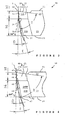
- Figure 4 showing the variant, includes elements 21, 24, 40, 40A, 40B, 41A, 41F, 41 to 44 and 46, 47 counterparts of the elements of figure 3 which have the same unit reference, but with, if applicable, ten "4" which replaces the ten "3". Therefore, the explanation next only relates to a new element, which is a short section 45 of posterior summit edge intended for connect the rear end 44, from the top edge front 43 of the front part 40A, to the section posterior ridge 46 of the posterior part 40B, pedestal.
- the connecting section 45 here concave, overall has a draft angle greater than a draft angle F of the edge section posterior summit 46, itself greater than the angle of previous draft D.
- the posterior summit edge section 46 is thus “quickly" offset back from the cut piece when going from the anterior summit ridge 33 to posterior ridge section 46. Thanks to this "initial" margin of guard in relation to the cut piece, the clearance angle F could alternatively be equal or even less than the anterior draft angle D, in the extent to which the draft angle defined by the ends 44 and 47 of the posterior ridge 45, 46 remains greater than the anterior clearance angle D.
- the section of undercut clearance curve 45 here shows a lateral extension of about 5% of the lateral height value of the front face 41, extension which, in other cases, is preferably between 1 and 50% of the height of tooth 40.
- flanks 41F or branches of the U are folded down, at an angle here reaching almost 90 degrees, for example here around 85 degrees, in overall a direction plane oblique to direction extension of the nose point edge 42, and therefore also relative to the surface to be machined.
- Flanks 41F therefore have a penetration attack component reduced according to the cosine of the fallback angle, by about 85 degrees.
- the penetration thickness is therefore reduced by even, which allows a lower draft, reduced in function of the fallback angle, and for example variant much like the cosine of the fallback angle.
- the area flank 43, 43F has various surfaces, front and lateral, extending substantially in planes respective inclined at bevel angles B (90d - fallback angle) different, with respectively an angle of bevel B equal to 90 degrees for the edge of the beak point 42 and here being 5 degrees for the two flanks 41F, by relative to the direction of penetration perpendicular to a surface of the workpiece.
- the draft angle D of the flank area 43, 43F follows an increasing law as a function the bevel angle B measured relative to the direction normal attack. The law of growth can then substantially represent the sine of the bevel angle B on the attack direction.
- the side profiles are straight.
- they can have a different shape, for example curvilinear or even circular, profile 36, 46 of the rear part 30B, 40B being set back from the virtual extension of the anterior summit ridge 33, 43, defined by a geometric law defining the profile lateral considered.
- the front draft angle D or posterior E to be considered is then the mean angle, or overall, of draft.
- the profiles side of the posterior parts 30B and 40B would be located in a substantially symmetrical position by relative to the plane, vertical in the figures, containing the junction point 34, 44, i.e. heel 37, 47 would form a rostrum, with draft angle E, F negative, extending laterally beyond junction point 34, 44, and preferably beyond the beak point edge 32, 42.
- the dotted lines 36 ', 46' represent thus the rostrum variant position of the profile 36, 46 having turned a certain angle around its connection with the curved section 33, 45.
- the profile 33, 43 of the front part 30A, 40A can likewise have a zero clearance angle D, even negative.
- the insert 10, and in particular the tooth 40 constitutes, from a mechanical point of view, a beam having a lateral profile, in vertical section section right in FIG. 4, such as its moment of inertia I, i.e. the moment or torque of flexural strength manifested by the downward movement of the cutting edge 41A during pruning, grows quadratically in depending on the thickness considered.
- Current thickness can therefore be specified according to a variable which, in figure 5, is the distance X between a current point and a reference point which is the point tip edge 42, going towards the base of tooth 40, that is to say substantially towards hole 11, therefore to the right according to a horizontal in the plane of Figure 4.
- the current moment of inertia I first presents a first segment I1 to growth according to a first law, quadratic, on a first horizontal displacement range ending at straight from the rear end 44 of the summit ridge previous 43.
- the moment of inertia I present a second segment I2, intermediate, with a second law for which growth continues so initially more limited, since the beginning of the curve 45, close to connection point 44, has a slope, thickness growth of the wafer 10, which is less than the slope of the anterior summit ridge 43, relative to the direction of the section plane considered, that is to say a vertical in FIG. 4.
- the second segment of curve I2 remains in below an extrapolation curve of the first segment I1 of moment of inertia curve I.
- the third law corresponds substantially to the first law, with, however, on the one hand, a shift in the value of the distance variable X, due to the presence of the drop associated with the second segment I2, and, on the other share, a weighting (90d - F) of growth quadratic, which is less, because the angle of posterior draft F here is greater than the angle of anterior skin D.
- the start of the third segment I3 is an extension of the end of the second segment because the intermediate section 45 has an end section aligned with the rear edge 46.
- a fourth segment I4 of the moment of inertia curve I corresponds to a horizontal, that is to say a moment of inertia I remaining constant.
- the current cross section When passing through the gorges separating the teeth, the current cross section therefore enters the massive body of insert 10 and a fifth segment I5 of the inertia curve then presents an abrupt rung amount up to a constant level related to the thickness of the plate 10.
- the shapes of moment of inertia curves I above are "basic" curves, corresponding to a fictitious metal slice of tooth 40 which would be cut parallel to the plane of Figure 4, that is to say which would have a constant width (or slice thickness), this width being measured perpendicular to the plane of FIG. 4.
- the width of the tooth 40, perpendicular to the plane of Figure 4 varies according to three parameters.
- the first parameter is the tilt angle of each branch of the U, which the flanks 41F form, by relative to the direction of extension of the point edge of spout 42, itself parallel to the surface of the part machined.
- the cutting edge 41A presents, in top view, front view, branches of U amount diverging slightly, i.e. each folded back for example 85 degrees to the edge of spout 42 at the bottom of the U.
- This first parameter, of widening tooth 40 therefore tends to increase the moment of inertia in flexion, in proportion to this enlargement.
- the second parameter is the draft angle of the flanks 41F, which, descending according to the thickness of the tooth 41A towards the plane of the rear face 24, reduces the width of tooth 40 relative to the width of the cutting edge 41A. This second parameter therefore tends to reduce the moment of inertia I.
- the third parameter is the thickness of the part anterior 40A depending on the variable, i.e. the distance X to the edge of the beak point 42, although this thickness be drawn here as being of value constant.
- connection section 45 can then be modified to present a straight, even curved profile or, better, in S.
- the connecting section 45 has a convex front part with a section front end extending substantially along the direction of the anterior edge 43 at which it connects, and has a rear end portion concave, as drawn, extending substantially along the direction of the associated posterior edge 46. So there is then no discontinuity in the evolution of the value of moment of inertia I at each end of the second segment of curve I2.
- the form of S can be provided for that, between the two end parts above, the I2 moment of inertia curve is substantially rectilinear, thus further limiting any risk of constraint localized.
- a third setting parameter i.e. the current thickness of the part anterior 40A as a function of the distance X to the edge of spout 42, smooths the moment curve of inertia I.
- the determination of the current thickness which suitable for the front part 40A, depending on the desired value of the moment of inertia I, is effected by a inverse transformation of the quadratic law indicated above.
- the width of tooth 40 therefore goes, compared to the "basic" curve described above, grow linearly going, to the right, towards the root of tooth 40.
- the two flanks 40BF of the part 40B also set back from a plane extending the front flanks 41F, also have a draft angle F1, in particular in their area close to the posterior edge 46 to be considered for the third segment I3 of inertia curve.
- the flanks posterior 40BF also contribute to the increase in inertia.
Landscapes
- Engineering & Computer Science (AREA)
- Mechanical Engineering (AREA)
- Cutting Tools, Boring Holders, And Turrets (AREA)
Applications Claiming Priority (2)
| Application Number | Priority Date | Filing Date | Title |
|---|---|---|---|
| FR0215122A FR2847838B1 (fr) | 2002-12-02 | 2002-12-02 | Plaquette de coupe etagee |
| FR0215122 | 2002-12-02 |
Publications (1)
| Publication Number | Publication Date |
|---|---|
| EP1426128A1 true EP1426128A1 (de) | 2004-06-09 |
Family
ID=32309892
Family Applications (1)
| Application Number | Title | Priority Date | Filing Date |
|---|---|---|---|
| EP03292936A Withdrawn EP1426128A1 (de) | 2002-12-02 | 2003-11-26 | Gestufter Schneideinsatz |
Country Status (3)
| Country | Link |
|---|---|
| US (1) | US20040109733A1 (de) |
| EP (1) | EP1426128A1 (de) |
| FR (1) | FR2847838B1 (de) |
Cited By (2)
| Publication number | Priority date | Publication date | Assignee | Title |
|---|---|---|---|---|
| CN102921964A (zh) * | 2012-10-25 | 2013-02-13 | 国家电网公司 | 一种电力设备中聚四氟乙烯绝缘手柄的加工方法 |
| US8827602B2 (en) | 2008-03-10 | 2014-09-09 | Safety | Cutting insert having a chip deflector |
Families Citing this family (12)
| Publication number | Priority date | Publication date | Assignee | Title |
|---|---|---|---|---|
| US7909546B2 (en) * | 2007-03-12 | 2011-03-22 | Mitsubishi Materials Corporation | Thread cutting insert |
| JP5159773B2 (ja) * | 2007-05-28 | 2013-03-13 | 京セラ株式会社 | 切削インサートおよび切削工具並びにそれを用いた切削方法 |
| US20110081210A1 (en) * | 2008-09-29 | 2011-04-07 | Takuya Ishida | Cutting insert, cutting tool and cutting method using the same |
| WO2010110110A1 (ja) * | 2009-03-27 | 2010-09-30 | 京セラ株式会社 | 切削インサート及び切削工具、並びにそれを用いた被削材の切削方法 |
| KR101154704B1 (ko) * | 2010-02-19 | 2012-06-08 | 대구텍 유한회사 | 홈에 의해 분할된 절삭날을 갖는 절삭 인서트 및 이를 구비한 밀링 커터 |
| BR112012031892B8 (pt) * | 2010-06-17 | 2021-03-30 | Tungaloy Corp | inserto de corte para trabalho de formação de roscas |
| CN102091796B (zh) * | 2010-12-23 | 2014-02-05 | 宁波江丰电子材料有限公司 | 一种靶材加工的工具 |
| JP6744599B1 (ja) * | 2019-03-01 | 2020-08-19 | 株式会社タンガロイ | 切削インサート |
| US10974327B1 (en) * | 2019-10-31 | 2021-04-13 | Facet Precision Tool GmbH | Drills and drill bits with buttressed chip breakers |
| CN112518899A (zh) * | 2020-12-21 | 2021-03-19 | 瑞通高分子科技(浙江)有限公司 | 一种五齿循环的带锯条 |
| EP4155018A1 (de) * | 2021-09-22 | 2023-03-29 | Walter Ag | Gewindefräserschneidwerkzeug |
| CN114305748B (zh) * | 2021-12-13 | 2025-06-20 | 无锡时代天使生物科技有限公司 | 加强部添加位置的设计方法、成型方法及存储介质、系统 |
Citations (6)
| Publication number | Priority date | Publication date | Assignee | Title |
|---|---|---|---|---|
| US3754309A (en) * | 1972-01-28 | 1973-08-28 | Kennametal Inc | Cutting insert and clamping arrangement therefor |
| DE3807900A1 (de) * | 1988-03-10 | 1989-09-21 | Link Johann & Ernst Gmbh & Co | An einem halter befestigbare gewindefraesplatte |
| US5755536A (en) * | 1993-06-12 | 1998-05-26 | Walter Ag | indexable cutting insert |
| WO1998033615A1 (en) * | 1997-02-03 | 1998-08-06 | Iscar Ltd. | Cutting inserts |
| US6035744A (en) * | 1997-11-04 | 2000-03-14 | Schwarzkopt Technologies Corp. | Method for the production of a cutting insert for thread cutting |
| US6164878A (en) * | 1996-12-16 | 2000-12-26 | Iscar Ltd. | Cutting inserts |
Family Cites Families (6)
| Publication number | Priority date | Publication date | Assignee | Title |
|---|---|---|---|---|
| DE3639672A1 (de) * | 1986-11-20 | 1988-06-01 | Walter Gmbh Montanwerke | Wendeplattenbestuecktes drehwerkzeug zum einstechen oder gewindeschneiden |
| US4834592A (en) * | 1987-09-04 | 1989-05-30 | Kennametal Inc. | Cutting insert with chip control |
| SE463753B (sv) * | 1989-05-31 | 1991-01-21 | Reinar Schmidt | Utbytbart skaer foer gaengning och spaarstickning |
| US4993893A (en) * | 1990-01-08 | 1991-02-19 | Kennametal Inc. | Cutting insert with chip control |
| US5924825A (en) * | 1998-07-06 | 1999-07-20 | Caterpillar Inc. | Thread cutting insert |
| US6000885A (en) * | 1998-07-22 | 1999-12-14 | Kennametal Inc. | Cutting insert suitable for mounting in different toolholder pockets and associated toolholder assembly |
-
2002
- 2002-12-02 FR FR0215122A patent/FR2847838B1/fr not_active Expired - Fee Related
-
2003
- 2003-11-26 EP EP03292936A patent/EP1426128A1/de not_active Withdrawn
- 2003-12-01 US US10/724,171 patent/US20040109733A1/en not_active Abandoned
Patent Citations (6)
| Publication number | Priority date | Publication date | Assignee | Title |
|---|---|---|---|---|
| US3754309A (en) * | 1972-01-28 | 1973-08-28 | Kennametal Inc | Cutting insert and clamping arrangement therefor |
| DE3807900A1 (de) * | 1988-03-10 | 1989-09-21 | Link Johann & Ernst Gmbh & Co | An einem halter befestigbare gewindefraesplatte |
| US5755536A (en) * | 1993-06-12 | 1998-05-26 | Walter Ag | indexable cutting insert |
| US6164878A (en) * | 1996-12-16 | 2000-12-26 | Iscar Ltd. | Cutting inserts |
| WO1998033615A1 (en) * | 1997-02-03 | 1998-08-06 | Iscar Ltd. | Cutting inserts |
| US6035744A (en) * | 1997-11-04 | 2000-03-14 | Schwarzkopt Technologies Corp. | Method for the production of a cutting insert for thread cutting |
Cited By (2)
| Publication number | Priority date | Publication date | Assignee | Title |
|---|---|---|---|---|
| US8827602B2 (en) | 2008-03-10 | 2014-09-09 | Safety | Cutting insert having a chip deflector |
| CN102921964A (zh) * | 2012-10-25 | 2013-02-13 | 国家电网公司 | 一种电力设备中聚四氟乙烯绝缘手柄的加工方法 |
Also Published As
| Publication number | Publication date |
|---|---|
| FR2847838B1 (fr) | 2006-01-06 |
| US20040109733A1 (en) | 2004-06-10 |
| FR2847838A1 (fr) | 2004-06-04 |
Similar Documents
| Publication | Publication Date | Title |
|---|---|---|
| EP0784454B1 (de) | Einrichtung zur vorläufigen fixierung zweier knochenteile | |
| EP1213980B1 (de) | Vorrichtung zur positionsverriegelung eines bezüglich eines ortsfesten elements beweglichen teils | |
| EP0501860B1 (de) | Schraube, insbesondere Schraubdübel mit hohlem Schaft für weiches Material | |
| WO2000022999A1 (fr) | Plaque d'osteosynthese anterieure pour vertebres lombaires ou lombaire-sacree et instrument pour le positionnement d'une telle plaque | |
| EP2393441A1 (de) | Osteosynthese- und arthrodese-schraube | |
| FR2847838A1 (fr) | Plaquette de coupe etagee | |
| EP0090773B1 (de) | Schneideglied für Sägekette | |
| CA2388371A1 (fr) | Prothese de disque intervertebral a faces dentees | |
| FR2623094A1 (fr) | Dispositif de guidage lateral d'une chaussure de ski fixee, a son extremite avant, sur un ski tel qu'un ski de fond | |
| FR2462958A1 (fr) | Outil de coupe comportant des dents ayant une gorge diviseuse de copeaux | |
| EP3763320A1 (de) | Verbessertes selbstbohrendes zahnimplantat | |
| WO2005089994A1 (fr) | Plaquette de coupe a nombre limite de faces de cadrage | |
| CA2947507A1 (fr) | Lame courbe d'ebranchage, son utilisation, tete d'ebranchage et kit de coupe correspondants | |
| WO2024126938A1 (fr) | Couteau de cuisine | |
| CH688794A5 (fr) | Outil de coupe à plaquettes amovibles. | |
| CH640318A5 (fr) | Vis auto-taraudeuse et procede pour sa fabrication. | |
| FR2878431A1 (fr) | Prothese permettant la correction de l'hallux valgus | |
| EP1475173A1 (de) | Bohrer mit Glättfase | |
| FR2542229A1 (fr) | Porte-outils a plaquettes jetables et plaquettes specifiquement concues pour cooperer avec le porte-outils | |
| FR2789297A1 (fr) | Vis de liaison rehabitable pour l'arthrodese d'une articulation osseuse, notamment pour la stabilisation de deux vertebres | |
| EP1814684A1 (de) | Spitzenfestklemmanordnung | |
| EP4633885B1 (de) | Küchenmesser | |
| FR2864799A1 (fr) | Plaquette de coupe a rame et fraise portant une telle plaquette | |
| FR2864798A1 (fr) | Plaquette de coupe a rampe et fraise portant une telle plaquette | |
| EP1698304A1 (de) | Prothese mit selbststanzenden Erhöhungen |
Legal Events
| Date | Code | Title | Description |
|---|---|---|---|
| PUAI | Public reference made under article 153(3) epc to a published international application that has entered the european phase |
Free format text: ORIGINAL CODE: 0009012 |
|
| AK | Designated contracting states |
Kind code of ref document: A1 Designated state(s): AT BE BG CH CY CZ DE DK EE ES FI FR GB GR HU IE IT LI LU MC NL PT RO SE SI SK TR |
|
| AX | Request for extension of the european patent |
Extension state: AL LT LV MK |
|
| RAP1 | Party data changed (applicant data changed or rights of an application transferred) |
Owner name: SAFETY |
|
| RAP1 | Party data changed (applicant data changed or rights of an application transferred) |
Owner name: SAFETY PRODUCTION |
|
| 17P | Request for examination filed |
Effective date: 20041110 |
|
| AKX | Designation fees paid |
Designated state(s): AT BE BG CH CY CZ DE DK EE ES FI FR GB GR HU IE IT LI LU MC NL PT RO SE SI SK TR |
|
| 17Q | First examination report despatched |
Effective date: 20080819 |
|
| RAP1 | Party data changed (applicant data changed or rights of an application transferred) |
Owner name: SAFETY |
|
| STAA | Information on the status of an ep patent application or granted ep patent |
Free format text: STATUS: THE APPLICATION IS DEEMED TO BE WITHDRAWN |
|
| 18D | Application deemed to be withdrawn |
Effective date: 20090303 |