EP1426163A2 - Tête d'extrusion d'un film tubulaire - Google Patents
Tête d'extrusion d'un film tubulaire Download PDFInfo
- Publication number
- EP1426163A2 EP1426163A2 EP03027609A EP03027609A EP1426163A2 EP 1426163 A2 EP1426163 A2 EP 1426163A2 EP 03027609 A EP03027609 A EP 03027609A EP 03027609 A EP03027609 A EP 03027609A EP 1426163 A2 EP1426163 A2 EP 1426163A2
- Authority
- EP
- European Patent Office
- Prior art keywords
- melt
- tool
- boundary wall
- helix
- outlet nozzle
- Prior art date
- Legal status (The legal status is an assumption and is not a legal conclusion. Google has not performed a legal analysis and makes no representation as to the accuracy of the status listed.)
- Withdrawn
Links
- 239000000155 melt Substances 0.000 claims abstract description 30
- 230000007423 decrease Effects 0.000 claims description 3
- 239000012815 thermoplastic material Substances 0.000 claims description 2
- 238000009826 distribution Methods 0.000 abstract description 7
- 229920001169 thermoplastic Polymers 0.000 abstract description 5
- 239000004416 thermosoftening plastic Substances 0.000 abstract description 4
- 238000001125 extrusion Methods 0.000 description 7
- 239000010410 layer Substances 0.000 description 7
- 238000004519 manufacturing process Methods 0.000 description 5
- 239000002356 single layer Substances 0.000 description 3
- 239000004033 plastic Substances 0.000 description 2
- 238000009827 uniform distribution Methods 0.000 description 2
- 239000002131 composite material Substances 0.000 description 1
- 238000011109 contamination Methods 0.000 description 1
- 238000011161 development Methods 0.000 description 1
- 230000018109 developmental process Effects 0.000 description 1
- 238000009434 installation Methods 0.000 description 1
Images


Classifications
-
- B—PERFORMING OPERATIONS; TRANSPORTING
- B29—WORKING OF PLASTICS; WORKING OF SUBSTANCES IN A PLASTIC STATE IN GENERAL
- B29C—SHAPING OR JOINING OF PLASTICS; SHAPING OF MATERIAL IN A PLASTIC STATE, NOT OTHERWISE PROVIDED FOR; AFTER-TREATMENT OF THE SHAPED PRODUCTS, e.g. REPAIRING
- B29C48/00—Extrusion moulding, i.e. expressing the moulding material through a die or nozzle which imparts the desired form; Apparatus therefor
- B29C48/25—Component parts, details or accessories; Auxiliary operations
- B29C48/36—Means for plasticising or homogenising the moulding material or forcing it through the nozzle or die
- B29C48/50—Details of extruders
- B29C48/695—Flow dividers, e.g. breaker plates
- B29C48/70—Flow dividers, e.g. breaker plates comprising means for dividing, distributing and recombining melt flows
- B29C48/705—Flow dividers, e.g. breaker plates comprising means for dividing, distributing and recombining melt flows in the die zone, e.g. to create flow homogeneity
-
- B—PERFORMING OPERATIONS; TRANSPORTING
- B29—WORKING OF PLASTICS; WORKING OF SUBSTANCES IN A PLASTIC STATE IN GENERAL
- B29C—SHAPING OR JOINING OF PLASTICS; SHAPING OF MATERIAL IN A PLASTIC STATE, NOT OTHERWISE PROVIDED FOR; AFTER-TREATMENT OF THE SHAPED PRODUCTS, e.g. REPAIRING
- B29C48/00—Extrusion moulding, i.e. expressing the moulding material through a die or nozzle which imparts the desired form; Apparatus therefor
- B29C48/03—Extrusion moulding, i.e. expressing the moulding material through a die or nozzle which imparts the desired form; Apparatus therefor characterised by the shape of the extruded material at extrusion
- B29C48/09—Articles with cross-sections having partially or fully enclosed cavities, e.g. pipes or channels
- B29C48/10—Articles with cross-sections having partially or fully enclosed cavities, e.g. pipes or channels flexible, e.g. blown foils
-
- B—PERFORMING OPERATIONS; TRANSPORTING
- B29—WORKING OF PLASTICS; WORKING OF SUBSTANCES IN A PLASTIC STATE IN GENERAL
- B29C—SHAPING OR JOINING OF PLASTICS; SHAPING OF MATERIAL IN A PLASTIC STATE, NOT OTHERWISE PROVIDED FOR; AFTER-TREATMENT OF THE SHAPED PRODUCTS, e.g. REPAIRING
- B29C48/00—Extrusion moulding, i.e. expressing the moulding material through a die or nozzle which imparts the desired form; Apparatus therefor
- B29C48/25—Component parts, details or accessories; Auxiliary operations
- B29C48/30—Extrusion nozzles or dies
- B29C48/3001—Extrusion nozzles or dies characterised by the material or their manufacturing process
-
- B—PERFORMING OPERATIONS; TRANSPORTING
- B29—WORKING OF PLASTICS; WORKING OF SUBSTANCES IN A PLASTIC STATE IN GENERAL
- B29C—SHAPING OR JOINING OF PLASTICS; SHAPING OF MATERIAL IN A PLASTIC STATE, NOT OTHERWISE PROVIDED FOR; AFTER-TREATMENT OF THE SHAPED PRODUCTS, e.g. REPAIRING
- B29C48/00—Extrusion moulding, i.e. expressing the moulding material through a die or nozzle which imparts the desired form; Apparatus therefor
- B29C48/25—Component parts, details or accessories; Auxiliary operations
- B29C48/30—Extrusion nozzles or dies
- B29C48/32—Extrusion nozzles or dies with annular openings, e.g. for forming tubular articles
- B29C48/335—Multiple annular extrusion nozzles in coaxial arrangement, e.g. for making multi-layered tubular articles
-
- B—PERFORMING OPERATIONS; TRANSPORTING
- B29—WORKING OF PLASTICS; WORKING OF SUBSTANCES IN A PLASTIC STATE IN GENERAL
- B29C—SHAPING OR JOINING OF PLASTICS; SHAPING OF MATERIAL IN A PLASTIC STATE, NOT OTHERWISE PROVIDED FOR; AFTER-TREATMENT OF THE SHAPED PRODUCTS, e.g. REPAIRING
- B29C48/00—Extrusion moulding, i.e. expressing the moulding material through a die or nozzle which imparts the desired form; Apparatus therefor
- B29C48/25—Component parts, details or accessories; Auxiliary operations
- B29C48/30—Extrusion nozzles or dies
- B29C48/32—Extrusion nozzles or dies with annular openings, e.g. for forming tubular articles
- B29C48/34—Cross-head annular extrusion nozzles, i.e. for simultaneously receiving moulding material and the preform to be coated
-
- B—PERFORMING OPERATIONS; TRANSPORTING
- B29—WORKING OF PLASTICS; WORKING OF SUBSTANCES IN A PLASTIC STATE IN GENERAL
- B29C—SHAPING OR JOINING OF PLASTICS; SHAPING OF MATERIAL IN A PLASTIC STATE, NOT OTHERWISE PROVIDED FOR; AFTER-TREATMENT OF THE SHAPED PRODUCTS, e.g. REPAIRING
- B29C48/00—Extrusion moulding, i.e. expressing the moulding material through a die or nozzle which imparts the desired form; Apparatus therefor
- B29C48/03—Extrusion moulding, i.e. expressing the moulding material through a die or nozzle which imparts the desired form; Apparatus therefor characterised by the shape of the extruded material at extrusion
- B29C48/09—Articles with cross-sections having partially or fully enclosed cavities, e.g. pipes or channels
-
- B—PERFORMING OPERATIONS; TRANSPORTING
- B29—WORKING OF PLASTICS; WORKING OF SUBSTANCES IN A PLASTIC STATE IN GENERAL
- B29C—SHAPING OR JOINING OF PLASTICS; SHAPING OF MATERIAL IN A PLASTIC STATE, NOT OTHERWISE PROVIDED FOR; AFTER-TREATMENT OF THE SHAPED PRODUCTS, e.g. REPAIRING
- B29C48/00—Extrusion moulding, i.e. expressing the moulding material through a die or nozzle which imparts the desired form; Apparatus therefor
- B29C48/16—Articles comprising two or more components, e.g. co-extruded layers
- B29C48/18—Articles comprising two or more components, e.g. co-extruded layers the components being layers
- B29C48/21—Articles comprising two or more components, e.g. co-extruded layers the components being layers the layers being joined at their surfaces
-
- B—PERFORMING OPERATIONS; TRANSPORTING
- B29—WORKING OF PLASTICS; WORKING OF SUBSTANCES IN A PLASTIC STATE IN GENERAL
- B29C—SHAPING OR JOINING OF PLASTICS; SHAPING OF MATERIAL IN A PLASTIC STATE, NOT OTHERWISE PROVIDED FOR; AFTER-TREATMENT OF THE SHAPED PRODUCTS, e.g. REPAIRING
- B29C48/00—Extrusion moulding, i.e. expressing the moulding material through a die or nozzle which imparts the desired form; Apparatus therefor
- B29C48/25—Component parts, details or accessories; Auxiliary operations
- B29C48/30—Extrusion nozzles or dies
- B29C48/32—Extrusion nozzles or dies with annular openings, e.g. for forming tubular articles
- B29C48/335—Multiple annular extrusion nozzles in coaxial arrangement, e.g. for making multi-layered tubular articles
- B29C48/337—Multiple annular extrusion nozzles in coaxial arrangement, e.g. for making multi-layered tubular articles the components merging at a common location
- B29C48/338—Multiple annular extrusion nozzles in coaxial arrangement, e.g. for making multi-layered tubular articles the components merging at a common location using a die with concentric parts, e.g. rings, cylinders
-
- B—PERFORMING OPERATIONS; TRANSPORTING
- B29—WORKING OF PLASTICS; WORKING OF SUBSTANCES IN A PLASTIC STATE IN GENERAL
- B29L—INDEXING SCHEME ASSOCIATED WITH SUBCLASS B29C, RELATING TO PARTICULAR ARTICLES
- B29L2023/00—Tubular articles
- B29L2023/001—Tubular films, sleeves
Definitions
- the invention relates to a tool for the extrusion of a tubular Melt strand made of thermoplastic with an annular Outlet nozzle and at least one from an associated inlet opening to the Exit nozzle leading and concentric to the central axis of the tool running melt channel, in its boundary wall helical revolving helix forming a downward direction of the melt strand extending spiral distributor are introduced.
- Such a tool is for example from DE 44 07 060 A1 and DE 39 25 042 A1 become known.
- these helices are in the form of helical circumferential grooves usually in the range in relation to the Center axis of the tool inner boundary wall of the melt channel educated. Because of the individual coils composite spiral distributors here essentially in the direction of extrusion and thus extends in the exit direction of the melt strand, which is usually directed vertically from bottom to top, one speaks in this Connection also from a vertical melt distributor.
- the object of the present invention is a tool of the generic type Type with vertical melt distribution with regard to the achievable film quality to improve, especially the previously unavoidable frequent occurrence of film contamination by specks etc. is prevented shall be.
- the invention proposes further training a tool according to the features of protection claim 1 before, at which according to the invention the coil both in the inside Boundary wall as well as in the outer boundary wall of the at least one melt channel are introduced.
- the in the inner boundary wall and in introduced the outer boundary wall of a melt channel The helix is either congruent or in the exit direction staggered, this depends on the respective rheological properties of the thermoplastic to be processed Plastic.
- the depth of the helix starts from the entry opening decreases towards the outlet nozzle.
- the tool according to the invention can be used as a single-layer tool for production a single-layer tubular melt strand z. B. for blown film extrusion be formed, in which case it is only one only melt channel with associated spiral distributor.
- the tool is also provided according to the invention
- Form multi-layer tool there being several to the outlet nozzle leading and concentrically arranged melt channels with the each has associated spiral distributors in which the spiral both in the inside boundary wall as well as in the outside Boundary wall of the respective melt channels are introduced.
- the multilayer tool according to the invention provides that all melt channels are brought together at one point in the mold are and then communicate with the outlet nozzle.
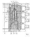
- FIG. 1 shows a tool for extruding a tubular melt strand made of thermoplastic material, for example for the production of Blown films shown in longitudinal section along its central axis A.
- the Tool is designed as a multi-layer tool, here three-layer tool and comprises, in a manner known per se, an inner mandrel 1 which is on the outside from an inner distributor insert 2, leaving a first Melt channel 6.1 is surrounded. On the outside to the inner distributor insert an outer distributor insert 3 is then provided, with between the inner distributor insert 2 and the outer distributor insert 3 a second Melt channel 6.2 is formed. Finally, the outside finish of the tool by an outer jacket 4, wherein between the outer distributor insert 3 and the outer jacket 4, a third melt channel 6.3 remains.
- the melt channels 6.1, 6.2, 6.3 are from the bottom of the tool forth via an inlet 7.1, 7.2, 7.3 with a melt thermoplastic from an extrusion device, not shown fed and the melt channels 6.1, 6.2, 6.3 lead them over the inlet openings 7.1, 7.2, 7.3 melt supplied in the vertical direction upwards to an annular one formed on the top of the tool Exit 5, from which ultimately the entire melt as a tubular Melt strand in an extrusion or exit direction E in itself known way emerges.
- melt channels 6.1, 6.2, 6.3 are just like the ones that limit them Parts of the tool, namely inner mandrel 1, inner distributor insert 2, outer Distribution insert 3 and outer jacket 4 concentric to that in the vertical direction arranged central axis A of the tool.
- melt channels 6.1, 6.2, 6.3 each a layer of subsequently emerging from the tubular outlet nozzle 5 multilayer Lead melt strand, together at a point S within of the tool merged and into a multilayer Melt strand, which then emerges from the annular outlet nozzle 5 in Exit direction E exits.
- the merging of all melt channels 6.1, 6.2, 6.3 at a point S in the tool enables a high thickness consistency the multilayer film obtained.
- bringing the individual together as closely as possible Melt channels 6.1, 6.2, 6.3 successively in the exit direction E. be made to the ideal of merging the melt channels 6.1, 6.2, 6.3 at a point S, as shown in Figure 2, if possible come close.
- the melt flows initially entering via the inlet openings 7.1, 7.2, 7.3 in each case one extending in the exit direction of the melt strand Spiral distributor 8 open, in which the melt starting from the Entry opening as evenly as possible over the entire circumference of the respective melt channel 6.1, 6.2, 6.3 is distributed to a uniform To obtain layer thickness over the entire outlet gap of the outlet nozzle 5.
- melt channel is an example 6.1 can be seen in which the entering from the inlet 7.1 Melt is conveyed in the direction of the annular outlet nozzle 5.
- the Melt channel 6.1 is in relation to the central axis A on the inside of an inside boundary wall 60 and outside of one outside boundary wall 61 limited.
- the following based on the The melt channel 6.1 explanations apply analogously to the other melt channels 6.2 and 6.3.
- the spiral distributor 8 is of helical shape about the central axis A of the Tool revolving and into the boundary walls of the melt channel 6.1 introduced groove-shaped spirals 80a, 80b formed one Distribute the melt around the circumference of the melt channel.
- spiral distributor 8 An essential feature of the spiral distributor 8 is that the Spiral distributor 8 forming helical circumferential spiral 80a, 80b both in the inner boundary wall 60 and in the introduced outside boundary wall 61 of the melt channel 6 are, whereby the distribution of the melt in the melt channel 6 is significant can improve and also the deposit of specks and the like, which subsequently contaminate the emerging tubular Lead melt strand, is counteracted.
- the inside and externally introduced helix can be the same or rotate in opposite directions around the central axis A.
- these are in the inside Boundary wall 60 formed spiral 80a and that in the outside boundary wall 61 formed helix 80b congruent arranged opposite each other.
- helix 80a also compared to that in the outside wall 61 introduced helix 80b arranged offset to one another in the exit direction E. become.
- the filaments 80a, 80b preferably have a cross section considered, d. H. for example, within the drawing plane, a semicircular Shape, furthermore their depth T, which simultaneously the Radius of the helix 80a, 80b forms, starting from the inlet opening 7.1, 7.2, 7.3 be designed to decrease in the direction of the annular outlet nozzle 5 can.
- FIG. 5 shows that in addition to the coils marked with reference number 80 with semicircular Cross-section also provided such cross-sectional shapes for helix can be, whose outline is approximated to an ellipse, what with Reference numeral 80.1 is shown. Other suitable cross-sectional shapes the helix can be selected.
- the tool can also more or less melt channels than the three melt channels shown here 6.1, 6.2, 6.3 have, for example, as a single-layer tool with only one melt channel or as a multi-layer tool with two or more melt channels can be formed.
Landscapes
- Engineering & Computer Science (AREA)
- Mechanical Engineering (AREA)
- Manufacturing & Machinery (AREA)
- Extrusion Moulding Of Plastics Or The Like (AREA)
Applications Claiming Priority (4)
| Application Number | Priority Date | Filing Date | Title |
|---|---|---|---|
| DE20218760 | 2002-12-04 | ||
| DE20218760U | 2002-12-04 | ||
| DE20307412U DE20307412U1 (de) | 2002-12-04 | 2003-05-13 | Werkzeug zur Extrusion eines rohrförmigen Schmelzestranges |
| DE20307412U | 2003-05-13 |
Publications (1)
| Publication Number | Publication Date |
|---|---|
| EP1426163A2 true EP1426163A2 (fr) | 2004-06-09 |
Family
ID=32313750
Family Applications (1)
| Application Number | Title | Priority Date | Filing Date |
|---|---|---|---|
| EP03027609A Withdrawn EP1426163A2 (fr) | 2002-12-04 | 2003-12-02 | Tête d'extrusion d'un film tubulaire |
Country Status (2)
| Country | Link |
|---|---|
| US (1) | US20040166192A1 (fr) |
| EP (1) | EP1426163A2 (fr) |
Cited By (1)
| Publication number | Priority date | Publication date | Assignee | Title |
|---|---|---|---|---|
| WO2013113305A1 (fr) | 2012-01-30 | 2013-08-08 | Reifenhäuser GmbH & Co. KG Maschinenfabrik | Distributeur hélicoïdal, tête de soufflage, installation de film de soufflage, procédé de fabrication d'un film de soufflage et film de soufflage |
Families Citing this family (7)
| Publication number | Priority date | Publication date | Assignee | Title |
|---|---|---|---|---|
| DE102004040151B4 (de) * | 2004-08-19 | 2008-08-21 | Hosokawa Alpine Ag | Folienblaskopf für die Herstellung von Schlauchfolien |
| DE102007029310A1 (de) * | 2007-02-13 | 2008-08-14 | Kiefel Extrusion Gmbh | Wendelverteiler für eine Blasfolienanlage |
| WO2009000509A2 (fr) * | 2007-06-28 | 2008-12-31 | Reifenhäuser GmbH & Co. KG Maschinenfabrik | Dispositif de réalisation de films de soufflage |
| DE102008010796A1 (de) * | 2007-10-18 | 2009-04-23 | Reifenhäuser GmbH & Co. KG Maschinenfabrik | Verfahren und Vorrichtung zur kontinuierlichen Herstellung eines Extrudats aus feinteiligem Pflanzenmaterial und einem thermoplastischen Material |
| EP2298678B1 (fr) * | 2009-09-18 | 2012-02-22 | Reifenhäuser GmbH & Co. Maschinenfabrik | Dispositif d'enroulement |
| WO2013149176A1 (fr) | 2012-03-29 | 2013-10-03 | Gloucester Engineering Co., Inc. | Configuration de rainure en spirale de filière annulaire |
| EP3216583B1 (fr) | 2016-03-11 | 2021-04-28 | Reifenhäuser GmbH & Co. KG Maschinenfabrik | Adaptateur de coextrusion |
Family Cites Families (16)
| Publication number | Priority date | Publication date | Assignee | Title |
|---|---|---|---|---|
| US3809515A (en) * | 1972-03-03 | 1974-05-07 | Farrell Patent Co | Extrusion die for blowing plastic film |
| US4185954A (en) * | 1977-08-23 | 1980-01-29 | Kabushiki Kaisha Plastic Kogaku Kenkyusho | Die for extruding tubes composed of a plurality of layers |
| US4182603A (en) * | 1978-03-27 | 1980-01-08 | Egan Machinery Company | Multilayer tubular extrusion die |
| JP2674185B2 (ja) * | 1989-02-28 | 1997-11-12 | 三菱樹脂株式会社 | 多層環状口金 |
| SE500794C2 (sv) * | 1989-06-09 | 1994-09-05 | Marie Irene Susanne Iacconi | Extrudermunstycke med rullningslager |
| US5256049A (en) * | 1990-06-01 | 1993-10-26 | Mauser-Werke Gmbh | Storage head for a blow molding machine |
| US5648104A (en) * | 1991-01-17 | 1997-07-15 | The University Of Manchester Institute Of Science And Technology | Extrusion die |
| CA2082437C (fr) * | 1991-11-14 | 1998-01-20 | Peter C. Gates | Filiere d'extrusion de produits tubulaires multicouches a alimentation en spirale |
| US5843490A (en) * | 1994-07-15 | 1998-12-01 | Tosoh Corporation | Die having protrusions for molding machine |
| JP3471924B2 (ja) * | 1994-09-21 | 2003-12-02 | 呉羽化学工業株式会社 | スパイラルダイおよびこれを用いる積層体製造方法 |
| WO1996033856A1 (fr) * | 1995-04-24 | 1996-10-31 | Black Clawson Sano Inc. | Matrice a extrusion |
| US6073657A (en) * | 1995-12-12 | 2000-06-13 | Uponor Innovation Ab | Method for producing homogeneous material with an extruder, an extruder, and a multilayer plastic pipe |
| CA2191630A1 (fr) * | 1995-12-14 | 1997-06-15 | Surendra M. Sagar | Filiere annulaire de co-extrusion |
| US5690972A (en) * | 1996-07-01 | 1997-11-25 | Macro Engineering & Technology Inc. | Annular co-extrusion die |
| FI103024B1 (fi) * | 1997-09-01 | 1999-04-15 | Conenor Oy | Menetelmä ja laite jätemateriaalin käsittelemiseksi |
| CZ296646B6 (cs) * | 1999-04-16 | 2006-05-17 | Mauser-Werke Gmbh | Vytlacovací hlava |
-
2003
- 2003-12-02 EP EP03027609A patent/EP1426163A2/fr not_active Withdrawn
- 2003-12-03 US US10/727,146 patent/US20040166192A1/en not_active Abandoned
Cited By (2)
| Publication number | Priority date | Publication date | Assignee | Title |
|---|---|---|---|---|
| WO2013113305A1 (fr) | 2012-01-30 | 2013-08-08 | Reifenhäuser GmbH & Co. KG Maschinenfabrik | Distributeur hélicoïdal, tête de soufflage, installation de film de soufflage, procédé de fabrication d'un film de soufflage et film de soufflage |
| DE112013000756B4 (de) * | 2012-01-30 | 2025-02-27 | Reifenhäuser GmbH & Co. KG Maschinenfabrik | Wendelverteiler, Blaskopf, Blasfolienanlage, Verfahren zum Herstellen einer Blasfolie |
Also Published As
| Publication number | Publication date |
|---|---|
| US20040166192A1 (en) | 2004-08-26 |
Similar Documents
| Publication | Publication Date | Title |
|---|---|---|
| DE19781849B4 (de) | Ringförmige, konzentrische Extruderdüse | |
| EP0431681B1 (fr) | Procédé et outil d'extrusion pour la fabrication d'une ébauche pourvue d'alésages internes | |
| EP0486636B1 (fr) | Tete d'accumulation pour machines de moulage par soufflage | |
| DE2537419C2 (de) | Schmelzeverteiler in Rohr- oder Blasköpfen mit einer Pinole als Kern und diese umgebenden Gehäuse | |
| DE69424444T2 (de) | Hochfeste seele für drahtseile | |
| DE4120165A1 (de) | Strangpresswerkzeug zur herstellung eines hartmetall- oder keramikstabes | |
| DE69319835T2 (de) | Vorrichtung und Verfahren zum Herstellen eines mehrschichtiges Laminatfilms | |
| DE19535749C1 (de) | Extrusionskopf zur Herstellung von schlauch- oder rohrförmigen Vorformlingen aus extrudierbarem Kunststoff | |
| DE3011425A1 (de) | Verfahren und vorrichtung zum herstellen von kunststoffrohren mit laengslaufenden hohlkanaelen in deren wandung | |
| EP3266586A1 (fr) | Outil multicouches | |
| EP1784297B1 (fr) | Tete de soufflage de films pour la production de films tubulaires | |
| DE3902270A1 (de) | Verfahren und vorrichtung zur diskontinuierlichen herstellung mehrschichtiger, coextrudierter, schlauchartiger vorformlinge aus thermoplastischem kunststoff | |
| DE20307412U1 (de) | Werkzeug zur Extrusion eines rohrförmigen Schmelzestranges | |
| EP1055504A1 (fr) | Filière d'extrusion | |
| EP2332714A1 (fr) | Adaptateur de coextrusion | |
| DE2333488A1 (de) | Einstueckiger schlauch und einrichtung und verfahren zu seiner herstellung | |
| EP1958756A1 (fr) | Distributeur réversible hélicoïdal ou axial pour une installation de feuilles de soufflage ainsi que procédé de fabrication d'une feuille multicouches | |
| DE2554239A1 (de) | Verfahren und vorrichtung zum ummanteln eines extrudierten kernprofiles aus kunststoff | |
| DE3026822A1 (de) | Vorrichtung zum herstellen eines schlauchfoermigen stranges aus thermoplastischem kunststoff | |
| DE20220574U1 (de) | Vorrichtung zur Herstellung von Kunststoffrohren | |
| DE69708651T2 (de) | Extrusionsvorrichtung und verfahren | |
| DE4109369C2 (fr) | ||
| EP0275057B1 (fr) | Dispositif d' extrusion d' un profile avec un effet de marbre | |
| EP3479993B1 (fr) | Distributeur annulaire pour une tête d'extrusion permettant de fabriquer une pièce moulée en forme tubulaire en matière thermoplastique | |
| DE4339671C2 (de) | Vorrichtung zum Herstellen eines schlauch- oder rohrförmigen Hohlstranges aus thermoplastischem Kunststoff |
Legal Events
| Date | Code | Title | Description |
|---|---|---|---|
| PUAI | Public reference made under article 153(3) epc to a published international application that has entered the european phase |
Free format text: ORIGINAL CODE: 0009012 |
|
| AK | Designated contracting states |
Kind code of ref document: A2 Designated state(s): AT BE BG CH CY CZ DE DK EE ES FI FR GB GR HU IE IT LI LU MC NL PT RO SE SI SK TR |
|
| AX | Request for extension of the european patent |
Extension state: AL LT LV MK |
|
| STAA | Information on the status of an ep patent application or granted ep patent |
Free format text: STATUS: THE APPLICATION IS DEEMED TO BE WITHDRAWN |
|
| 18D | Application deemed to be withdrawn |
Effective date: 20070703 |