EP1426227A2 - Einbauvorrichtung einer Rückholfeder für einen Schalthebel eines Kraftfahrzeuges - Google Patents
Einbauvorrichtung einer Rückholfeder für einen Schalthebel eines Kraftfahrzeuges Download PDFInfo
- Publication number
- EP1426227A2 EP1426227A2 EP03356176A EP03356176A EP1426227A2 EP 1426227 A2 EP1426227 A2 EP 1426227A2 EP 03356176 A EP03356176 A EP 03356176A EP 03356176 A EP03356176 A EP 03356176A EP 1426227 A2 EP1426227 A2 EP 1426227A2
- Authority
- EP
- European Patent Office
- Prior art keywords
- pivot
- lever
- return spring
- light
- spring
- Prior art date
- Legal status (The legal status is an assumption and is not a legal conclusion. Google has not performed a legal analysis and makes no representation as to the accuracy of the status listed.)
- Granted
Links
- 230000000295 complement effect Effects 0.000 claims abstract description 14
- 238000006073 displacement reaction Methods 0.000 claims description 11
- 230000000694 effects Effects 0.000 claims description 7
- 230000000903 blocking effect Effects 0.000 claims description 6
- 238000000034 method Methods 0.000 description 8
- 230000007935 neutral effect Effects 0.000 description 4
- 230000001747 exhibiting effect Effects 0.000 description 1
Images


Classifications
-
- F—MECHANICAL ENGINEERING; LIGHTING; HEATING; WEAPONS; BLASTING
- F16—ENGINEERING ELEMENTS AND UNITS; GENERAL MEASURES FOR PRODUCING AND MAINTAINING EFFECTIVE FUNCTIONING OF MACHINES OR INSTALLATIONS; THERMAL INSULATION IN GENERAL
- F16H—GEARING
- F16H59/00—Control inputs to control units of change-speed- or reversing-gearings for conveying rotary motion
- F16H59/02—Selector apparatus
- F16H59/04—Ratio selector apparatus
-
- F—MECHANICAL ENGINEERING; LIGHTING; HEATING; WEAPONS; BLASTING
- F16—ENGINEERING ELEMENTS AND UNITS; GENERAL MEASURES FOR PRODUCING AND MAINTAINING EFFECTIVE FUNCTIONING OF MACHINES OR INSTALLATIONS; THERMAL INSULATION IN GENERAL
- F16H—GEARING
- F16H57/00—General details of gearing
- F16H2057/0056—Mounting parts arranged in special position or by special sequence, e.g. for keeping particular parts in his position during assembly
-
- F—MECHANICAL ENGINEERING; LIGHTING; HEATING; WEAPONS; BLASTING
- F16—ENGINEERING ELEMENTS AND UNITS; GENERAL MEASURES FOR PRODUCING AND MAINTAINING EFFECTIVE FUNCTIONING OF MACHINES OR INSTALLATIONS; THERMAL INSULATION IN GENERAL
- F16H—GEARING
- F16H59/00—Control inputs to control units of change-speed- or reversing-gearings for conveying rotary motion
- F16H59/02—Selector apparatus
- F16H2059/0295—Selector apparatus with mechanisms to return lever to neutral or datum position, e.g. by return springs
-
- F—MECHANICAL ENGINEERING; LIGHTING; HEATING; WEAPONS; BLASTING
- F16—ENGINEERING ELEMENTS AND UNITS; GENERAL MEASURES FOR PRODUCING AND MAINTAINING EFFECTIVE FUNCTIONING OF MACHINES OR INSTALLATIONS; THERMAL INSULATION IN GENERAL
- F16H—GEARING
- F16H59/00—Control inputs to control units of change-speed- or reversing-gearings for conveying rotary motion
- F16H59/02—Selector apparatus
- F16H59/0278—Constructional features of the selector lever, e.g. grip parts, mounting or manufacturing
Definitions
- the invention relates to the technical sector of equipment for motor vehicles and more particularly to the selection command gearboxes, especially mechanical.
- the selection and shifting control is effected by means of a lever mounted with angular displacement capacity in a housing support generally fixed at the level of the cabin of the motor vehicle.
- the lower end of the lever has arrangements to ensure, in combination with generally returning members, the selection and shifting.
- the return and selection element which is attached to the control lever, is mounted with articulation capability with respect to an axis.
- the axis is equipped with a member adapted to ensure the recall of the selection element.
- this return member is constituted by a pin spring mounted in a prestressed manner about the axis.
- the branches of the spring are biased separately, under a pivoting effect of the lever, by a lug integral with the selection element cooperating with a fixed stop element.
- the pivot axis, the lug and the end of the articulation of the lever constitute three aligned points of reference. It is the same when the selection is made by a finger integral with a portion of the lever.
- the return spring is mounted on a pivot.
- the gearbox is in neutral, it is necessary that the order is also delivered in neutral.
- a blocking element known as the "method tool” whose purpose is to temporarily remove the lever selection function.
- the aim is to obtain the best possible synchronization between the dead point of the control lever and the gearbox. This result is obtained by a length adjustment in particular of the selection cable, but also by the alignment of the three points mentioned above.
- the use of the method tool necessary to temporarily remove the selection, generates a constraint at one of the branches of the return spring.
- the method tool tends to constrain the spring and, concomitantly, cause the angular displacement of the selection element and consequently the misalignment of the three points. It can therefore result in a bad synchronism in the lever control of the gearbox.
- the aim of the invention is to remedy these drawbacks, simple, safe, effective and rational way.
- the problem to be solved by the invention is to ensure the synchronization of the method tool with, in particular, the spring of selection so as not to subject the latter to a constraint likely to generate a misalignment of the different reference points.
- the return spring is secured to an element mounted in a support part with displacement capacity in guided translation under the effect of a force exerted on a part of the return spring, to allow a self-alignment of the element with a fixed point and a movable point corresponding to the movement of the lever so as not to pre-constrain the spring, said element and said part having complementary arrangements capable of ensuring the locking in translation of the element after its self- alignment.
- the element is a pivot that has a head for mounting the return spring and a centering surface capable of being engaged in a emergent lumen formed in the thickness of the support portion.
- the range of centering has two distinct zones, namely a suitable end zone to be freely engaged in the light with sliding ability guided, and an area exhibiting blocking arrangements able to cooperate with the complementary arrangements that said light.
- the complementary blocking arrangements are constituted by a system of complementary teeth.
- the two zones are arranged one above the other in being separated and delimited by clipping profiles to allow, in first, under a partial depression of the pivot, the positioning of the end zone in the light in view of the free displacement in translation, then, in a second step, after depression of the entire pivot, the interlocking of the teeth of the other area with the teeth of said light.
- the centering surface is split according to its generators to be deformable by elasticity.
- the latter has a complementary cross-section of that of light to ensure its angular indexing.
- the spring has two branches cooperating with the fixed point and the moving point and able to constrain one or the other said branches under an effect of angular displacement of the lever.
- the support part is relative to a housing receiving the control lever, or the support part is relative to the body of selection.
- Figure 1 shows an example of housing (B) gearbox receiving, with articulation capacity, a control lever (L) for the passage and selection of speeds by means of cables (C1) and (C2).
- the selection of the speeds, by acting on the lever (L) can be carried out either through a referral and selection element coupled to the lever and the cable (C2), which, as is the case examples of the figures of the drawings, by a selection finger (D) integral, for example, the ball joint (R) of the lever relative to the housing (B).
- Lever back in position, for speed selection is effected by means of a spring (1). It is recalled that after setting the gearbox in relation to the neutral position (at the control and of the gearbox), the return spring (1) cooperates with the two points fixed (P1) and (P2) and a moving point (P3) corresponding to the displacement angle of the lever foot (L) during its maneuver.
- the return spring (1) is subjected to at least one element (2) mounted with displacement capacity in guided translation under the effect of a force exerted on a part of that jurisdiction, in particular during the implementation of the method tool (0) ( Figure 1).
- the ability to displacement in translation allows a self-alignment of the element (2) with the fixed points (P1) - (P2), and the moving point (P3), so as not to force the spring (1).
- item (2) and the party receiving it present complementary arrangements capable of ensuring its locking in translation after self-alignment.
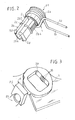
- the element (which constitutes the fixed point (P1)) is constituted by an axis or pivot (2) which has a head (2a) for mounting the return spring (1) which is wound around said head (2a) allowing the crossing and overflow of two rectilinear and parallel branches (1a) and (1b).
- the head (2a) is extended by a centering surface (2b) adapted to be engaged in a through opening (3a) formed in the thickness, either of a return and selection element, or of a part (3). ) of the housing (B).
- This centering span (2b) has two distinct zones (2b1) and (2b2).
- the entire centering bearing (2b) is split along its generatrices (2b3) to be deformable by elasticity.
- the end zone (2b1) is shaped to be freely engaged in the light (3a) of the portion (3) with guided sliding capacity.
- the other zone (2b2) has blocking arrangements (2b4) capable of cooperating with complementary arrangements (3b) that have the parallel and opposite rectilinear parts of the light (3a).
- the two zones (2b1) and (2b2) are separated by a clipping profile (2c).
- the free end of the zone (2b1) is terminated by a clipping profile (2d).
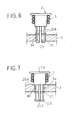
- the two zones (2b1) and (2b2) are arranged one above the other to allow, at first, under a partial depression of the pivot (2), the positioning of the end zone (2b1), by clipping, in the light (3a), abutting against the clipping profile (2c).
- the pivot axis (2) can be moved in translation ( Figure 4).
- the portion (2b2) of the span (2b) is located in the light (3a), in the nesting position of the teeth complementary (2b4) (3b). This position corresponds to a blockage in translation of the axis (2) ( Figure 5).
- the point (P1) is constituted by the pivot (2), the fixed point (P2) by a stop (4), solidaire for example of a portion of the housing, and the movable point (P3) by the end of the hinge lever (L), or the selection finger (D).
- the pivot (2) is engaged in the light (3a) by the end (2b1).
- the two branches (1a) and (1b) of the return spring (1) are arranged in support, on both sides of the fixed stop element (4), and the finger of selection (D).
- the implementation of the method tool (O) on the lever (L) to temporarily block the selection may create a constraint to the level including one of the branches (1a) or (1b) of the spring (1) causing, concomitantly, displacement in translation limited pivot (2) and, therefore, the self-alignment of the points (P1), (P2) and (P3) ( Figures 4 and 6).
Landscapes
- Engineering & Computer Science (AREA)
- General Engineering & Computer Science (AREA)
- Mechanical Engineering (AREA)
- Arrangement Or Mounting Of Control Devices For Change-Speed Gearing (AREA)
- Gear-Shifting Mechanisms (AREA)
- Mechanical Control Devices (AREA)
Priority Applications (1)
| Application Number | Priority Date | Filing Date | Title |
|---|---|---|---|
| SI200330853T SI1426227T1 (sl) | 2002-12-03 | 2003-11-14 | Vgradna priprava povratne vzmeti za stikalno ročico motornega vozila |
Applications Claiming Priority (2)
| Application Number | Priority Date | Filing Date | Title |
|---|---|---|---|
| FR0215397A FR2847877B1 (fr) | 2002-12-03 | 2002-12-03 | Dispositif de montage d'un ressort de rappel d'un organe de selection accouple a un levier de commande d'une boite de vitesse pour vehicules automobiles |
| FR0215397 | 2002-12-03 |
Publications (3)
| Publication Number | Publication Date |
|---|---|
| EP1426227A2 true EP1426227A2 (de) | 2004-06-09 |
| EP1426227A3 EP1426227A3 (de) | 2006-05-31 |
| EP1426227B1 EP1426227B1 (de) | 2007-03-28 |
Family
ID=32310020
Family Applications (1)
| Application Number | Title | Priority Date | Filing Date |
|---|---|---|---|
| EP03356176A Expired - Lifetime EP1426227B1 (de) | 2002-12-03 | 2003-11-14 | Einbauvorrichtung einer Rückholfeder für einen Schalthebel eines Kraftfahrzeuges |
Country Status (6)
| Country | Link |
|---|---|
| EP (1) | EP1426227B1 (de) |
| AT (1) | ATE358034T1 (de) |
| DE (1) | DE60312800T2 (de) |
| ES (1) | ES2285072T3 (de) |
| FR (1) | FR2847877B1 (de) |
| SI (1) | SI1426227T1 (de) |
Cited By (1)
| Publication number | Priority date | Publication date | Assignee | Title |
|---|---|---|---|---|
| FR2927573A1 (fr) * | 2008-02-19 | 2009-08-21 | Renault Sas | Boitier de commande externe d'une boite de vitesses d'un vehicule automobile |
Families Citing this family (2)
| Publication number | Priority date | Publication date | Assignee | Title |
|---|---|---|---|---|
| FR2893549B1 (fr) * | 2005-11-24 | 2008-02-15 | Dura Automotive Systems Soc Pa | Ensemble support pour levier de commande d'une boite de vitesses mecaniques de vehicules automobiles |
| FR2922982B1 (fr) | 2007-10-31 | 2009-11-13 | Dura Automotive Systems Sas | Dispositif pour synchroniser, au point mort, un levier de commande d'une boite de vitesse avec la commande interne de ladite boite de vitesses d'un vehicule automobile. |
Family Cites Families (2)
| Publication number | Priority date | Publication date | Assignee | Title |
|---|---|---|---|---|
| US4458549A (en) * | 1981-08-12 | 1984-07-10 | Toyota Jidosha Kogyo Kabushiki Kaisha | Select return mechanism for a transmission |
| JPS60134922A (ja) * | 1983-12-24 | 1985-07-18 | Toyota Motor Corp | 変速操作機構のセレクトリタ−ン装置 |
-
2002
- 2002-12-03 FR FR0215397A patent/FR2847877B1/fr not_active Expired - Lifetime
-
2003
- 2003-11-14 DE DE60312800T patent/DE60312800T2/de not_active Expired - Lifetime
- 2003-11-14 SI SI200330853T patent/SI1426227T1/sl unknown
- 2003-11-14 EP EP03356176A patent/EP1426227B1/de not_active Expired - Lifetime
- 2003-11-14 AT AT03356176T patent/ATE358034T1/de not_active IP Right Cessation
- 2003-11-14 ES ES03356176T patent/ES2285072T3/es not_active Expired - Lifetime
Cited By (1)
| Publication number | Priority date | Publication date | Assignee | Title |
|---|---|---|---|---|
| FR2927573A1 (fr) * | 2008-02-19 | 2009-08-21 | Renault Sas | Boitier de commande externe d'une boite de vitesses d'un vehicule automobile |
Also Published As
| Publication number | Publication date |
|---|---|
| FR2847877B1 (fr) | 2005-02-11 |
| EP1426227A3 (de) | 2006-05-31 |
| DE60312800T2 (de) | 2007-12-06 |
| EP1426227B1 (de) | 2007-03-28 |
| FR2847877A1 (fr) | 2004-06-04 |
| SI1426227T1 (sl) | 2007-12-31 |
| DE60312800D1 (de) | 2007-05-10 |
| ES2285072T3 (es) | 2007-11-16 |
| ATE358034T1 (de) | 2007-04-15 |
Similar Documents
| Publication | Publication Date | Title |
|---|---|---|
| EP0805078B1 (de) | Angetriebene Verriegelungsvorrichtung für Fahrzeuge mit verbesserten Mitteln zur Begrenzung der Bewegung eines Riegels | |
| WO2007132133A1 (fr) | Système de verrouillage d'un premier arbre par rapport à un deuxième arbre supprimant les jeux entre lesdits arbres | |
| EP2751437A1 (de) | Vorrichtung zum verbinden einer lenksäule mit einem lenkgetriebegehäuse | |
| EP1207255A2 (de) | Mechanisches Modul für einen Schlüssel, Schlüssel mit einem solchen Modul und Verfahren zur Befestigung eines solchen Moduls an einem Schlüssel | |
| FR2673448A1 (fr) | Connecteur pour cable dans un dispositif formant verrou de la direction. | |
| EP0703395B1 (de) | System zur axialen Festlegung eines langgestreckten Elements | |
| FR3123880A1 (fr) | Palier de guidage d’une crémaillère d’un système de direction | |
| EP1426227B1 (de) | Einbauvorrichtung einer Rückholfeder für einen Schalthebel eines Kraftfahrzeuges | |
| FR2538754A1 (fr) | Dispositif pour l'assemblage detachable d'elements de rails preneurs dans une presse-transfert | |
| FR2775226A1 (fr) | Dispositif de reglage de la course de selection d'un levier de vitesse de vehicule automobile entre le point mort et le couloir de vitesses 1-2 | |
| EP0859158A1 (de) | Vorrichtung zum Verbinden das Endstück einen Bowdenzug auf einem Kugelgelenk, und Anwendung zu der Schaltvorrichtung für ein Zahnräderwechselgetriebe | |
| EP1790878B1 (de) | Befestigungsanordnung für einen Schalthebel eines Kraftfahrzeughandschaltgetriebes | |
| EP0597764A1 (de) | Fensterheber für ein Kraftfahrzeug | |
| EP1300535B1 (de) | Einstellbarer Anschlag für bewegliche Teile einer Fahrzeugkarosserie | |
| EP1293371B1 (de) | Verbindungsanordnung und entsprechendes Kraftfahrzeug | |
| FR2649027A1 (fr) | Porte-outil de machine-outil associe a un dispositif de connexions automatiques | |
| EP0192531A1 (de) | Lager, insbesondere für Zahnstangenlenkung | |
| EP1757829B1 (de) | Vorrichtung zur Erzeugung eines vordefinierten Spannungszustands bei Bedienungsvorrichtung mit einem in eine Führungshülle eingelegten Kabel | |
| WO2024023255A1 (fr) | Dispositif d'obturation | |
| EP1908967A1 (de) | Vorrichtung zum Befestigen eines Kabels auf einer Halteplatine | |
| EP2055995A1 (de) | Vorrichtung zum Kalibrieren eines Schalthebels in Neutralstellung mit der Schaltvorrichtung in einem Kraftfahrzeuggetriebe | |
| EP4491912A1 (de) | Parksperren-entriegelungsvorrichtung für ein automatisches getriebe | |
| FR2594761A1 (fr) | Dispositif de fixation reglable, notamment pour projecteur de vehicule automobile | |
| EP0511088A2 (de) | Vorrichtung zur automatischen Längenverstellung eines Bowdenzuges | |
| EP0722877A1 (de) | Vorrichtung zur Befestigung einer Lenksäule, insbesondere eines Kraftfahrzeugs |
Legal Events
| Date | Code | Title | Description |
|---|---|---|---|
| PUAI | Public reference made under article 153(3) epc to a published international application that has entered the european phase |
Free format text: ORIGINAL CODE: 0009012 |
|
| AK | Designated contracting states |
Kind code of ref document: A2 Designated state(s): AT BE BG CH CY CZ DE DK EE ES FI FR GB GR HU IE IT LI LU MC NL PT RO SE SI SK TR |
|
| AX | Request for extension of the european patent |
Extension state: AL LT LV MK |
|
| PUAL | Search report despatched |
Free format text: ORIGINAL CODE: 0009013 |
|
| AK | Designated contracting states |
Kind code of ref document: A3 Designated state(s): AT BE BG CH CY CZ DE DK EE ES FI FR GB GR HU IE IT LI LU MC NL PT RO SE SI SK TR |
|
| AX | Request for extension of the european patent |
Extension state: AL LT LV MK |
|
| 17P | Request for examination filed |
Effective date: 20060616 |
|
| GRAP | Despatch of communication of intention to grant a patent |
Free format text: ORIGINAL CODE: EPIDOSNIGR1 |
|
| AKX | Designation fees paid |
Designated state(s): AT BE BG CH CY CZ DE DK EE ES FI FR GB GR HU IE IT LI LU MC NL PT RO SE SI SK TR |
|
| GRAS | Grant fee paid |
Free format text: ORIGINAL CODE: EPIDOSNIGR3 |
|
| GRAA | (expected) grant |
Free format text: ORIGINAL CODE: 0009210 |
|
| AK | Designated contracting states |
Kind code of ref document: B1 Designated state(s): AT BE BG CH CY CZ DE DK EE ES FI FR GB GR HU IE IT LI LU MC NL PT RO SE SI SK TR |
|
| PG25 | Lapsed in a contracting state [announced via postgrant information from national office to epo] |
Ref country code: NL Free format text: LAPSE BECAUSE OF FAILURE TO SUBMIT A TRANSLATION OF THE DESCRIPTION OR TO PAY THE FEE WITHIN THE PRESCRIBED TIME-LIMIT Effective date: 20070328 Ref country code: FI Free format text: LAPSE BECAUSE OF FAILURE TO SUBMIT A TRANSLATION OF THE DESCRIPTION OR TO PAY THE FEE WITHIN THE PRESCRIBED TIME-LIMIT Effective date: 20070328 Ref country code: AT Free format text: LAPSE BECAUSE OF FAILURE TO SUBMIT A TRANSLATION OF THE DESCRIPTION OR TO PAY THE FEE WITHIN THE PRESCRIBED TIME-LIMIT Effective date: 20070328 |
|
| REG | Reference to a national code |
Ref country code: GB Ref legal event code: FG4D Free format text: NOT ENGLISH |
|
| REG | Reference to a national code |
Ref country code: CH Ref legal event code: EP |
|
| REF | Corresponds to: |
Ref document number: 60312800 Country of ref document: DE Date of ref document: 20070510 Kind code of ref document: P |
|
| REG | Reference to a national code |
Ref country code: IE Ref legal event code: FG4D Free format text: LANGUAGE OF EP DOCUMENT: FRENCH |
|
| REG | Reference to a national code |
Ref country code: RO Ref legal event code: EPE |
|
| PG25 | Lapsed in a contracting state [announced via postgrant information from national office to epo] |
Ref country code: SE Free format text: LAPSE BECAUSE OF FAILURE TO SUBMIT A TRANSLATION OF THE DESCRIPTION OR TO PAY THE FEE WITHIN THE PRESCRIBED TIME-LIMIT Effective date: 20070628 |
|
| GBT | Gb: translation of ep patent filed (gb section 77(6)(a)/1977) |
Effective date: 20070704 |
|
| PG25 | Lapsed in a contracting state [announced via postgrant information from national office to epo] |
Ref country code: PT Free format text: LAPSE BECAUSE OF FAILURE TO SUBMIT A TRANSLATION OF THE DESCRIPTION OR TO PAY THE FEE WITHIN THE PRESCRIBED TIME-LIMIT Effective date: 20070828 |
|
| NLV1 | Nl: lapsed or annulled due to failure to fulfill the requirements of art. 29p and 29m of the patents act | ||
| REG | Reference to a national code |
Ref country code: ES Ref legal event code: FG2A Ref document number: 2285072 Country of ref document: ES Kind code of ref document: T3 |
|
| REG | Reference to a national code |
Ref country code: IE Ref legal event code: FD4D |
|
| PG25 | Lapsed in a contracting state [announced via postgrant information from national office to epo] |
Ref country code: IE Free format text: LAPSE BECAUSE OF FAILURE TO SUBMIT A TRANSLATION OF THE DESCRIPTION OR TO PAY THE FEE WITHIN THE PRESCRIBED TIME-LIMIT Effective date: 20070328 Ref country code: DK Free format text: LAPSE BECAUSE OF FAILURE TO SUBMIT A TRANSLATION OF THE DESCRIPTION OR TO PAY THE FEE WITHIN THE PRESCRIBED TIME-LIMIT Effective date: 20070328 |
|
| PLBE | No opposition filed within time limit |
Free format text: ORIGINAL CODE: 0009261 |
|
| STAA | Information on the status of an ep patent application or granted ep patent |
Free format text: STATUS: NO OPPOSITION FILED WITHIN TIME LIMIT |
|
| 26N | No opposition filed |
Effective date: 20080102 |
|
| PG25 | Lapsed in a contracting state [announced via postgrant information from national office to epo] |
Ref country code: GR Free format text: LAPSE BECAUSE OF FAILURE TO SUBMIT A TRANSLATION OF THE DESCRIPTION OR TO PAY THE FEE WITHIN THE PRESCRIBED TIME-LIMIT Effective date: 20070629 |
|
| BERE | Be: lapsed |
Owner name: DURA AUTOMOTIVE SYSTEMS Effective date: 20071130 |
|
| PG25 | Lapsed in a contracting state [announced via postgrant information from national office to epo] |
Ref country code: MC Free format text: LAPSE BECAUSE OF NON-PAYMENT OF DUE FEES Effective date: 20071130 |
|
| PG25 | Lapsed in a contracting state [announced via postgrant information from national office to epo] |
Ref country code: CH Free format text: LAPSE BECAUSE OF NON-PAYMENT OF DUE FEES Effective date: 20071130 Ref country code: LI Free format text: LAPSE BECAUSE OF NON-PAYMENT OF DUE FEES Effective date: 20071130 |
|
| REG | Reference to a national code |
Ref country code: CH Ref legal event code: PL |
|
| PG25 | Lapsed in a contracting state [announced via postgrant information from national office to epo] |
Ref country code: BE Free format text: LAPSE BECAUSE OF NON-PAYMENT OF DUE FEES Effective date: 20071130 |
|
| REG | Reference to a national code |
Ref country code: FR Ref legal event code: ST Effective date: 20080930 |
|
| PG25 | Lapsed in a contracting state [announced via postgrant information from national office to epo] |
Ref country code: EE Free format text: LAPSE BECAUSE OF FAILURE TO SUBMIT A TRANSLATION OF THE DESCRIPTION OR TO PAY THE FEE WITHIN THE PRESCRIBED TIME-LIMIT Effective date: 20070328 |
|
| PG25 | Lapsed in a contracting state [announced via postgrant information from national office to epo] |
Ref country code: FR Free format text: LAPSE BECAUSE OF NON-PAYMENT OF DUE FEES Effective date: 20071130 |
|
| PG25 | Lapsed in a contracting state [announced via postgrant information from national office to epo] |
Ref country code: CY Free format text: LAPSE BECAUSE OF FAILURE TO SUBMIT A TRANSLATION OF THE DESCRIPTION OR TO PAY THE FEE WITHIN THE PRESCRIBED TIME-LIMIT Effective date: 20070328 |
|
| PG25 | Lapsed in a contracting state [announced via postgrant information from national office to epo] |
Ref country code: LU Free format text: LAPSE BECAUSE OF NON-PAYMENT OF DUE FEES Effective date: 20071114 Ref country code: BG Free format text: LAPSE BECAUSE OF FAILURE TO SUBMIT A TRANSLATION OF THE DESCRIPTION OR TO PAY THE FEE WITHIN THE PRESCRIBED TIME-LIMIT Effective date: 20070628 |
|
| PG25 | Lapsed in a contracting state [announced via postgrant information from national office to epo] |
Ref country code: TR Free format text: LAPSE BECAUSE OF FAILURE TO SUBMIT A TRANSLATION OF THE DESCRIPTION OR TO PAY THE FEE WITHIN THE PRESCRIBED TIME-LIMIT Effective date: 20070328 Ref country code: HU Free format text: LAPSE BECAUSE OF FAILURE TO SUBMIT A TRANSLATION OF THE DESCRIPTION OR TO PAY THE FEE WITHIN THE PRESCRIBED TIME-LIMIT Effective date: 20070929 |
|
| PGFP | Annual fee paid to national office [announced via postgrant information from national office to epo] |
Ref country code: IT Payment date: 20151124 Year of fee payment: 13 |
|
| PGFP | Annual fee paid to national office [announced via postgrant information from national office to epo] |
Ref country code: CZ Payment date: 20151023 Year of fee payment: 13 Ref country code: SI Payment date: 20151021 Year of fee payment: 13 Ref country code: ES Payment date: 20151126 Year of fee payment: 13 Ref country code: SK Payment date: 20151021 Year of fee payment: 13 Ref country code: RO Payment date: 20151022 Year of fee payment: 13 |
|
| PG25 | Lapsed in a contracting state [announced via postgrant information from national office to epo] |
Ref country code: SK Free format text: LAPSE BECAUSE OF NON-PAYMENT OF DUE FEES Effective date: 20161114 Ref country code: RO Free format text: LAPSE BECAUSE OF NON-PAYMENT OF DUE FEES Effective date: 20161114 Ref country code: CZ Free format text: LAPSE BECAUSE OF NON-PAYMENT OF DUE FEES Effective date: 20161114 |
|
| REG | Reference to a national code |
Ref country code: SK Ref legal event code: MM4A Ref document number: E 2106 Country of ref document: SK Effective date: 20161114 |
|
| PG25 | Lapsed in a contracting state [announced via postgrant information from national office to epo] |
Ref country code: SI Free format text: LAPSE BECAUSE OF NON-PAYMENT OF DUE FEES Effective date: 20161115 |
|
| REG | Reference to a national code |
Ref country code: SI Ref legal event code: KO00 Effective date: 20170804 |
|
| PG25 | Lapsed in a contracting state [announced via postgrant information from national office to epo] |
Ref country code: IT Free format text: LAPSE BECAUSE OF NON-PAYMENT OF DUE FEES Effective date: 20161114 |
|
| PG25 | Lapsed in a contracting state [announced via postgrant information from national office to epo] |
Ref country code: ES Free format text: LAPSE BECAUSE OF NON-PAYMENT OF DUE FEES Effective date: 20161115 |
|
| REG | Reference to a national code |
Ref country code: ES Ref legal event code: FD2A Effective date: 20180628 |
|
| PGFP | Annual fee paid to national office [announced via postgrant information from national office to epo] |
Ref country code: GB Payment date: 20221128 Year of fee payment: 20 Ref country code: DE Payment date: 20221125 Year of fee payment: 20 |
|
| REG | Reference to a national code |
Ref country code: DE Ref legal event code: R071 Ref document number: 60312800 Country of ref document: DE |
|
| REG | Reference to a national code |
Ref country code: GB Ref legal event code: PE20 Expiry date: 20231113 |
|
| PG25 | Lapsed in a contracting state [announced via postgrant information from national office to epo] |
Ref country code: GB Free format text: LAPSE BECAUSE OF EXPIRATION OF PROTECTION Effective date: 20231113 |
|
| PG25 | Lapsed in a contracting state [announced via postgrant information from national office to epo] |
Ref country code: GB Free format text: LAPSE BECAUSE OF EXPIRATION OF PROTECTION Effective date: 20231113 |