EP1426232B1 - Sessel mit lösbar befestigten Auflagen, insbesondere für einen Sessellift. - Google Patents
Sessel mit lösbar befestigten Auflagen, insbesondere für einen Sessellift. Download PDFInfo
- Publication number
- EP1426232B1 EP1426232B1 EP03450263A EP03450263A EP1426232B1 EP 1426232 B1 EP1426232 B1 EP 1426232B1 EP 03450263 A EP03450263 A EP 03450263A EP 03450263 A EP03450263 A EP 03450263A EP 1426232 B1 EP1426232 B1 EP 1426232B1
- Authority
- EP
- European Patent Office
- Prior art keywords
- connecting element
- groove
- depression
- frame
- chair
- Prior art date
- Legal status (The legal status is an assumption and is not a legal conclusion. Google has not performed a legal analysis and makes no representation as to the accuracy of the status listed.)
- Expired - Lifetime
Links
- 230000037431 insertion Effects 0.000 abstract 1
- 238000003780 insertion Methods 0.000 abstract 1
- 150000001875 compounds Chemical class 0.000 description 2
- 230000001419 dependent effect Effects 0.000 description 1
- 238000005553 drilling Methods 0.000 description 1
- 239000003292 glue Substances 0.000 description 1
- 238000009434 installation Methods 0.000 description 1
- 230000008719 thickening Effects 0.000 description 1
Images

Classifications
-
- A—HUMAN NECESSITIES
- A47—FURNITURE; DOMESTIC ARTICLES OR APPLIANCES; COFFEE MILLS; SPICE MILLS; SUCTION CLEANERS IN GENERAL
- A47C—CHAIRS; SOFAS; BEDS
- A47C31/00—Details or accessories for chairs, beds, or the like, not provided for in other groups of this subclass, e.g. upholstery fasteners, mattress protectors, stretching devices for mattress nets
- A47C31/10—Loose or removable furniture covers
- A47C31/11—Loose or removable furniture covers for chairs
-
- B—PERFORMING OPERATIONS; TRANSPORTING
- B60—VEHICLES IN GENERAL
- B60N—SEATS SPECIALLY ADAPTED FOR VEHICLES; VEHICLE PASSENGER ACCOMMODATION NOT OTHERWISE PROVIDED FOR
- B60N2/00—Seats specially adapted for vehicles; Arrangement or mounting of seats in vehicles
- B60N2/58—Seat coverings
- B60N2/5816—Seat coverings attachments thereof
- B60N2/5825—Seat coverings attachments thereof by hooks, staples, clips, snap fasteners or the like
-
- B—PERFORMING OPERATIONS; TRANSPORTING
- B61—RAILWAYS
- B61B—RAILWAY SYSTEMS; EQUIPMENT THEREFOR NOT OTHERWISE PROVIDED FOR
- B61B12/00—Component parts, details or accessories not provided for in groups B61B7/00 - B61B11/00
- B61B12/002—Cabins; Ski-lift seats
Definitions
- the invention relates to a chair, in particular of chairlifts, with a frame and supports attached to the frame, with an elastic connecting element which is fastened to connect the supports to the frame on the supports, wherein on the frame a recess is provided, into which the connecting element can be used and fixed in this on one side of the recess by means of a latching arrangement.
- the invention is therefore based on the object to provide a way to easily and permanently attach the conditions on a frame of armchairs, especially chairlifts, but a later release of this connection should be possible without problems.
- the pads are connected via a latching connection with the frame, so that a very simple fastening of the supports on the frame is possible. So that the latching connection can be released again, an elastic element is further provided, which is arranged on the opposite side of the latching arrangement and which can be deformed to release the latching connection.
- a chair of a chairlift which consists of a frame with two frame parts 1 and 2.
- the frame part 1 is a frame structure for the backrest, are mounted on the four supports 3.
- the frame part 2 is the frame structure for the seat on which four supports 4 are also attached.
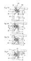
- the supports 3 and 4 are connected via two connecting elements 5 with the frame parts 1 and 2, as shown in FIGS. 2 to 4 in detail.
- connection shown with the frame part 1 on the example of the lower connection of the supports 3 consists essentially of a connecting element 5, which can be inserted into a groove-shaped recess 6 on the frame part 1 and latched there.
- the groove-shaped recess is formed by a substantially U-shaped profile 8, which has two legs 7, 8 and a base 9. In the region of the free edge of the one leg 7, an inwardly pointing, hook-shaped projection 10 is arranged.
- the connecting element 5 has a projection 11 which engages in the locked state of the connecting part 5 on the hook-shaped projection 10 and thus prevents unintentional pulling out of the connecting part 5 from the groove 6.
- the connecting element 5 has a groove 12, in which an elastic element 13 is inserted in the form of a cord which protrudes beyond the groove and may for example consist of rubber.
- On the base 9 side facing the connecting element 5 has two webs 14 and 15, which provide for an exact positioning or fixing of the connecting element 5 in the groove 6.
- the connecting element 5 has a central groove 16, in which a connecting bracket 17 is received, which establishes the connection to the support 3 and 4 respectively.
- the connecting bracket 17 has at its recorded in the central groove 16 end 18 a thickening, which prevents the connecting bracket 17 from the connecting element 5, in particular in the installed state of the connecting element 5, is pulled out.
- the connecting element is initially inserted with the webs 14, 15 into the groove 6 during installation.
- the web 14 then slides on the wall 8 of the U-shaped profile in the interior of the groove until the elastic element 13 also comes into contact with the wall 8.
- the opposing surface 19 of the connecting element 15 comes into abutment with the projection 10.
- the elastic element 13 is then compressed and, if necessary, the wall 7 is pressed slightly outwards until the webs 14 and 15 have reached the base 9 of the groove 6.
- the projection 11 engages behind the projection 10, whereby the connecting element 5 is engaged in the groove 6.
- the projection 11 is pressed firmly behind the hook-like projection 10, so that inadvertent withdrawal of the connecting element 5 is prevented from the groove 6.
Landscapes
- Engineering & Computer Science (AREA)
- Transportation (AREA)
- Mechanical Engineering (AREA)
- Aviation & Aerospace Engineering (AREA)
- Chair Legs, Seat Parts, And Backrests (AREA)
- Micro-Organisms Or Cultivation Processes Thereof (AREA)
Description
- Die Erfindung betrifft einen Sessel, insbesondere von Sesselliften, mit einem Rahmen und am Rahmen befestigten Auflagen, mit einem elastischen Verbindungselement, das zur Verbindung der Auflagen mit dem Rahmen an den Auflagen befestigt ist, wobei am Rahmen eine Vertiefung vorgesehen ist, in die das Verbindungselement einsetzbar und in dieser auf einer Seite der Vertiefung mittels einer Rastanordnung festlegbar ist.
- Aus der US-A-3037814 ist ein Sessel und aus der CH-A-664739 ist ein Fahrzeugsitz bekannt, bei denen an Auflagen elastische Elemente bzw. Zapfen vorgesehen sind, mit denen die Auflagen an Rahmen befestigt werden können. Dazu sind an den Rahmen Vertiefungen vorgesehen, in welche die Verbindungselemente einsetzbar und darin mittels einer Rastanordnung festlegbar sind.
- Es ist auch bekannt, die Auflagen von Sesselliftsesseln mit dem Rahmen zu vernieten, zu verschrauben oder zu verkleben. Dies hat jedoch den Nachteil, dass mechanische Arbeiten, wie das Bohren von Löchern und dgl., notwendig sind und die Verbindungen bei einem Austausch der Auflagen häufig auch nicht ohne weiteres wieder gelöst werden können.
- Der Erfindung liegt daher die Aufgabe zu Grunde, eine Möglichkeit anzugeben, die Auflagen auf einem Rahmen von Sesseln, insbesondere von Sesselliften, einfach und dauerhaft zu befestigen, wobei aber ein späteres Lösen dieser Verbindung ohne Probleme möglich sein soll.
- Gelöst wird diese Aufgabe mit einem Sessel mit den Merkmalen des Anspruches 1.
- Beim erfindungsgemäßen Sessel werden die Auflagen über eine Rastverbindung mit dem Rahmen verbunden, sodass ein sehr einfaches Befestigen der Auflagen am Rahmen möglich ist. Damit die Rastverbindung wieder gelöst werden kann, ist des weiteren ein elastisches Element vorgesehen, das auf der der Rastanordnung gegenüberliegenden Seite angeordnet ist und das deformiert werden kann, um die Rastverbindung zu lösen.
- Bevorzugte Ausführungsformen der Erfindung sind Gegenstand der Unteransprüche.
- Weitere Merkmale und Vorteile der Erfindung ergeben sich aus der nachfolgenden Beschreibung eines Ausführungsbeispieles der Erfindung unter Bezugnahme auf die Zeichnungen.
- Es zeigt:
- Fig. 1 den Sessel eines Sesselliftes im Schrägriss;
- Fig. 2 ein Detail des Sessels von Fig. 1 im Bereich einer Verbindung einer Auflage mit einem Rahmen in vergrößertem Maßstab;
- die Fig. 3a, 3b und 3c das Detail von Fig. 2 in einem weiter vergrößertem Maßstab in den einzelnen Phasen des Verbindens einer Auflage mit dem Rahmen; und
- Fig. 4 das selbe Detail im Moment des Lösens der Verbindung bei der Demontage.
- In Fig. 1 ist ein Sessel eines Sesselliftes dargestellt, der aus einem Rahmen mit zwei Rahmenteilen 1 und 2 besteht. Der Rahmenteil 1 ist eine Rahmenkonstruktion für die Rückenlehne, auf der vier Auflagen 3 befestigt sind. Der Rahmenteil 2 ist die Rahmenkonstruktion für die Sitzfläche, auf der ebenfalls vier Auflagen 4 befestigt sind. Die Auflagen 3 und 4 sind über jeweils zwei Verbindungselemente 5 mit den Rahmenteilen 1 und 2 verbunden, wie sie in den Fig. 2 bis 4 im Detail dargestellt sind.
- Wie die Fig. 2 bis 4 zeigen, besteht die am Beispiel der unteren Verbindung der Auflagen 3 dargestellte Verbindung mit dem Rahmenteil 1 im wesentlichen aus einem Verbindungselement 5, das in eine nutenförmige Vertiefung 6 am Rahmenteil 1 eingesteckt und dort verrastet werden kann. Die nutenförmige Vertiefung wird durch ein im wesentlichen U-förmiges Profil 8 gebildet, das zwei Schenkel 7, 8 und eine Basis 9 aufweist. Im Bereich des freien Randes des einen Schenkels 7 ist ein nach innen weisender, hakenförmiger Vorsprung 10 angeordnet. Das Verbindungselement 5 weist einen Ansatz 11 auf, der im verrasteten Zustand des Verbindungsteiles 5 am hakenförmigen Vorsprung 10 einrastet und somit ein unbeabsichtigtes Herausziehen des Verbindungsteiles 5 aus der Nut 6 verhindert. An der dem Ansatz 11 gegenüberliegenden Seite weist das Verbindungselement 5 eine Nut 12 auf, in die ein elastisches Element 13 in Form einer Schnur eingelegt ist, die über die Nut hinausragt und z.B. aus Gummi bestehen kann. Auf der der Basis 9 zugewandten Seite weist das Verbindungselement 5 zwei Stege 14 und 15 auf, die für eine exakte Positionierung bzw. Festlegung des Verbindungselementes 5 in der Nut 6 sorgen.
- Das Verbindungselement 5 weist eine zentrale Nut 16 auf, in der ein Verbindungsbügel 17 aufgenommen ist, der die Verbindung zur Auflage 3 bzw. 4 herstellt. Der Verbindungsbügel 17 weist an seinen in der zentralen Nut 16 aufgenommenen Ende 18 eine Verdickung auf, die verhindert, dass der Verbindungsbügel 17 aus dem Verbindungselement 5, insbesondere im eingebauten Zustand des Verbindungselementes 5, herausgezogen wird.
- Wie die Fig. 3a, 3b und 3c zeigen, wird das Verbindungselement beim Einbau zunächst mit den Stegen 14, 15 in die Nut 6 eingesetzt. Der Steg 14 gleitet dann an der Wand 8 des U-förmigen Profiles in das Innere der Nut, bis das elastische Element 13 ebenfalls in Anlage an die Wand 8 kommt. Gleichzeitig kommt die gegenüberliegende Fläche 19 des Verbindungselementes 15 in Anlage an den Vorsprung 10. Durch noch tieferes Hineindrücken des Verbindungselementes 5 in die Nut 6 wird anschließend das elastische Element 13 zusammengedrückt und ggf. die Wand 7 etwas nach außen gedrückt, bis die Stege 14 und 15 die Basis 9 der Nut 6 erreicht haben. In diesem Moment hintergreift der Ansatz 11 den Vorsprung 10, womit das Verbindungselement 5 in der Nut 6 eingerastet ist. Durch das elastische Element 13 wird der Ansatz 11 fest hinter den hakenartigen Vorsprung 10 gedrückt, sodass ein unbeabsichtigtes Herausziehen des Verbindungselementes 5 aus der Nut 6 verhindert wird.
- Damit des weiteren verhindert wird, dass das Verbindungselement 5 durch starkes Anziehen an einer Auflage 3 aus der Nut 6 "herausgedreht" wird, obwohl die Rastverbindung 10, 11 zunächst erhalten bleibt, ist der Steg 14 vorgesehen, der mit seiner Spitze in einer Ecke der Basis der Nut 6 festgelegt ist.
- Zum Lösen der Rastverbindung kann, wie in Fig. 4 gezeigt ist, mit einem Werkzeug 20, z.B. einem Schraubenzieher, an einer Lippe 21 angesetzt werden, um durch Verdrehen des Werkzeuges 20 im Uhrzeigersinn den Ansatz 11 hinter dem hakenartigen Vorsprung 10 herauszuheben, worauf das Verbindungselement 5 aus der Nut 6 herausgezogen werden kann. Dieses Herausdrücken des Ansatzes 11 hinter dem Vorsprung 10 wird durch das elastische Element 13 ermöglicht, das in dieser Phase soweit zusammengedrückt werden kann, dass die Rastverbindung 10, 11 gelöst wird.
Claims (9)
- Sessel, insbesondere von Sesselliften, mit einem Rahmen (1, 2) und am Rahmen (1, 2) befestigten Auflagen (3, 4),mit einem elastischen Verbindungselement (5), das zur Verbindung der Auflagen (3, 4) mit dem Rahmen (1, 2) an den Auflagen (3, 4) befestigt ist, wobei am Rahmen (1, 2) eine Vertiefung (6) vorgesehen ist, in die das Verbindungselement (5) einsetzbar und in dieser auf einer Seite der Vertiefung (6) mittels einer Rastanordnung (10, 11) festlegbar ist, dadurch gekennzeichnet, dass das Verbindungselement (5) auf der der Rastanordnung (10, 11) gegenüberliegenden Seite ein elastisches Element (13) aufweist, das im in der Vertiefung (6) eingesetzten Zustand des Verbindungselementes (5) eine Vorspannkraft erzeugt, welche die Rastanordnung (10, 11) in die Schließstellung drückt dass die Vertiefung (6) nutenförmig ausgeführt ist und dass das elastische Element (13) ein elastisches, gegebenenfalls profiliertes Band oder eine elastische Schnur, z.B. aus Gummi, ist.
- Sessel nach Anspruch 1, dadurch gekennzeichnet, dass die Rastanordnung (10, 11) einen hakenartigen Vorsprung (10) auf der Innenseite der nutenförmigen Vertiefung (6) aufweist, dem ein Ansatz (11) am Verbindungselement (5) zugeordnet ist.
- Sessel nach Anspruch 2, dadurch gekennzeichnet, dass das Verbindungselement (5) neben dem Ansatz (11) eine Lippe (21) aufweist, die sich in eingebautem Zustand des Verbindungselementes (5) in den Bereich der Mündung der nutenförmigen Vertiefung (6) erstreckt.
- Sessel nach einem der Ansprüche 1 bis 3, dadurch gekennzeichnet, dass das elastische Element (13) in einer Nut (12) im Verbindungselement (5) aufgenommen ist.
- Sessel nach einem der Ansprüche 1 bis 4, dadurch gekennzeichnet, dass das Verbindungselement (5) einen Steg (14) aufweist, der sich im in der Vertiefung (6) eingesetzten Zustand des Verbindungselementes (5) in einer Ecke an der Basis (9) der nutenförmigen Vertiefung (6) abstützt.
- Sessel nach Anspruch 5, dadurch gekennzeichnet, dass das Verbindungselement (5) einen zweiten Steg (15) aufweist, der sich im in der Vertiefung (6) eingesetzten Zustand des verbindungselementes (5) im Bereich der zweiten Ecke an der Basis (9) der nutenförmigen Vertiefung (6) abstützt.
- Sessel nach einem der Ansprüche 1 bis 6, dadurch gekennzeichnet, dass das Verbindungselement (5) eine zentrale Nut (16) aufweist, in der ein Verbindungsbügel (17) aufgenommen ist, der an der Auflage (3, 4) angeordnet ist.
- Sessel nach Anspruch 7, dadurch gekennzeichnet, dass der Verbindungsbügel (17) an seinem in der zentralen Nut (16) aufgenommenen Ende ein Verdickung (18) aufweist.
- Sessel nach Anspruch 7 oder 8, dadurch gekennzeichnet, dass die Nut (16) zu der Seite, auf der das elastische Element (13) angebracht ist, hin offen ist.
Priority Applications (1)
| Application Number | Priority Date | Filing Date | Title |
|---|---|---|---|
| AT03450263T ATE327922T1 (de) | 2002-12-04 | 2003-11-27 | Sessel mit lösbar befestigten auflagen, insbesondere für einen sessellift. |
Applications Claiming Priority (2)
| Application Number | Priority Date | Filing Date | Title |
|---|---|---|---|
| AT18162002 | 2002-12-04 | ||
| AT0181602A AT413517B (de) | 2002-12-04 | 2002-12-04 | Sessel für sessellifte |
Publications (2)
| Publication Number | Publication Date |
|---|---|
| EP1426232A1 EP1426232A1 (de) | 2004-06-09 |
| EP1426232B1 true EP1426232B1 (de) | 2006-05-31 |
Family
ID=32303972
Family Applications (1)
| Application Number | Title | Priority Date | Filing Date |
|---|---|---|---|
| EP03450263A Expired - Lifetime EP1426232B1 (de) | 2002-12-04 | 2003-11-27 | Sessel mit lösbar befestigten Auflagen, insbesondere für einen Sessellift. |
Country Status (2)
| Country | Link |
|---|---|
| EP (1) | EP1426232B1 (de) |
| AT (2) | AT413517B (de) |
Families Citing this family (4)
| Publication number | Priority date | Publication date | Assignee | Title |
|---|---|---|---|---|
| GB2408201B (en) * | 2003-11-21 | 2006-03-01 | Armon Ltd | Push chair seat attachment |
| GB2420705A (en) * | 2006-01-25 | 2006-06-07 | Armon Ltd | Child's high chair |
| GB0701663D0 (en) * | 2007-01-29 | 2007-03-07 | Creactive Design | Seating arrangement |
| FR2977541B1 (fr) * | 2011-07-04 | 2014-01-24 | Peugeot Citroen Automobiles Sa | Dispositif de fixation d'une coiffe de garnissage de siege automobile sur l'armature de siege |
Family Cites Families (7)
| Publication number | Priority date | Publication date | Assignee | Title |
|---|---|---|---|---|
| US3037814A (en) * | 1959-09-14 | 1962-06-05 | Shwayder Brothers Inc | Backrest assembly for chairs |
| JPS56149266A (en) * | 1980-04-18 | 1981-11-19 | Yamaha Motor Co Ltd | Seat for autobicycle |
| CH664739A5 (en) * | 1984-07-12 | 1988-03-31 | Hess Carrosserie | Upholstered vehicle seat with removable cover - has metal frame embedded in squab and backrest foam cushions, with exposed portions for cover fastening |
| US4822092A (en) * | 1988-03-28 | 1989-04-18 | Chrysler Motors Corporation | Composite anchor attaching arrangement for vehicle seat |
| FR2729439B1 (fr) * | 1995-01-16 | 1997-04-04 | Faure Bertrand Equipements Sa | Systeme de montage d'un element de siege sur un vehicule automobile |
| JP3842530B2 (ja) * | 2000-07-19 | 2006-11-08 | 株式会社ニフコ | 物品保持具 |
| FR2814709B1 (fr) * | 2000-10-03 | 2003-02-07 | Peugeot Citroen Automobiles Sa | Siege de vehicule automobile |
-
2002
- 2002-12-04 AT AT0181602A patent/AT413517B/de not_active IP Right Cessation
-
2003
- 2003-11-27 EP EP03450263A patent/EP1426232B1/de not_active Expired - Lifetime
- 2003-11-27 AT AT03450263T patent/ATE327922T1/de active
Also Published As
| Publication number | Publication date |
|---|---|
| ATE327922T1 (de) | 2006-06-15 |
| ATA18162002A (de) | 2005-08-15 |
| EP1426232A1 (de) | 2004-06-09 |
| AT413517B (de) | 2006-03-15 |
Similar Documents
| Publication | Publication Date | Title |
|---|---|---|
| DE102010022556B3 (de) | Vorrichtung zum Befestigen eines Solarmoduls | |
| EP2313662B1 (de) | Befestigungsbinder | |
| DE102007035648A1 (de) | Tafelförmiges Paneel mit separatem Rastelement | |
| WO1980001709A1 (fr) | Element de couplage pour supports ayant une rainure longitudinale a contre-depouille | |
| DE202010000545U1 (de) | Befestigungseinrichtung für einen Holm oder eine Leiste an einem C-Profil | |
| EP3263792B1 (de) | Klammersystem für paneele | |
| EP0768936A1 (de) | Parkett-verlegehilfe | |
| EP3043123A1 (de) | Mehrteiliger dachhaken und befestigungssystem | |
| EP1426232B1 (de) | Sessel mit lösbar befestigten Auflagen, insbesondere für einen Sessellift. | |
| DE202012006839U1 (de) | Befestigungsklemme für Solarmodule | |
| DE202009005090U1 (de) | Anordnung zur Befestigung von Modulen einer Photovoltaik-Einrichtung oder von Solarpaneelen | |
| WO2004111471A1 (de) | Hochlastverbindungselement für wände | |
| DE102008045004A1 (de) | Elektrisches Unterputz-Installationsgerät mit einem Geräteeinsatz mit Trägerplatte und einem hieran befestigten Abdeckrahmen | |
| DE8623135U1 (de) | Zierleiste | |
| DE10020216A1 (de) | Abziehschutz für elektronische Installationsgeräte, vorzugsweise für die Gebäudesystemtechnik | |
| EP4411276A2 (de) | Montagesystem | |
| EP2722952A2 (de) | Elektrisches Installationsgerät | |
| AT11820U1 (de) | Halteclip zur befestigung einer mit zwei längsnuten versehenen abdeckleiste | |
| DE4428989C1 (de) | Wandabschlußprofil für Küchenschränke oder Arbeitsplatten von Einbauküchen | |
| DE20302306U1 (de) | Verbindungselement für den Möbelbau und Verbindungsanordnung | |
| DE19607935C2 (de) | Befestigungsvorrichtung für Sockelblenden | |
| EP0984107A2 (de) | Profilschiene und Verbindungselement für eine Tragvorrichtung | |
| EP1406361B9 (de) | Montageelement für Geräteeinbaukanäle | |
| DE102008030319B4 (de) | Schiebetüranlage | |
| DE7241842U (de) | Vorrichtung zur Befestigung der Dachhaut an dem Verkleidungsprofil einer Dachrandverkleidung |
Legal Events
| Date | Code | Title | Description |
|---|---|---|---|
| PUAI | Public reference made under article 153(3) epc to a published international application that has entered the european phase |
Free format text: ORIGINAL CODE: 0009012 |
|
| AK | Designated contracting states |
Kind code of ref document: A1 Designated state(s): AT BE BG CH CY CZ DE DK EE ES FI FR GB GR HU IE IT LI LU MC NL PT RO SE SI SK TR |
|
| AX | Request for extension of the european patent |
Extension state: AL LT LV MK |
|
| RTI1 | Title (correction) |
Free format text: CHAIR WITH RELEASABLY ATTACHED COVERS, ESPECIALLY FOR A SKI LIFT. |
|
| 17P | Request for examination filed |
Effective date: 20040701 |
|
| 17Q | First examination report despatched |
Effective date: 20041208 |
|
| AKX | Designation fees paid |
Designated state(s): AT IT |
|
| REG | Reference to a national code |
Ref country code: DE Ref legal event code: 8566 |
|
| RBV | Designated contracting states (corrected) |
Designated state(s): AT IT |
|
| GRAP | Despatch of communication of intention to grant a patent |
Free format text: ORIGINAL CODE: EPIDOSNIGR1 |
|
| RIN1 | Information on inventor provided before grant (corrected) |
Inventor name: SWITZENY, KURT C/O CONTAXX GMBH |
|
| GRAS | Grant fee paid |
Free format text: ORIGINAL CODE: EPIDOSNIGR3 |
|
| GRAA | (expected) grant |
Free format text: ORIGINAL CODE: 0009210 |
|
| AK | Designated contracting states |
Kind code of ref document: B1 Designated state(s): AT IT |
|
| PG25 | Lapsed in a contracting state [announced via postgrant information from national office to epo] |
Ref country code: IT Free format text: LAPSE BECAUSE OF FAILURE TO SUBMIT A TRANSLATION OF THE DESCRIPTION OR TO PAY THE FEE WITHIN THE PRESCRIBED TIME-LIMIT;WARNING: LAPSES OF ITALIAN PATENTS WITH EFFECTIVE DATE BEFORE 2007 MAY HAVE OCCURRED AT ANY TIME BEFORE 2007. THE CORRECT EFFECTIVE DATE MAY BE DIFFERENT FROM THE ONE RECORDED. Effective date: 20060531 |
|
| PLBE | No opposition filed within time limit |
Free format text: ORIGINAL CODE: 0009261 |
|
| STAA | Information on the status of an ep patent application or granted ep patent |
Free format text: STATUS: NO OPPOSITION FILED WITHIN TIME LIMIT |
|
| 26N | No opposition filed |
Effective date: 20070301 |
|
| PGFP | Annual fee paid to national office [announced via postgrant information from national office to epo] |
Ref country code: IT Payment date: 20161123 Year of fee payment: 14 Ref country code: AT Payment date: 20161129 Year of fee payment: 14 |
|
| REG | Reference to a national code |
Ref country code: AT Ref legal event code: MM01 Ref document number: 327922 Country of ref document: AT Kind code of ref document: T Effective date: 20171127 |
|
| PG25 | Lapsed in a contracting state [announced via postgrant information from national office to epo] |
Ref country code: AT Free format text: LAPSE BECAUSE OF NON-PAYMENT OF DUE FEES Effective date: 20171127 |
|
| PG25 | Lapsed in a contracting state [announced via postgrant information from national office to epo] |
Ref country code: IT Free format text: LAPSE BECAUSE OF NON-PAYMENT OF DUE FEES Effective date: 20171127 |