EP1426252B1 - Système et méthode de protection des piétons - Google Patents
Système et méthode de protection des piétons Download PDFInfo
- Publication number
- EP1426252B1 EP1426252B1 EP20030027823 EP03027823A EP1426252B1 EP 1426252 B1 EP1426252 B1 EP 1426252B1 EP 20030027823 EP20030027823 EP 20030027823 EP 03027823 A EP03027823 A EP 03027823A EP 1426252 B1 EP1426252 B1 EP 1426252B1
- Authority
- EP
- European Patent Office
- Prior art keywords
- pedestrian protection
- protection system
- sensors
- mass
- impact
- Prior art date
- Legal status (The legal status is an assumption and is not a legal conclusion. Google has not performed a legal analysis and makes no representation as to the accuracy of the status listed.)
- Expired - Lifetime
Links
Images






Classifications
-
- B—PERFORMING OPERATIONS; TRANSPORTING
- B60—VEHICLES IN GENERAL
- B60R—VEHICLES, VEHICLE FITTINGS, OR VEHICLE PARTS, NOT OTHERWISE PROVIDED FOR
- B60R21/00—Arrangements or fittings on vehicles for protecting or preventing injuries to occupants or pedestrians in case of accidents or other traffic risks
- B60R21/01—Electrical circuits for triggering passive safety arrangements, e.g. airbags, safety belt tighteners, in case of vehicle accidents or impending vehicle accidents
- B60R21/013—Electrical circuits for triggering passive safety arrangements, e.g. airbags, safety belt tighteners, in case of vehicle accidents or impending vehicle accidents including means for detecting collisions, impending collisions or roll-over
- B60R21/0136—Electrical circuits for triggering passive safety arrangements, e.g. airbags, safety belt tighteners, in case of vehicle accidents or impending vehicle accidents including means for detecting collisions, impending collisions or roll-over responsive to actual contact with an obstacle, e.g. to vehicle deformation, bumper displacement or bumper velocity relative to the vehicle
-
- B—PERFORMING OPERATIONS; TRANSPORTING
- B60—VEHICLES IN GENERAL
- B60R—VEHICLES, VEHICLE FITTINGS, OR VEHICLE PARTS, NOT OTHERWISE PROVIDED FOR
- B60R21/00—Arrangements or fittings on vehicles for protecting or preventing injuries to occupants or pedestrians in case of accidents or other traffic risks
- B60R21/34—Protecting non-occupants of a vehicle, e.g. pedestrians
- B60R21/38—Protecting non-occupants of a vehicle, e.g. pedestrians using means for lifting bonnets
-
- B—PERFORMING OPERATIONS; TRANSPORTING
- B60—VEHICLES IN GENERAL
- B60R—VEHICLES, VEHICLE FITTINGS, OR VEHICLE PARTS, NOT OTHERWISE PROVIDED FOR
- B60R19/00—Wheel guards; Radiator guards, e.g. grilles; Obstruction removers; Fittings damping bouncing force in collisions
- B60R19/02—Bumpers, i.e. impact receiving or absorbing members for protecting vehicles or fending off blows from other vehicles or objects
- B60R19/48—Bumpers, i.e. impact receiving or absorbing members for protecting vehicles or fending off blows from other vehicles or objects combined with, or convertible into, other devices or objects, e.g. bumpers combined with road brushes, bumpers convertible into beds
- B60R19/483—Bumpers, i.e. impact receiving or absorbing members for protecting vehicles or fending off blows from other vehicles or objects combined with, or convertible into, other devices or objects, e.g. bumpers combined with road brushes, bumpers convertible into beds with obstacle sensors of electric or electronic type
-
- B—PERFORMING OPERATIONS; TRANSPORTING
- B60—VEHICLES IN GENERAL
- B60R—VEHICLES, VEHICLE FITTINGS, OR VEHICLE PARTS, NOT OTHERWISE PROVIDED FOR
- B60R21/00—Arrangements or fittings on vehicles for protecting or preventing injuries to occupants or pedestrians in case of accidents or other traffic risks
- B60R21/01—Electrical circuits for triggering passive safety arrangements, e.g. airbags, safety belt tighteners, in case of vehicle accidents or impending vehicle accidents
- B60R2021/0104—Communication circuits for data transmission
- B60R2021/01081—Transmission medium
- B60R2021/01095—Transmission medium optical
Definitions
- the invention relates to a pedestrian protection system for a vehicle, comprising a sensor for detecting a deformation caused by an impact of an object on the vehicle, means for evaluating the signals supplied by the sensor, so that information about the characteristics of the impact can be supplied, and Device for lifting a hood, in particular a hood, of the vehicle, which can be actuated in dependence on the information about the characteristics of the impact.
- the invention further relates to a method for protecting pedestrians.
- an elevation of the hood for damping the impact also takes place, but only after the detection of the contact between the vehicle and the pedestrian by sensors arranged on the front edge of the hood.
- an actuating device for use in motor vehicles with a memory storing a compressed pressure medium and a pneumatic actuator
- the reservoir and the pneumatic actuator are connected to one another and the connection can be closed by means of a valve and at the pneumatic actuator comprises an axially and radially elastic hose, wherein the diameter of the hose is increased by pressurizing the pneumatic actuator and shortens the length of the hose.
- the usable by the shortening of the hose path serves to actuate a further, downstream device.
- a method for impact detection in a vehicle is also known.
- the relative acceleration between the motor vehicle and the impact object is determined using pre-crash sensors, wherein the relative mass of the impact object is determined from the relative movement and the restraining force.
- the parameters determining the severity of the accident are the effective mass of the impact object and the impact speed or energy.
- protection systems are then activated.
- the effective acceleration is determined from the relative deceleration and deceleration of the vehicle. Two different possibilities are used to calculate the effective mass: firstly, the acceleration a measured by the acceleration sensors in the vehicle and secondly the force F.
- the effective mass together with the relative speed is then the measure of the severity of the accident.
- Actuator in the context of the present disclosure are to be understood primarily devices based on activate a signal with the aid of auxiliary energy.
- the invention has for its object to provide a pedestrian protection system and a method for the protection of pedestrians, which eliminate the disadvantages of the prior art, in particular the impact of a pedestrian can be reliably and inexpensively recognized means, in particular to decide whether a Pedestrian protection is to be activated and wherein a mechanical actuation with fast response or small adjustment time is provided.
- the invention is based on the generic system in that the means for evaluating the induced deformations can determine a deformation work, that the means for evaluating, taking into account time information, which is detected by the sensor, can determine an intrusion rate of the object, taking into account the deformation work and the intrusion speed a parameter characterizing the mass of the object can be determined and that the intrusion speed and the mass of the object are taken into account in order to decide whether the device for lifting the hood is actuated.
- the total kinetic energy resulting from the relative velocity of the object and the vehicle and of the object mass is converted into deformation work.
- the pedestrian protection system according to the invention is particularly advantageous in that the means for evaluating determine the deformation work on the basis of a stored table and / or a calculation.
- the table or calculation relates different deformation patterns with the deformation work deposited in the vehicle, so that, with knowledge of the deformation pattern, the deformation work is available as one of the output variables for determining the mass or the mass parameter.
- the dynamic factor results from the dynamics of the signal curve.
- a dynamic factor is taken into account, for example, that the kinetic energy is not implemented exclusively in the form of deformation work in the vehicle, but that, for example, the leg of a pedestrian, which bounces on the sensors, also undergoes a deformation.
- the dynamic factor is a correction term that takes into account the real conditions on impact.
- the pedestrian protection system according to the invention is further developed in a particularly advantageous manner that at a mass m 0 or an effective mass m eff between about 5 kg and 20 kg activating a pedestrian protection is possible and that at a mass m 0 or an effective mass m eff less than about 5 kg and greater than 20 kg prevents the activation of pedestrian protection.
- a mass window is provided, which allows only in the case activating the pedestrian protection, when there is a high probability of the impact of a pedestrian. It is prevented that effective masses below about 5 kg, a pedestrian protection is activated, so that, for example, the triggering of pedestrian protection in clashes with small animals is prevented. Also, an activation of the pedestrian protection is to be prevented at effective masses above 20 kg.
- the invention is further developed in a particularly advantageous manner in that the sensor system comprises a plurality of sensors having a plurality of sensitive areas, wherein the sensitive areas are located at different locations of the vehicle, in particular the vehicle front.
- the measure that a sensor has several sensitive areas the number of required sensors can be significantly reduced. In doing so, one deliberately accepts that information about the place of impact is at least partially lost.
- This is understandable in the background that in most systems anyway only a single measure is available to dampen the impact, either by an airbag or, as preferably in the context of the system according to the invention, by lifting the hood in the rear area , Even if the information regarding the place of impact is lost, so remains as essential information the one about the characteristics of the impact received. For example, the impact of a pedestrian can be distinguished from a parking bump.
- the pedestrian protection system according to the invention is further developed in a particularly advantageous manner in that the sensors or the sensitive areas of the sensors are arranged along a bumper of the vehicle.
- the requirement is taken into account that the impact of the pedestrian is detected as early as possible, that is, when using contact sensors by an array of sensors as far ahead of the vehicle.
- a single sensor may extend over the entire length of the bumper, with a plurality of sensitive regions for sensing the characteristic of the impact along the length of the sensor.
- the sensitive areas associated with a sensor may be arranged at regular intervals along a bumper of the vehicle. In this way, a sensor can cover the entire area over which it extends with a uniform characteristic.
- the sensors may also be useful for sensitive areas of adjacent sensors to be offset from one another or arranged next to one another such that signals of different intensities are delivered on impact of an object by neighboring sensors. If the sensitive areas of adjacent sensors were not arranged offset, that is to say in the case of the longitudinal extent of the sensors along the bumper of the vehicle, the sensors would in many cases be subjected to the same or similar deformation and thus deliver the same or similar signal intensities. By now being staggered, the sensors generally provide different signal intensities in turn can be used to determine the impact characteristics and thus the detection of the object.
- the pedestrian protection system according to the invention is particularly advantageously formed in that the sensors are optical fiber sensors, at one end of which light can be coupled and at the other end of the intensity of leaking light can be measured that the sensitive areas of the sensors by changing the Surface of the optical fiber sensors are created and that depending on the deformation of the sensitive areas more or less light can be coupled out of the sensitive areas, so that the measured intensity of leaking light can be used as a measure of the deformation of the sensitive areas.
- Such sensors for example of polymethyl methacrylate, are particularly suitable for the realization of the present invention for a number of reasons.
- the optical fiber sensors are flexible, they have a low weight, a high mechanical strength, and are insensitive to temperature. Furthermore, there are no problems in terms of electromagnetic compatibility.
- the optical fiber sensors are preferably embedded in a matrix material.
- a certain amount of light emerges from the sensitive area, which results from the geometric conditions. If the sensor is bent, this can lead to an influence on the exiting light intensity, which results essentially from the laws of geometric optics.
- an actuating device which has a pressure supply device and an actuator connected to the pressure supply device by means of a valve, in particular a pneumatic actuator that the device for lifting the hood with the actuator is connectable and by Pressurization of the actuator is actuated and that the device for lifting the hood at least one hood holding element and at least one latch, wherein upon actuation of the device, the hood-holding element is adjustable in an unlocked position.
- a pressure supply device as an energy source
- a self-sufficient unit is provided, wherein the downstream device for lifting the hood exploits the available by contraction of the pneumatic actuator longitudinal force to release the lock of the device for lifting the hood.
- the bolt prevents the bonnet from being lifted by hand.
- Another advantage is that the device for lifting the hood has reversible properties, which would not be the case, for example, with actuators with explosive devices.
- the actuating device and the device for lifting the hood are connected to each other by means of an intermediate element.
- an intermediate element By providing an intermediate element, the flexibility of the safety device is ensured, since thus the actuating device and the device for lifting the hood are separately produced and interchangeable.
- the hood retaining element is pivotable about a holding element axis and is connected to a support element, wherein the support element has at least one, preferably two slots, in which the axis slides in an unlocked or a locking state.
- the provision of a support element and the connection of the hood-holding element by means of a rotatable shaft to this support member is particularly advantageous, since thus the device for lifting the hood is made stable and reliable.
- the slot is provided at one end of the support element, which faces the actuating device, wherein the slot is dimensioned such that its length substantially corresponds to the shortening of the actuator at a pressurization.
- the at least one latch may be configured such that a first part of the latch is substantially U-shaped and is pivotally connected to the support element and a second part of the latch can be connected to the intermediate element by means of an intermediate element axis ,
- a first part of the latch is substantially U-shaped and is pivotally connected to the support element and a second part of the latch can be connected to the intermediate element by means of an intermediate element axis .
- the second part of the at least one bolt is rail-shaped and the intermediate element axis runs at a pressure in the rail. This ensures that on the one hand, the bolt is an active connection between the two devices and that on the other hand, a Fehlentriegelung is not possible.
- the holding element axis and the intermediate element axis are fixedly connected to one another at both ends by means of at least one axis connection.
- this fixed connection is made possible that the rail-shaped part of the bolt parallel to the slot of the support element is arranged. This ensures that the holding element axis reaches an end position in which the hood holding elements lift the hood in an elevated position.
- the second part of the at least one bolt is formed integrally with the first substantially U-shaped part of the bolt, wherein the second part is formed as an extension of one of the opposing U-parts and with respect to this U Part includes an angle ⁇ , where ⁇ is equal to or preferably greater than 90 °.
- This one-piece design of the bolt increases its stability, wherein also a different shape of the first latch member than the U-shape can be provided.
- this advantageous embodiment allows a smaller deviation of the inactive position of the bolt with respect to the support element upon actuation of the device.
- a further advantageous embodiment provides that a second hood-holding element is provided, which is pivotally mounted on one of the actuating device facing away from the end of the support element, wherein the two hood-holding elements are synchronously actuated.
- the provision of a second hood-holding element requires a small additional effort and increases the stability and reliability of the hood mount as a whole.
- the two hood-holding elements are connected to each other at their upper, adjacent to the hood ends by means of a connecting element.
- the U-shaped part of the bolt and the holding element axis are dimensioned such that in the locking position, the holding element axis with the U-shaped part of the bolt positively and / or non-positively cooperates.
- the Holding element axis about which the holding element is pivotable is used as a counterpart bar.
- a particularly advantageous embodiment of the invention provides that the hood holding elements are connected to one another such that a trapezoidal hood holder is formed.
- the two holding elements form the two trapezoidal legs.
- the pressure supply device of the actuating device comprises a pump, in particular a micropump, and a pressure accumulator arranged between the pump and the valve, wherein the valve is a high-speed valve.
- the valve is a high-speed valve.
- the pressure supply device of the actuating device has a pump, in particular a micropump, which is connected to the valve, wherein a pressure accumulator is provided, which extends to reduce the space occupied by the pressure supply device space in the actuator.
- the actuator is on the one hand firmly connected to the pressure supply device, wherein preferably a pendulum connection is provided, and on the other hand is connected by means of the intermediate element with the actuating device. This measure leads to increased security of the connection.
- the actuator can preferably be actuated by compressed air, gas or liquid.
- the invention further relates to a method for protecting pedestrians for implementation with a system according to the invention.
- a system according to the invention In this way, the advantages and special features of the system according to the invention are also implemented in the context of a method.
- the invention is based on the finding that determination of the deformation in the event of an impact and the acquisition of time information enable mass determination, which can ultimately be used as a decision criterion for triggering pedestrian protection.
- the number of sensors can be greatly reduced, resulting in significant cost savings. This cost saving results both from the reduction of the sensors themselves and from the simpler design of the evaluation.
- the lifting mechanism associated features of the invention allow a reliable design of the system, on the one hand, as regards the lifting of the hood, and on the other hand, as regards the locking of the hood.
- FIG. 1 shows a section of a motor vehicle with a system according to the invention.
- a motor vehicle 12 with a bumper 20 and a hood 60 is shown.
- the hood 60 is shown once in a solid line in the closed state and further in the raised state by a broken line. This raising of the hood 60 is to take place in the event of a collision with a pedestrian, so in this way additional space is created under the hood, so that is dampened by resulting deformation path of the impact of the pedestrian on the hood 60.
- the lifting is effected by a not shown in the lifting mechanism 58 arranged actuator.
- 20 sensors 14 are arranged at the front end of the bumper. These preferably extend over the entire width of the motor vehicle 12, that is to say over the length of the bumper 20, in order to be able to detect a pedestrian impact at all these points.
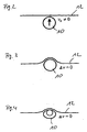
- FIG. 3 shows a schematic representation of an object 10 after the impact on a vehicle 12.
- k is a constant.
- FIG. 4 shows a schematic representation of a further object 10 after the impact on a vehicle 12.
- the object 10 shown here may be, for example, the deformable leg of a pedestrian.
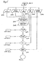
- FIG. 5 shows a flow chart for explaining a method according to the invention.
- step S09 it is determined whether the effective mass m eff in a mass window is between 5 kg and 20 kg. If this is not the case, then it is decided that a pedestrian protection is not activated ("do not fire").
- step S10 it is determined in step S10 whether the intrusion speed lies within a predetermined speed window between 20 km / h and 60 km / h. If the intrusion speed is less than 20 km / h or greater than 60 km / h, the pedestrian protection is not activated.
- step S11 If the intrusion speed lies within the predefined speed window, then it can still be checked in step S11 whether it is likely to be, for example, a leg taking into account the dynamic criteria provided from step S05. If it is not a leg, then the pedestrian protection, possibly in a wheelchair can not be triggered. If it is determined in step S11 that the impact was caused by a leg, then it is possible to proceed to step S12.
- the specific evaluation in step S11 may provide additional information in finely tuned systems, but in principle a decision based solely on the mass parameter and the intrusion rate is in most cases sufficient.
- step S12 it is further determined in step S12 on the basis of a comparison of the number of sensors from step S02 and the number of main maxima S06 whether the impact is likely to be caused by an object other than the predetermined object, for example by a leg, was effected. If the impact has been caused by another object, the pedestrian protection system will not be activated. However, if it is determined that it is unlikely to be another object, pedestrian protection will be activated.
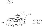
- FIG. 6 shows a contact sensor arrangement and a penetrating object.
- An object 10 may cause a certain deformation of the sensors 14 upon impact with the sensors 14, which in a characteristic manner depends on the shape of the object 10.
- the sensors 14 1 , 14 2 , 14 3 , 14 4 , 14 5 , 14 6 are deformed in different ways by the impact of the object 10, so that they also different signal intensities s 1 , s 2 , s 3 , s 4 , s 5 and s 6 deliver. If one sets the sensors 14 so that they deliver a greater signal intensity with greater deformation, then in the present graphically illustrated example, the signal intensity s 2 of the sensor 14 2 is approximately n times as large as the signal intensity s 1 of the sensor 14 1 .
- the signal intensity s 3 of the sensor 14 3 is approximately m times the signal intensity s 1 of the sensor 14 1 , where n and m are known factors, for example 2 and 4.
- n and m are known factors, for example 2 and 4.
- there is a characteristic relationship between the signal intensities which may also be characteristic of a particular type of object, for example the leg of a pedestrian.
- FIG. 7 shows three examples of contact sensor arrangements with a plurality of sensitive or active areas.
- the individual sensors 14a, 14b, 14c, 14d may have a different length than shown. Likewise, a different number of individual sensors 14a, 14b, 14c, 14d may be present than illustrated.
- Each individual sensor 14 has a plurality of active sensor regions 18. For example, 30 such active or sensitive sensor regions 18 per sensor 14 may be provided.
- FIG. 7 a shows an arrangement in which the sensitive areas 18 repeat regularly along the sensors 14. Furthermore, one can define sensor arrangements 22 via the various sensors, which also repeat themselves regularly. In this example, an object that is in a certain way with respect to any of the repeating Sensor arrangements 22 incident, always generate the same signal pattern. The signal pattern thus gives no information about which of the repeating devices 22 has been hit. However, the information about the characteristics of the impact is recorded.
- the sensitive regions 18 are likewise regularly distributed over the individual sensors 14. However, the distances of the sensitive areas 18 on the individual sensors are different. Thus, such a sensor arrangement would deliver different intensity patterns when an object hits, than when the object impinges on a sensor arrangement according to FIG. 7, whereby different information about the characteristics of the impact can be obtained by clever arrangement of the sensitive areas 18.
- FIG. 7 c shows yet another variant of the arrangement of sensitive regions 18 on the sensors 14, wherein it should be mentioned in particular that sensitive regions 18 with different dimensions are provided.
- sensors 14 and sensitive areas 18 of the sensors In addition to the arrangements of sensors 14 and sensitive areas 18 of the sensors given in FIG. 7, numerous other possibilities are conceivable which can bring about different advantages. For example, it is possible that the sensors 14 are not arranged in a straight line, so that in this way the sensitive areas 18 of the sensors can lie next to one another, ie at the same height.
- Figure 8 shows a plan view of the front end of a motor vehicle to illustrate the arrangement of sensors 14.
- an elastic foam 34 is arranged on a cross member 32.
- This foam 34 has, for example, a thickness of 60 to 70 mm.
- the optical fiber sensors 14 may for example be arranged on a steel strip, so that a total of a thickness of the sensor layer, for example, 1.5 to 2 mm is present.
- optical fiber sensors 14 may still follow a plastic outer skin, which is not shown in the present illustration and may have a thickness of, for example, 2 to 3 mm.
- FIG. 9 shows a sectional side view of a front end of a motor vehicle for explaining the provision of deformability. It is shown how the deformation path required for the deformation can be provided by mounting the optical sensor section 14 on a foam layer 34 arranged on a support 32, which is necessary for the protection of the leg. Above the optical sensors 14 is a plastic layer 40.
- FIG. 10 shows a sectional side view of a front region of a motor vehicle for explaining a further possibility for providing deformability.
- a plastic layer 40 is provided as the outer skin.
- the sensors 14 are located on a crash box 36.
- the crash box provides an elastic deformation behavior up to a certain force exerted on it, so that a detection can take place on the basis of the deformation of the optical sensors 14.
- FIG. 11 shows a detail of an optical fiber sensor 30 with a sensitive region in three different states a, b and c.
- the optical fiber sensor 30 has a sensitive area 18 that can be provided by surface treatment. By providing such a sensitive region 18, the light intensity emerging from the optical fiber sensor 30 can be changed in this sensitive region 18. This has the consequence that the exiting light intensity depends on the deformation state of the fiber sensor 30.
- the deformation state according to 11a the light intensity 18 emerging from the sensitive region 18 is reduced in comparison to the undeformed state according to FIG. 11b.
- the light intensity emerging from the sensitive region 18 is increased in comparison with the undeformed state according to FIG. 11b.
- FIG. 12 shows an arrangement of optical fiber sensors with light source 44 and detectors 46, 48.
- Two optical fiber sensors 28, 30 are arranged in a carrier material 42.
- the optical fiber sensor 28 is not provided with a sensitive area while the optical fiber sensor 30 is provided with a sensitive area 18; This is indicated by the broken line in the substrate 42.
- the light is passed through the optical fiber sensor 30 and finally reaches the other end 26 of the optical fiber sensor 30 with a remaining intensity Detector 46 the light intensity can be measured. If the sensitive area 18 of the optical fiber sensor 30 is deformed, this has an effect on the intensity of light emerging in this area and thus also on the intensity detected by the detector 46 for a given coupled light intensity from the light source 44.
- optical fiber sensor 28 In order to provide reliable measurement results, it is possible to arrange another optical fiber sensor 28 parallel to the optical fiber sensor 30, but this does not have a sensitive area. If light from the same light source 44, which is also used for the optical fiber sensor 30, is coupled into this optical conductor 28, the intensity signal output by the detector 48 can be input via a corresponding electronic circuit, which is symbolized here by an amplifier 50 for the light source 44 and thus for representing a reference circuit. Thus, for example, fluctuations the intensity emitted by the light source 44 is compensated.
- Figure 13 is a block diagram for explaining the system construction.
- the system according to the invention is arranged in an overall concept such that the sensor arrangement 14 communicates with an electronic control unit 16 via an interface device 52.
- This electronic control unit 16 may comprise a CAN interface so that additional information available on the CAN bus can be processed by the electronic control unit 16. Also, the CAN bus can be entered in this way from the sensor assembly 14 detected information.
- the electronic control unit 14 controls a power electronics 54, which can actuate an actuator 56 in dependence on the information detected by the sensor arrangement 14. This can then cause in the event of a pedestrian impact the setting up of the hood shown in Figure 1.
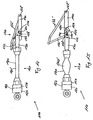
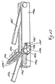
- FIG 14 shows a side view of a preferred lifting mechanism for a pedestrian protection system according to the invention in the rest position.
- the safety device 110 comprises an actuating device 120 and a device 130 for lifting an unillustrated engine hood of a motor vehicle.
- the actuating device 120 essentially has a pressure supply device 122 and an actuator 160, which comprises a radially and axially elastic hose 160 '.
- the pressure supply device 122 is connected to the actuator 160 by means of a high-speed valve 126.
- the hood lifting device 130 is in communication with the actuator 120 by means of an intermediate member 150 and has two hood retaining members 132 and 132 ', which are shown as two legs of a trapezoidal bracket.
- the two hood holding elements 132 and 132 ' are pivotably connected by a holding element axis 138 or 138' to a support element 140.
- the device 130 further comprises a latch 134, which is rotatably connected by means of a bearing 136 with the support member 140 and is connected by means of an intermediate element axis 152 with the intermediate element 150 in connection.
- the safety device is shown in an inactive position, in which the holding element axis 138 serves as a counterpart bar.
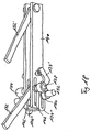
- FIG. 15 shows a side view of the embodiment shown in FIG. 14 in the working position.
- the latch 134 has a first latch part 134 ', which has a substantially U-shaped configuration, and a second latch part 134 ", which is designed like a rail.
- the safety device 110 is activated.
- the valve 126 is opened by a control unit, not shown here, so that the stored in the pressure supply means 122 pressure medium flows through the valve 126 into the tube 160 'of the pneumatic actuator 160.
- the diameter of the tube 160 ' thus increases due to the incoming pressure medium with a simultaneous contraction in the longitudinal direction of the tube 160'.
- the intermediate element 150 follows the contraction of the tube 160 ', with the intermediate element axis 152 running in the second rail-shaped part 134''of the lock 134 as a result of the displacement.
- the holding member shaft 138 connected to the intermediate member shaft 152 which serves as a bolt counterpart, slides simultaneously in the slot 142, and thus the bolt 134 is brought into an unlocking state.
- the rail-shaped portion 134 '' of the bolt 134 is brought into a position which is parallel to the slot 142 of the support member 140.
- the support member axis 138 and the intermediate member axis 152 reach an end position of the slot 142 and the rail-shaped portion 134 ", respectively.
- the hood retaining members 132 and 132 'lift in this rotation and linear displacement the hood, not shown, in an elevated position, so that additional deformation path is provided for the impact of the pedestrian.
- Figure 16 shows a perspective view of a preferred lifting mechanism in the rest position.
- the hood holder is formed by the support member 140 and the two hood holding members 132 and 132 '.
- the support element 140 has a U-shaped cross-section, wherein the hood holding elements 134, 134 'are dimensioned such that they can be introduced between the two opposite U-parts of the cross-sectionally U-shaped support element 140.
- FIG. 17 shows an enlarged perspective illustration of the device for lifting the bonnet according to FIG. 16 in the rest position.
- the support element 140 has laterally slots 142 in which the intermediate element axis 152 slides upon actuation of the device 130.
- an axle connection 154 is shown connecting the support member axle 138 and the intermediate member axle 152.
- the two axes 138 and 152 rotate in the clockwise direction, as shown by the arrow.
- Figure 18 shows an enlarged perspective view of the device for lifting the hood with an intermediate element according to Figure 16 in the working position.
- the holding element axis 138 slides exactly in the slot 142 of the support element 140.
- the intermediate element axis 152 in the rail of the rail-shaped part 134 '' of the bolt 134 slides.
- the rail-shaped part 134 '' of the bolt is parallel to the slot 142 of the support member 140.
- both the slot 142, and the part 134 '' are coordinated such that the holding element axis 138 and the intermediate element axis 152 to the final position in the slot 142 and in the rail of the rail-shaped part 134 '' run.
- Figure 19 shows an enlarged perspective view of the device for lifting the hood with an intermediate element according to Figure 16 in the end position.
- the holding element axis 138 and the intermediate element axis 152 are located on one of the actuator facing the end of the slot 142 and the rail-shaped part 134 ''.
- the parts 134 'and 134' 'of the bolt 134 are formed in this embodiment such that the angle ⁇ is greater than 90 °.
- Figures 20 and 21 show perspective views of an actuator 120 in a first embodiment in the rest position, respectively, with and without a pressure accumulator 128, which is arranged to reduce the dead volume in the tube 160 '.
- FIGS. 22 and 23 show perspective views of an actuating device 120 in a second embodiment in the rest position, each with and without a pendulum connection 170.
- the pressure accumulator 128 is arranged between the micropump 124 and the valve 126.
- a pedestrian protection system comprises a sensor system 14, 30, an evaluation unit 16 and a lifting mechanism 110 for a bonnet.
- a parameter characterizing the mass of the object can be determined.
- the pedestrian protection is done by lifting the bonnet, as in this way additional deformation path is provided for a striking pedestrian. Whether this pedestrian protection may be activated will made dependent on the mass and preferably the rate of intrusion and other variables.
Landscapes
- Engineering & Computer Science (AREA)
- Mechanical Engineering (AREA)
- Superstructure Of Vehicle (AREA)
Claims (27)
- Système de protection des piétons pour un véhicule, avec- un équipement de détection (14, 30) pour enregistrer une déformation produite par un impact d'un objet (10) sur le véhicule (12),- des moyens (16) pour interpréter les signaux fournis par l'équipement de détection (14, 30), afin de pouvoir délivrer des informations sur la caractéristique de l'impact,- et un dispositif (130) pour relever un capot du véhicule (12), notamment un capot moteur, dispositif qui peut être actionné en fonction des informations sur la caractéristique de l'impact,
caractérisé- en ce que les moyens (16) pour interpréter les déformations produites peuvent déterminer un travail de déformation,- en ce que les moyens d'interprétation (16) peuvent déterminer une vitesse d'intrusion de l'objet (10) en tenant compte de l'information de temps qui est enregistrée par l'équipement de détection (14, 30),- en ce qu'un paramètre caractérisant la masse de l'objet (10) peut être déterminé en tenant compte du travail de déformation et de la vitesse d'intrusion,- et en ce qu'on tient compte de la vitesse d'intrusion et de la masse de l'objet (10) pour décider de l'actionnement du dispositif (130) pour relever le capot. - Système de protection des piétons selon la revendication 1, caractérisé en ce que les moyens d'interprétation (16) déterminent le travail de déformation sur la base d'une table mémorisée et/ou par le calcul.
- Système de protection des piétons selon la revendication 1 ou 2, caractérisé en ce que le paramètre (mo) caractérisant la masse de l'objet (10) peut être calculé d'après la relation

où :mo : masse,WDef : travail de déformation,vo : vitesse d'intrusion, au premier contact à un instant to,k : constante. - Système de protection des piétons selon l'une quelconque des revendications précédentes, caractérisé en ce qu'à partir du paramètre (mo) caractérisant la masse de l'objet (10), on peut calculer une masse effective (meff) d'après la relation

où :mo : masse,meff : masse effective,fdyn : facteur dynamique. - Système de protection des piétons selon l'une quelconque des revendications précédentes, caractérisé- en ce que la protection des piétons peut être activée pour une masse (mo) ou encore une masse effective (meff) comprise entre environ 5 kg et 20 kg,- et en ce que l'activation de la protection des piétons est empêchée pour une masse (mo) ou encore une masse effective (meff) inférieure à environ 5 kg et supérieure à 20 kg.
- Système de protection des piétons selon l'une quelconque des revendications précédentes, caractérisé- en ce que la protection des piétons peut être activée pour une vitesse d'intrusion comprise entre environ 20 km/h et 60 km/h,- et en ce que l'activation de la protection des piétons est empêchée pour une vitesse d'intrusion inférieure à environ 20 km/h et supérieure à 60 km/h.
- Système de protection des piétons selon l'une quelconque des revendications précédentes, caractérisé en ce que l'équipement de détection comprend plusieurs capteurs (14, 30) ayant plusieurs zones détectrices (18), sachant que les zones détectrices (18) se trouvent en différents endroits du véhicule (12), notamment de l'avant du véhicule.
- Système de protection des piétons selon l'une quelconque des revendications précédentes, caractérisé en ce que les capteurs (14, 30) ou encore les zones détectrices (18) des capteurs (14, 30) sont disposé(e)s le long d'un pare-chocs (20) du véhicule (12).
- Système de protection des piétons selon l'une quelconque des revendications précédentes, caractérisé en ce que les zones détectrices (18) associées à un capteur (14, 30) sont disposées à intervalles réguliers le long d'un pare-chocs (20) du véhicule (12).
- Système de protection des piétons selon l'une quelconque des revendications précédentes, caractérisé en ce que les zones détectrices (18) de capteurs voisins (14a, 14b, 14c, 14d) sont disposées en décalage mutuel ou en juxtaposition, de sorte que, lors de l'impact d'un objet (10), des capteurs voisins (14a, 14b, 14c, 14d) délivrent des signaux d'intensités différentes.
- Système de protection des piétons selon l'une quelconque des revendications précédentes, caractérisé- en ce que les capteurs (14) sont des capteurs (30) à fibre optique, à une extrémité (24) desquels peut être introduite de la lumière et à l'autre extrémité (26) desquels l'intensité de la lumière sortante peut être mesurée,- en ce que les zones détectrices (18) des capteurs (14) sont créées en modifiant la surface des capteurs (30) à fibre optique,- et en ce que plus ou moins de lumière peut être évacuée des zones détectrices (18) en fonction de la déformation de ces zones (18), de sorte que l'intensité mesurée de la lumière sortante peut être utilisée comme mesure de la déformation des zones détectrices (18).
- Système de protection des piétons selon l'une quelconque des revendications précédentes, caractérisé- en ce qu'il est prévu un dispositif d'actionnement (120) qui présente un équipement (122) d'alimentation en pression et un actionneur (160), notamment un actionneur pneumatique, relié à l'équipement (122) d'alimentation en pression au moyen d'une soupape (126),- en ce que le dispositif (130) pour relever le capot peut être relié au dispositif d'actionnement (120) et peut être actionné en sollicitant en pression l'actionneur (160),- et en ce que le dispositif (130) pour relever le capot moteur présente au moins un élément (132, 132') de maintien du capot et au moins un élément de verrouillage (134), l'élément (132, 132') de maintien du capot pouvant être déplacé dans une position de déverrouillage lors de l'actionnement du dispositif (130).
- Système de protection des piétons selon la revendication 12, caractérisé en ce que le dispositif d'actionnement (120) et le dispositif (130) pour relever le capot moteur sont mutuellement reliés via un élément intermédiaire (150).
- Système de protection des piétons selon la revendication 12 ou 13, caractérisé en ce que l'élément (132, 132') de maintien du capot peut être pivoté autour d'un axe (138) d'élément de maintien et est relié à un élément porteur (140), l'élément porteur (140) présentant au moins une et de préférence deux fentes (142), fente dans laquelle l'axe (138) d'élément de maintien glisse respectivement dans un état de déverrouillage ou de verrouillage.
- Système de protection des piétons selon la revendication 14, caractérisé en ce que la fente (142) est prévue à une extrémité de l'élément porteur (140) qui est tournée vers le dispositif d'actionnement (120), la fente (142) étant dimensionnée de telle sorte que sa longueur correspond sensiblement au raccourcissement de l'actionneur (160) lors d'une sollicitation en pression.
- Système de protection des piétons selon l'une quelconque des revendications 12 à 15, caractérisé en ce que l'élément de verrouillage au moins unique (134) est conçu de telle sorte qu'une première partie (134') de l'élément de verrouillage (134) est réalisée sensiblement en forme de U et est reliée à pivotement à l'élément porteur (140), et une deuxième partie (134'') de l'élément de verrouillage (134) peut être reliée à l'élément intermédiaire (150) via un axe (152) d'élément intermédiaire.
- Système de protection des piétons selon la revendication 16, caractérisé en ce que la deuxième partie de l'élément de verrouillage au moins unique (134) est réalisée en forme de glissière, et l'axe (152) d'élément intermédiaire se déplace dans la glissière lors d'une sollicitation en pression.
- Système de protection des piétons selon la revendication 16 ou 17, caractérisé en ce que l'axe (138) d'élément de maintien et l'axe (152) d'élément intermédiaire sont fixement reliés entre eux à leurs deux extrémités au moyen d'au moins une liaison d'axes (154).
- Système de protection des piétons selon l'une quelconque des revendications 16 à 18, caractérisé en ce que la deuxième partie (134") de l'élément de verrouillage au moins unique (134) est réalisée d'un seul tenant avec la première partie (134') sensiblement en forme de U de l'élément de verrouillage (134), sachant que la deuxième partie (134") est conçue comme prolongement d'une des deux branches de U mutuellement opposées et forme un angle α par rapport à cette branche de U, α étant égal ou de préférence supérieur à 90°.
- Système de protection des piétons selon l'une quelconque des revendications 14 à 19, caractérisé en ce qu'il est prévu un deuxième élément (132') de maintien du capot qui est fixé à pivotement à une extrémité de l'élément porteur (140) qui est opposée au dispositif d'actionnement (120), les deux éléments (132, 132') de maintien du capot pouvant être actionnés en synchronisme.
- Système de protection des piétons selon l'une quelconque des revendications 16 à 20, caractérisé en ce que la partie (134') en forme de U de l'élément de verrouillage (134) et l'axe (138) d'élément de maintien sont dimensionnés de telle sorte que, dans la position de verrouillage, l'axe (138) d'élément de maintien coopère positivement et/ou à force avec la partie (134') en forme de U de l'élément de verrouillage (134).
- Système de protection des piétons selon la revendication 20 ou 21, caractérisé en ce que les éléments (132, 132') de maintien du capot sont mutuellement reliés de telle sorte qu'ils forment un dispositif trapézoïdal de maintien du capot.
- Système de protection des piétons selon l'une quelconque des revendications 12 à 22, caractérisé en ce que l'équipement (122) d'alimentation en pression du dispositif d'actionnement (120) présente une pompe (124), notamment une pompe miniature, et un accumulateur de pression (128) disposé entre la pompe (124) et la soupape (126), sachant que la soupape (126) est une soupape à grande vitesse.
- Système de protection des piétons selon l'une quelconque des revendications 12 à 23, caractérisé en ce que l'équipement (122) d'alimentation en pression du dispositif d'actionnement (120) présente une pompe, notamment une pompe miniature (124), qui est reliée à la soupape (126), sachant qu'il est prévu un accumulateur de pression (128) qui, afin de réduire l'espace occupé par l'équipement (122) d'alimentation en pression, s'étend dans l'actionneur (160).
- Système de protection des piétons selon l'une quelconque des revendications 13 à 24, caractérisé en ce que l'actionneur (160), d'un côté est relié fixement à l'équipement (122) d'alimentation en pression, un rattachement pendulaire étant de préférence prévu, et de l'autre côté est relié au dispositif d'actionnement (120) via l'élément intermédiaire (150).
- Système de protection des piétons selon l'une quelconque des revendications 12 à 25, caractérisé en ce que l'actionneur (160) peut être actionné par de l'air comprimé, par un gaz ou par un liquide.
- Procédé de protection des piétons avec un système de protection des piétons pour un véhicule, comprenant les étapes suivantes :- enregistrement, par un équipement de détection (14, 30), d'une déformation produite par un impact d'un objet (10) sur le véhicule (12),- interprétation des signaux fournis par l'équipement de détection (14, 30), de sorte que des informations sur la caractéristique de l'impact peuvent être délivrées,- et mise à disposition d'un dispositif (130) pour relever un capot du véhicule (12), notamment un capot moteur, dispositif qui peut être actionné en fonction des informations sur la caractéristique de l'impact,
caractérisé- en ce qu'on détermine, à partir des déformations produites, un travail de déformation,- en ce qu'on détermine une vitesse d'intrusion de l'objet (10) en tenant compte de l'information de temps qui est enregistrée par l'équipement de détection (14, 30),- en ce qu'on détermine un paramètre caractérisant la masse de l'objet (10) en tenant compte du travail de déformation et de la vitesse d'intrusion,- et en ce qu'on tient compte de la vitesse d'intrusion et de la masse de l'objet (10) pour décider de l'actionnement du dispositif (130) pour relever le capot.
Applications Claiming Priority (2)
| Application Number | Priority Date | Filing Date | Title |
|---|---|---|---|
| DE10256950 | 2002-12-05 | ||
| DE2002156950 DE10256950B4 (de) | 2002-12-05 | 2002-12-05 | Fußgängerschutzsystem und Verfahren zum Schutz von Fußgängern |
Publications (2)
| Publication Number | Publication Date |
|---|---|
| EP1426252A1 EP1426252A1 (fr) | 2004-06-09 |
| EP1426252B1 true EP1426252B1 (fr) | 2006-01-25 |
Family
ID=32309009
Family Applications (1)
| Application Number | Title | Priority Date | Filing Date |
|---|---|---|---|
| EP20030027823 Expired - Lifetime EP1426252B1 (fr) | 2002-12-05 | 2003-12-03 | Système et méthode de protection des piétons |
Country Status (2)
| Country | Link |
|---|---|
| EP (1) | EP1426252B1 (fr) |
| DE (2) | DE10256950B4 (fr) |
Families Citing this family (14)
| Publication number | Priority date | Publication date | Assignee | Title |
|---|---|---|---|---|
| DE10346622A1 (de) * | 2003-10-08 | 2005-05-12 | Bosch Gmbh Robert | Vorrichtung zur Ansteuerung von Schutzmitteln für einen Fußgänger |
| DE102004005329A1 (de) * | 2004-02-04 | 2005-08-25 | Conti Temic Microelectronic Gmbh | Entriegelungsvorrichtung für eine beweglich gelagerte Motorhaube |
| FR2873821B1 (fr) * | 2004-07-27 | 2007-01-05 | Univ Louis Pasteur Etablisseme | Capteur elementaire ou global de chocs a base de fibres optiques et procede de conception et de realisation d'un tel capteur. |
| DE102004054072A1 (de) | 2004-11-09 | 2006-05-11 | Siemens Ag | Sensorsystem zur Erfassung eines Fußgängeraufpralls |
| EP1659035B1 (fr) | 2004-11-18 | 2009-04-29 | Nissan Motor Co., Ltd. | Système de retenue des passagers d'un véhicule |
| DE102004062484A1 (de) * | 2004-12-24 | 2006-07-06 | Daimlerchrysler Ag | Vorrichtung zur Erkennung einer Kollision eines Kraftfahrzeuges |
| DE102005006763A1 (de) * | 2005-02-15 | 2006-08-24 | Robert Bosch Gmbh | Verfahren und Vorrichtung zur Objekterkennung |
| JP2006264416A (ja) * | 2005-03-22 | 2006-10-05 | Takata Corp | 対象物検知システム、保護システム、車両 |
| DE102005013594A1 (de) * | 2005-03-24 | 2006-09-28 | Robert Bosch Gmbh | Verfahren zur Erzeugung eines Auslösesignals für eine Fußgängerschutzvorrichtung |
| JP4330073B2 (ja) | 2005-04-04 | 2009-09-09 | 株式会社デンソー | 車両用衝突検出装置 |
| DE102005022679A1 (de) * | 2005-05-17 | 2006-11-23 | Robert Bosch Gmbh | Verfahren und Vorrichtung zur Aktivierung von äußeren Schutzmitteln |
| DE102005027089B4 (de) * | 2005-06-11 | 2013-03-21 | Daimler Ag | Profil zur Aufnahme eines Sensorbandes an einem Kraftfahrzeugstoßfänger sowie Stoßfänger |
| US7415337B2 (en) * | 2005-07-26 | 2008-08-19 | Delphi Technologies, Inc. | Method and apparatus for detecting a pedestrian impact |
| US8751113B2 (en) | 2010-05-12 | 2014-06-10 | Trw Automotive U.S. Llc | Method and apparatus for detecting pedestrian vehicle impact |
Family Cites Families (13)
| Publication number | Priority date | Publication date | Assignee | Title |
|---|---|---|---|---|
| DE19718803C1 (de) * | 1997-05-03 | 1998-10-22 | Ford Global Tech Inc | Bestimmen eines Fußgängeraufpralls auf ein Fahrzeug |
| GB2336704A (en) * | 1998-04-24 | 1999-10-27 | Jaguar Cars | Pedestrian impact sensor system |
| EP1078826B1 (fr) * | 1999-08-21 | 2002-01-02 | Ford Global Technologies, Inc., A subsidiary of Ford Motor Company | Module de sécurité pour piétons |
| US6516278B1 (en) * | 1999-09-16 | 2003-02-04 | Honda Giken Kogyo Kabushiki Kaisha | Vehicle hood operating system |
| DE19946408A1 (de) * | 1999-09-28 | 2001-05-03 | Siemens Restraint System Gmbh | System zum Anheben und Absenken eienr Motorhaube eines Kraftfahrzeuges |
| DE10023588A1 (de) * | 2000-05-13 | 2001-11-29 | Bosch Gmbh Robert | Intrusionssensor zur Erfassung einer Unfallschwere bei einem Fahrzeug |
| DE10026330A1 (de) * | 2000-05-26 | 2001-11-29 | Bosch Gmbh Robert | Verformungssensor |
| DE10030465A1 (de) * | 2000-06-21 | 2002-01-03 | Bosch Gmbh Robert | Verfahren und Vorrichtung zum Erkennen eines Fußgängeraufpralls |
| DE10039755B4 (de) * | 2000-08-16 | 2014-02-13 | Volkswagen Ag | Verfahren zur Auslösung einer Personenschutzsystemkomponente, Auslösevorrichtung für ein Personenschutzsystem sowie Personenschutzsystem |
| JP3857029B2 (ja) * | 2000-09-19 | 2006-12-13 | 本田技研工業株式会社 | 車両用センサシステム |
| EP1209366B1 (fr) * | 2000-11-15 | 2003-05-07 | Siemens Restraint Systems GmbH | Dispositif d'actionnement pour utilisation dans un véhicule à moteur |
| DE10100880B4 (de) * | 2001-01-11 | 2006-05-11 | Robert Bosch Gmbh | Verfahren zur Aufprallerkennung bei einem Kraftfahrzeug |
| DE10113720B4 (de) * | 2001-03-21 | 2010-04-08 | Volkswagen Ag | Kollisions-Sensor für Kraftfahrzeuge und Verwendung desselben zur Erfassung der auf ein Bauteil eines Kraftfahrzeuges im Crashfall einwirkenden Kräfte |
-
2002
- 2002-12-05 DE DE2002156950 patent/DE10256950B4/de not_active Expired - Fee Related
-
2003
- 2003-12-03 EP EP20030027823 patent/EP1426252B1/fr not_active Expired - Lifetime
- 2003-12-03 DE DE50302279T patent/DE50302279D1/de not_active Expired - Lifetime
Also Published As
| Publication number | Publication date |
|---|---|
| DE50302279D1 (de) | 2006-04-13 |
| DE10256950A1 (de) | 2004-06-24 |
| EP1426252A1 (fr) | 2004-06-09 |
| DE10256950B4 (de) | 2007-02-15 |
Similar Documents
| Publication | Publication Date | Title |
|---|---|---|
| DE19835561B4 (de) | Verfahren und Vorrichtung zur Auslösung mindestens eines Airbags | |
| DE10049911B4 (de) | Verfahren und Vorrichtung zur Aktivierung von Insassenschutzeinrichtungen | |
| DE102004046360B4 (de) | Kraftfahrzeug mit einem präventiv wirkenden Schutzsystem | |
| EP2073996B1 (fr) | Procede et dispositif destines a declencher un moyen de protection des personnes pour un vehicule | |
| EP1107887B1 (fr) | Procédé pour commander un moyen de protection d'occupant dans un véhicule à l'aide de seuils de commutation dynamiques, et dispositif de commande correspondant | |
| DE10100880B4 (de) | Verfahren zur Aufprallerkennung bei einem Kraftfahrzeug | |
| DE10247670B4 (de) | Verfahren zur Aktivierung einer oder mehrerer Schutzeinrichtungen in einem Kraftfahrzeug | |
| DE102005024319B3 (de) | Vorrichtung und Verfahren zum Steuern eines Personenschutzsystems eines Fahrzeugs | |
| DE10256950B4 (de) | Fußgängerschutzsystem und Verfahren zum Schutz von Fußgängern | |
| EP1071586B1 (fr) | Systeme de ceinture de securite pour automobiles | |
| DE19946407A1 (de) | System zur gezielten Aktivierung von passiven Rückhaltekomponenten in einem Kraftfahrzeug in Abhängigkeit von der Masse- bzw. Ortsfestigkeit des Hindernisses | |
| EP1442943B1 (fr) | Système de protection pour piétons et méthode de déclenchement d'un tel système selon l'impact | |
| EP1501704B1 (fr) | Proc d et disposition pour amorcer des dispositifs de retenue | |
| EP1526990B1 (fr) | Dispositif de d tection de collision avec un poteau | |
| DE102004012550B4 (de) | Fußgängerschutzsystem und Verfahren zum Schutz von Fußgängern | |
| DE10256952B4 (de) | System und Verfahren zum Erkennen des Aufpralls eines Objektes auf ein Fahrzeug | |
| DE10261859B4 (de) | Verfahren und Vorrichtung zur Aktivierung oder Einstellung von Insassen- oder Fußgänger-Schutzsystemen von Kraftfahrzeugen bei einem Aufprall des Kraftfahrzeugs auf ein Hindernis | |
| DE102005020146A1 (de) | Vorrichtung und Verfahren zum Steuern eines Personenschutzsystems eines Fahrzeuges | |
| EP1490248B1 (fr) | Procede et dispositif de commande de systemes de retenue qui peuvent etre commandes notamment de facon reversible | |
| DE102004027862B4 (de) | Sensoreinrichtung für ein Fußgängerschutzsystem und Fußgängerschutzsystem | |
| EP3168088B1 (fr) | Véhicule automobile | |
| DE102010029017B4 (de) | Sicherheitssystem für ein Kraftfahrzeug | |
| DE102005005959A1 (de) | Vorrichtung und Verfahren zum Steuern einer Sicherheitsvorrichtung eines Fahrzeugs | |
| DE10329597A1 (de) | Verbesserungen an einer Auslöseeinheit für Sicherheitseinrichtungen in einem Kraftfahrzeug | |
| EP1731375B1 (fr) | Procédé destiné à la classification d' un évènement de collision |
Legal Events
| Date | Code | Title | Description |
|---|---|---|---|
| PUAI | Public reference made under article 153(3) epc to a published international application that has entered the european phase |
Free format text: ORIGINAL CODE: 0009012 |
|
| AK | Designated contracting states |
Kind code of ref document: A1 Designated state(s): AT BE BG CH CY CZ DE DK EE ES FI FR GB GR HU IE IT LI LU MC NL PT RO SE SI SK TR |
|
| AX | Request for extension of the european patent |
Extension state: AL LT LV MK |
|
| RAP1 | Party data changed (applicant data changed or rights of an application transferred) |
Owner name: PEGUFORM GMBH & CO. KG I.INS. Owner name: BENTELER AUTOMOBILTECHNIK GMBH Owner name: SIEMENS RESTRAINT SYSTEMS GMBH |
|
| 17P | Request for examination filed |
Effective date: 20040722 |
|
| AKX | Designation fees paid |
Designated state(s): DE FR GB |
|
| 17Q | First examination report despatched |
Effective date: 20050204 |
|
| RAP1 | Party data changed (applicant data changed or rights of an application transferred) |
Owner name: PEGUFORM GMBH Owner name: BENTELER AUTOMOBILTECHNIK GMBH Owner name: SIEMENS RESTRAINT SYSTEMS GMBH |
|
| GRAP | Despatch of communication of intention to grant a patent |
Free format text: ORIGINAL CODE: EPIDOSNIGR1 |
|
| GRAS | Grant fee paid |
Free format text: ORIGINAL CODE: EPIDOSNIGR3 |
|
| GRAA | (expected) grant |
Free format text: ORIGINAL CODE: 0009210 |
|
| AK | Designated contracting states |
Kind code of ref document: B1 Designated state(s): DE FR GB |
|
| REG | Reference to a national code |
Ref country code: GB Ref legal event code: FG4D Free format text: NOT ENGLISH |
|
| REF | Corresponds to: |
Ref document number: 50302279 Country of ref document: DE Date of ref document: 20060413 Kind code of ref document: P |
|
| GBT | Gb: translation of ep patent filed (gb section 77(6)(a)/1977) |
Effective date: 20060329 |
|
| ET | Fr: translation filed | ||
| PLBE | No opposition filed within time limit |
Free format text: ORIGINAL CODE: 0009261 |
|
| STAA | Information on the status of an ep patent application or granted ep patent |
Free format text: STATUS: NO OPPOSITION FILED WITHIN TIME LIMIT |
|
| 26N | No opposition filed |
Effective date: 20061026 |
|
| REG | Reference to a national code |
Ref country code: FR Ref legal event code: CD |
|
| REG | Reference to a national code |
Ref country code: DE Ref legal event code: R082 Ref document number: 50302279 Country of ref document: DE Representative=s name: ROMAN BONN, DE |
|
| REG | Reference to a national code |
Ref country code: GB Ref legal event code: 732E Free format text: REGISTERED BETWEEN 20120223 AND 20120229 |
|
| REG | Reference to a national code |
Ref country code: DE Ref legal event code: R081 Ref document number: 50302279 Country of ref document: DE Owner name: CONTINENTAL SAFETY ENGINEERING INTERNATIONAL G, DE Free format text: FORMER OWNER: BENTELER AUTOMOBILTECHNIK GMBH, CONTINENTAL SAFETY ENGINEERING , PEGUFORM GMBH, , DE Effective date: 20120207 Ref country code: DE Ref legal event code: R081 Ref document number: 50302279 Country of ref document: DE Owner name: PEGUFORM GMBH, DE Free format text: FORMER OWNER: BENTELER AUTOMOBILTECHNIK GMBH, CONTINENTAL SAFETY ENGINEERING , PEGUFORM GMBH, , DE Effective date: 20120207 Ref country code: DE Ref legal event code: R082 Ref document number: 50302279 Country of ref document: DE Representative=s name: BONN, ROMAN, DIPL.-ING. DR.-ING., DE Effective date: 20120207 Ref country code: DE Ref legal event code: R081 Ref document number: 50302279 Country of ref document: DE Owner name: CONTINENTAL SAFETY ENGINEERING INTERNATIONAL G, DE Free format text: FORMER OWNERS: BENTELER AUTOMOBILTECHNIK GMBH, 33102 PADERBORN, DE; CONTINENTAL SAFETY ENGINEERING INTERNATIONAL GMBH, 63755 ALZENAU, DE; PEGUFORM GMBH, 79268 BOETZINGEN, DE Effective date: 20120207 Ref country code: DE Ref legal event code: R081 Ref document number: 50302279 Country of ref document: DE Owner name: PEGUFORM GMBH, DE Free format text: FORMER OWNERS: BENTELER AUTOMOBILTECHNIK GMBH, 33102 PADERBORN, DE; CONTINENTAL SAFETY ENGINEERING INTERNATIONAL GMBH, 63755 ALZENAU, DE; PEGUFORM GMBH, 79268 BOETZINGEN, DE Effective date: 20120207 |
|
| REG | Reference to a national code |
Ref country code: FR Ref legal event code: TQ Owner name: PEGUFORM GMBH, DE Effective date: 20120229 Ref country code: FR Ref legal event code: TQ Owner name: CONTINENTAL SAFETY ENGINEERING INTERNATIONAL GMBH Effective date: 20120229 |
|
| REG | Reference to a national code |
Ref country code: FR Ref legal event code: PLFP Year of fee payment: 13 |
|
| REG | Reference to a national code |
Ref country code: FR Ref legal event code: PLFP Year of fee payment: 14 |
|
| REG | Reference to a national code |
Ref country code: FR Ref legal event code: PLFP Year of fee payment: 15 |
|
| PGFP | Annual fee paid to national office [announced via postgrant information from national office to epo] |
Ref country code: FR Payment date: 20181219 Year of fee payment: 16 Ref country code: GB Payment date: 20181218 Year of fee payment: 16 |
|
| PGFP | Annual fee paid to national office [announced via postgrant information from national office to epo] |
Ref country code: DE Payment date: 20191231 Year of fee payment: 17 |
|
| REG | Reference to a national code |
Ref country code: DE Ref legal event code: R119 Ref document number: 50302279 Country of ref document: DE |
|
| GBPC | Gb: european patent ceased through non-payment of renewal fee |
Effective date: 20191203 |
|
| PG25 | Lapsed in a contracting state [announced via postgrant information from national office to epo] |
Ref country code: FR Free format text: LAPSE BECAUSE OF NON-PAYMENT OF DUE FEES Effective date: 20191231 Ref country code: DE Free format text: LAPSE BECAUSE OF NON-PAYMENT OF DUE FEES Effective date: 20200701 Ref country code: GB Free format text: LAPSE BECAUSE OF NON-PAYMENT OF DUE FEES Effective date: 20191203 |