EP1426702B1 - Appareil industriel de ventilation - Google Patents
Appareil industriel de ventilation Download PDFInfo
- Publication number
- EP1426702B1 EP1426702B1 EP02380245A EP02380245A EP1426702B1 EP 1426702 B1 EP1426702 B1 EP 1426702B1 EP 02380245 A EP02380245 A EP 02380245A EP 02380245 A EP02380245 A EP 02380245A EP 1426702 B1 EP1426702 B1 EP 1426702B1
- Authority
- EP
- European Patent Office
- Prior art keywords
- air
- cover
- enclosed spaces
- ventilation
- flue
- Prior art date
- Legal status (The legal status is an assumption and is not a legal conclusion. Google has not performed a legal analysis and makes no representation as to the accuracy of the status listed.)
- Expired - Lifetime
Links
- 238000009423 ventilation Methods 0.000 title claims abstract description 40
- 238000000605 extraction Methods 0.000 claims abstract description 14
- 238000010276 construction Methods 0.000 claims description 8
- 238000013517 stratification Methods 0.000 claims description 3
- 238000006073 displacement reaction Methods 0.000 claims description 2
- ZZUFCTLCJUWOSV-UHFFFAOYSA-N furosemide Chemical compound C1=C(Cl)C(S(=O)(=O)N)=CC(C(O)=O)=C1NCC1=CC=CO1 ZZUFCTLCJUWOSV-UHFFFAOYSA-N 0.000 claims description 2
- 238000000638 solvent extraction Methods 0.000 claims description 2
- 230000000295 complement effect Effects 0.000 claims 1
- 239000002184 metal Substances 0.000 description 4
- 238000011065 in-situ storage Methods 0.000 description 2
- 238000000034 method Methods 0.000 description 2
- 238000009825 accumulation Methods 0.000 description 1
- 230000005484 gravity Effects 0.000 description 1
- 239000004519 grease Substances 0.000 description 1
- 239000000203 mixture Substances 0.000 description 1
- 230000001105 regulatory effect Effects 0.000 description 1
- 238000006467 substitution reaction Methods 0.000 description 1
- 238000004078 waterproofing Methods 0.000 description 1
Images


Classifications
-
- F—MECHANICAL ENGINEERING; LIGHTING; HEATING; WEAPONS; BLASTING
- F24—HEATING; RANGES; VENTILATING
- F24F—AIR-CONDITIONING; AIR-HUMIDIFICATION; VENTILATION; USE OF AIR CURRENTS FOR SCREENING
- F24F7/00—Ventilation
- F24F7/02—Roof ventilation
Definitions
- This invention refers to an apparatus for industrial ventilation of double enclosed spaces, from among the different large enclosed space air extraction apparatus.
- This invention is characterised by a special construction of the apparatus, of cylindrical base hinged to the roof and that ventilates two different enclosed spaces, for example, a building and its false roof, by means of double channelling of the air, whether the extraction is controlled or not by remote control, whether forced or natural, or a mixture of both procedures.
- Ventilation systems of the Venturi type those of simple air convection and, more recently, the spherical base spiral system type, are well-known.
- the ventilation apparatus as the one disclosed in US 2569319 which is main aim is to obtain an apparatus wherein the fan and motor are not in the same conduit of evacuation, avoiding the accumulation of moisture, grease or other inflammable matter on the fan or motor.
- the industrial ventilation apparatus of the present invention seeks to obtain an apparatus specially designed for industrial ventilation wherein is sought to obtain ventilation for double or more enclosed spaces using natural or forced ventilation, being made through a common roof.
- This invention refers to an apparatus for industrial ventilation of double enclosed spaces, from among the different large enclosed space air extraction apparatus, both those that have natural direct ventilation and those with forced ventilation with air ducts.
- This invention is characterised by a special construction of the apparatus, that carries out the ventilation of two separate enclosed spaces through the common roof,for example, in the case of a building and of its false ceiling, by means of a double extraction of air, whether this extraction is carried out in a controlled or in a natural manner, remote control preferably being used for this purpose in both cases. Besides this forced or natural ventilation, mixed ventilation with both procedures is possible.
- this invention is characterised by a flue with a convex curved base, whether this be of spherical, cylindrical or ovoid sector; with barrel leading to a ring-shaped circular crown, fabricated in position at the intake of the apparatus, so that the ventilation of the under-roof area is carried out by the ring area and that of the lower enclosed space is carried out by the axial area, both areas sized for passing air according to the volume of each enclosed space to be ventilated and always with a single apparatus and very low pressure drops, the innermost duct also having a gate valve, closed in winter to avoid heat losses with which, this mixed ventilation becomes natural in this period, when the air extractor stops, the duct butterfly of the lower enclosed space closing and only the air coming from the under-roof enclosed space or chamber circulating, with which its humidity is extracted naturally.
- Another alternative, that complements this invention, is that of having various air intakes at different levels of the lower enclosed space, in industrial premises that require a more precise extraction of air by layers; for example, with the purpose of breaking-up stratification, with which a number of intakes, at different heights, can be had.
- the apparatus intake can have a different construction, being formed on a cylindrical section base with rectangle flanges, that have the air evacuation connection along all the generatrices of this sector, with an angle of its axis with respect to the radial plane of the cylinder identical to that of the incline of the roof.
- the wings can also be the projecting section of a metal base sheet adequately holed, for passing the vent funnel.
- both the mounting hole or holing of the metal sheet like that of the cylindrical sector can be of any angle, to be carried out in situ by the installers, according to requirements.
- the flue is finished off with an upper cover, preferably of spherical sector, and the combination of the forced air shaft along with the space within the base spherical sector, the end cylindrical section of the funnel and the convexity of the cover, allow it to be positioned at a height not greater than half of the diameter of this funnel, with which the centre of gravity, unavoidably raised by the required upper end location of the fan, is lowered considerably, and the flue better withstands the pressure of the wind.
- an upper cover preferably of spherical sector
- natural ventilation extends to both enclosed spaces and can be made controllable, simply by eliminating the butterfly of the axial duct, while the motor fan can be substituted by a motor, adjoining the centre of the cover and fitted with an extended axis, and that incorporates a twin spiral screw so that the cover can be located in a large number of different heights, between its maximum extension and its contact with the upper end of the barrel of the funnel, that is, the possibility of millimetric adjustment exists from the closed position to the complete opening of the cover, a manual remote control or a regulating control connected to an anemometer, sufficing for this purpose.
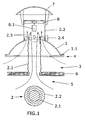
- Figure 1 is the variant with a flue of spherical sector base and/or fixed radial extension of the funnel.
- Figure 2 is a schematic and partial representation of the previous figure, that shows the construction of the internal air shaft for both enclosed spaces, with two air intakes at a different level in the lower one of them, likewise one of the drawings showing the layout in the case of horizontal air evacuation.
- Figure 3 is the variant of flue with cylindrical sector base and adjustable radial extension of the funnel, depending on the equivalent angle of the roof.
- Figure 4 is the controllable forced ventilation variant, without the butterfly and in which the fan is substituted by a motorized raising and closing of the cover.
- the present invention refers to an industrial ventilation apparatus for double enclosed spaces, from among the different air extraction apparatus using natural or forced ventilation; essentially characterised by carrying out the ventilation of the height-separated enclosed spaces, through the common roof, whether with forced and controlled extraction, natural or mixed, based on a spherical or ovoid cylindrical sector base flue (1), whether with rectangular flanges (1.1) or with a projecting section of a large holed metal sheet (1.2), to admit a section of the vent funnel or barrel (2) radially positioned with a ring-shaped circular crown, constructed in position at the intake of the apparatus, so that the ventilation of the enclosed space (3) immediately below the roof (4) is carried out by the ring-shaped duct (2.2) and that of the enclosed space (5) below the false ceiling (6) is carried out by the axial duct (2.1) of the barrel (2), both air passage openings being sized according to the volume of each enclosed space (3) and (5) to be ventilated, with a single apparatus and minimum pressure losses
- At least two air intakes (2.2.1) and (2.2.2) are set up, connecting the consecutive ends of these ducts at their respective bases, with radial rods, these reaching the same different levels (5.1) and (5.2) of the enclosed space (5) below, that break up its stratification.
- the air evacuation opening (1.3) is placed along the generatrices of this sector, with an angle of its axis with respect to the radial plane of the cylinder identical to that of the roof (4), of whatever incline, whether to be previously measured and the opening made in a workshop or whether to be carried out in situ by the installers, according to requirements.
- the flue is finished off with an upper cover (7) preferably of spherical sector, and that may or may not incorporate a plate (7.1) internal to this cover, of discoid configuration, whether truncated-conical or whether corrugated curved, that minimizes air blowback in the cover and that is held at the perimeter by anti-vibration rubber (7.2) in a horizontal "U".
- an upper cover (7) preferably of spherical sector, and that may or may not incorporate a plate (7.1) internal to this cover, of discoid configuration, whether truncated-conical or whether corrugated curved, that minimizes air blowback in the cover and that is held at the perimeter by anti-vibration rubber (7.2) in a horizontal "U".
- the extraction can drive air into one or both of the two enclosed spaces (3) and (5), in this latter case simultaneously into, at least, the levels (5.1) and (5.2).
- a different variant is the one that allows natural ventilation to be extended to both enclosed spaces (3) and (5)and to convert this in controllable, by eliminating the butterfly (2.3) of the axial duct (2.1) and substitution of the extractor (8) motor (8.1), by another motor (9) adjacent to the centre of the cover and designed with an extended axis (9.1) and that incorporates a twin spiral screw (9.2) for multiple positioning of the cover opening (7) or with the closing of this latter directed by a manual remote control or regulation by means of an electronic circuit connected to an anemometer, not shown in the figure.
- the electrical supply (9.3) to the motor (9) is carried out through the interior part of the cover (7), by means of a channelling (7.3) and between this and any bracket of the cover (7) its rotation is prevented, leaving the vertical displacement of the cover (7) between the extreme positions of the twin spiral screw (9.2) as the only possible movement.
- the layout of the air outlet or of its intake can also be horizontally set up, direction, by simple access holing of the opposing part of the construction, main wall and also partitioning of the air chamber. With which the evacuation of the direct heat accumulated in this chamber in the facades oriented South, and everything previously said being valid, except for the change of positioning of the apparatus, is achieved.
Landscapes
- Engineering & Computer Science (AREA)
- Chemical & Material Sciences (AREA)
- Combustion & Propulsion (AREA)
- Mechanical Engineering (AREA)
- General Engineering & Computer Science (AREA)
- Air-Flow Control Members (AREA)
- Organic Low-Molecular-Weight Compounds And Preparation Thereof (AREA)
- Separation, Recovery Or Treatment Of Waste Materials Containing Plastics (AREA)
- Vaporization, Distillation, Condensation, Sublimation, And Cold Traps (AREA)
Claims (8)
- Industrielles Lüftungsgerät für doppelt umschlossene Räume von den verschiedenen Abluftgeräten, die mittels Umluft oder natürlicher direkter Belüftung lüften, das einen Belüftungsschacht (1), eine axiale Leitung (2.1), einen von einem Motor (8.1) betriebenen Extraktor (8) umfasst, , zum Lüften mit einem einzigen Gerät und minimalem Druckverlust, für zwei abgeschlossene Räume, die in der Höhe getrennt sind, durch ein gemeinsames Dach, sei es durch erzwungene oder kontrollierte Absaugung, natürlich oder gemischt, wobei der Belüftungsschacht (1), der eine zylindrische, sphärische oder eiförmige Basis aufweist mit rechteckigen Flanschen (1.1) versehen ist, um einen Abschnitt des Lüftungsschachts oder Laufs (2) aufzunehmen, der radial positioniert mit einer ringförmigen runden Krone, die in einer Position so an dem Geräteeinlass hergestellt ist, dass die Belüftung des umschlossenen Raums (3), der sich unmittelbar unter dem Dach (4) befindet, durch eine ringförmige Leitung (2.2) vollzogen wird und die des umschlossenen Raums (5) unter der abgehängten Decke (6) durch eine axiale Leitung (2.1) des Laufs (2) durchgeführt wird, wobei beide Luftzufuhröffnungen gemäss dem Volumen jedes umschlossenen zu belüftenden Raums (3) und (5) ausgelegt sind und ausserdem die axiale Leitung (2.1) ein motorisiertes (2.4) Drosselventil (2.3) aufweistoder als einen hervorspringenden Abschnitt (1.2) eines langen perforierten Metallabschnitts (1.2),,
- Industrielles Lüftungsgerät für doppelt umschlossene Räume gemäss Anspruch 1, dadurch gekennzeichnet, dass es mindestens zwei zusatzliche Lufteinlässe (2.2.1) und (2.2.2) aufweist, wobei die aufeinanderfolgenden Enden dieser Leitungen durch radiale Stangen an der jeweiligen Basis miteinander verbunden sind; diese Leitungen erreichen verschiedene Niveaus (5.1) und (5.2) des Inneren des unteren Raums (5), die deren Schichtung aufbricht.
- Industrielles Lüftungsgerät für doppelt umschlossene Räume gemäss Anspruch 1, dadurch gekennzeichnet, dass als eine Alternative zu der Konstruktion des radial positionierten Laufs (2) die Öffnung zum Luftablassen (1.3) entlang der Generatoren dieses Bereichs angebracht ist, mit einem Winkel ihrer Achse hinsichtlich der Radialebene des Zylinders, der identisch mit dem des Dachs (4) ist, unabhängig con dessen Neigung.
- Industrielles Lüftungsgerät für doppelt umschlossene Räume gemäss Anspruch 2, dadurch gekennzeichnet, dass als eine Alternative zu dem Absaugen von Luft aus dem Inneren der beiden umschlossenen Räume (3) und (5) die Luft ins Innere von einem oder beiden umschlossenen Räumen (3) und (5) geleitet werden kann und in diesem letzten Fall gleichzeitig mindestens in die Niveaus (5.1) und (5.2).
- Industrielles Lüftungsgerät für doppelt umschlossene Räume gemäss dem Anspruch 3 oder 4, dadurch gekennzeichnet, dass die Auslegung des Luftauslasses oder des Lufteinlasses in waagerechter Richtung durchgeführt wird, durch das einfache Aushöhlen des gegenüberliegenden Teils der Konstruktion, Hauptwand und Aufteilung der Luftkammer.
- Industrielles Lüftungsgerät für doppelt umschlossene Räume gemäss Anspruch 1, dadurch gekennzeichnet, dass der Belüftungsschacht mit einer oberen Abdeckung (7) endet, die vorzugsweise einen sphärischen Querschnitt hat und eine Platte (7.1) im Inneren dieses Deckels umfassen kann, die diskoidal angelegt ist, sei sie stumpf-kegelig oder gewellt gebogen, mit dem Ziel, das Rückblasen der Luft in die Abdeckung zu minimieren, und die umfänglich von einem Antivibrationsgummi (7.2) In einem waagerechten "U" gehalten wird.
- Industrielles Lüftungsgerät für doppelt umschlossene Räume, das einen Belüftungsschacht (1), eine axiale Leitung (2.1), einen von einem Motor (8.1) betriebenen Extraktor (8) umfasst, zum Lüften mit einem einzigen Gerät und minimalem Druckverlust, wobei die doppelt umschlossenen Räume in der Höhe getrennt sind, durch ein gemeinsames Dach, sei es durch erzwungene oder kontrollierte Absaugung, natürlich oder gemischt, wobei der Belüftungsschacht (1), einen Abschnitt des Lüftungsschachts oder Laufs (2) aufnimmt, so dass die Belüftung des umschlossenen Raums (3), der sich unmittelbar unter dem Dach (4) befindet, durch eine ringförmige Leitung (2.2) vollzogen wird und die des umschlossenen Raums (5) unter der abgehängten Decke (6) durch eine axiale Leitung (2.1) des Laufs (2) durchgeführt wird; es umfasst auch einen Motor (9), der an die Mitte der Abdeckung angrenzt und über eine verlängerte Achse (9.1) verfügt und eine Multiposition-Doppelspindelschraube (9.2) umfasst, sei es bei geöffneter oder geschlossener Abdeckung (7), mit manueller Fernbedienung oder Regulierung mittels eines elektronischen Stromkreises, der an ein Anemometer angeschlossen ist.
- Industrielles Lüftungsgerät für doppelt umschlossene Räume gemäss den Ansprüchen 1 und 5, dadurch gekennzeichnet, dass die elektrische Versorgung (9.3) des Motors (9) durch den inneren Bereich der Abdeckung (7) mittels einer Furche (7.3) durchgeführt wird und zwischen dieser und jedweder Klammer der Abdeckung (7) die Rotation dieser verhindert wird, wobei die vertikale Verschiebung der Abdeckung (7) zwischen den Endpositionen der Doppelspindelschraube (9.2) verhindert wird.
Priority Applications (5)
| Application Number | Priority Date | Filing Date | Title |
|---|---|---|---|
| AT02380245T ATE347676T1 (de) | 2002-11-29 | 2002-11-29 | Appareil industriel de ventilation |
| EP02380245A EP1426702B1 (de) | 2002-11-29 | 2002-11-29 | Appareil industriel de ventilation |
| ES02380245T ES2275826T3 (es) | 2002-11-29 | 2002-11-29 | Equipado de ventilacion industrial. |
| DE60216618T DE60216618D1 (de) | 2002-11-29 | 2002-11-29 | Appareil industriel de ventilation |
| PT02380245T PT1426702E (pt) | 2002-11-29 | 2002-11-29 | Aparelho de ventilação industrial |
Applications Claiming Priority (1)
| Application Number | Priority Date | Filing Date | Title |
|---|---|---|---|
| EP02380245A EP1426702B1 (de) | 2002-11-29 | 2002-11-29 | Appareil industriel de ventilation |
Publications (2)
| Publication Number | Publication Date |
|---|---|
| EP1426702A1 EP1426702A1 (de) | 2004-06-09 |
| EP1426702B1 true EP1426702B1 (de) | 2006-12-06 |
Family
ID=32309507
Family Applications (1)
| Application Number | Title | Priority Date | Filing Date |
|---|---|---|---|
| EP02380245A Expired - Lifetime EP1426702B1 (de) | 2002-11-29 | 2002-11-29 | Appareil industriel de ventilation |
Country Status (5)
| Country | Link |
|---|---|
| EP (1) | EP1426702B1 (de) |
| AT (1) | ATE347676T1 (de) |
| DE (1) | DE60216618D1 (de) |
| ES (1) | ES2275826T3 (de) |
| PT (1) | PT1426702E (de) |
Cited By (1)
| Publication number | Priority date | Publication date | Assignee | Title |
|---|---|---|---|---|
| US9933182B2 (en) | 2012-09-07 | 2018-04-03 | Csr Building Products Limited | System for optimising an environmental parameter of an enclosed space |
Families Citing this family (2)
| Publication number | Priority date | Publication date | Assignee | Title |
|---|---|---|---|---|
| AU2013313028B2 (en) * | 2012-09-07 | 2017-04-13 | Csr Building Products Limited | Airflow valve |
| CN112879071A (zh) * | 2021-02-19 | 2021-06-01 | 沈锋 | 一种隧道通风用可调节组合风阀 |
Family Cites Families (4)
| Publication number | Priority date | Publication date | Assignee | Title |
|---|---|---|---|---|
| US2569319A (en) * | 1948-07-06 | 1951-09-25 | Oliver J Krug | Ventilating apparatus |
| US2700331A (en) * | 1951-04-16 | 1955-01-25 | Bryce H Miller | Air circulating unit |
| DE20021051U1 (de) * | 2000-12-12 | 2002-04-11 | Klöber, Johannes, 58256 Ennepetal | Lüftungsrohr |
| DE20109561U1 (de) * | 2001-06-07 | 2001-08-30 | Fleck, Oskar, 45711 Datteln | Rohrkanal mit Auffangrinne für Kanalkondensate |
-
2002
- 2002-11-29 EP EP02380245A patent/EP1426702B1/de not_active Expired - Lifetime
- 2002-11-29 DE DE60216618T patent/DE60216618D1/de not_active Expired - Lifetime
- 2002-11-29 ES ES02380245T patent/ES2275826T3/es not_active Expired - Lifetime
- 2002-11-29 AT AT02380245T patent/ATE347676T1/de not_active IP Right Cessation
- 2002-11-29 PT PT02380245T patent/PT1426702E/pt unknown
Cited By (1)
| Publication number | Priority date | Publication date | Assignee | Title |
|---|---|---|---|---|
| US9933182B2 (en) | 2012-09-07 | 2018-04-03 | Csr Building Products Limited | System for optimising an environmental parameter of an enclosed space |
Also Published As
| Publication number | Publication date |
|---|---|
| EP1426702A1 (de) | 2004-06-09 |
| PT1426702E (pt) | 2007-02-28 |
| DE60216618D1 (de) | 2007-01-18 |
| ATE347676T1 (de) | 2006-12-15 |
| ES2275826T3 (es) | 2007-06-16 |
Similar Documents
| Publication | Publication Date | Title |
|---|---|---|
| US4759272A (en) | Ventilator | |
| US7682231B2 (en) | Exhaust fan assembly | |
| US7320636B2 (en) | Exhaust fan assembly having flexible coupling | |
| US3211080A (en) | Draft control unit | |
| US20050159101A1 (en) | Pivotal direct drive motor for exhaust assembly | |
| CN110056951B (zh) | 一种出风装置、空调室内机及空调 | |
| US5697226A (en) | Self-contained air-conditioner of the wall-mounted type | |
| KR101055166B1 (ko) | 온도센서 및 압력센서를 이용한 공동 주택 냉난방 급배기 시스템 유니트용 전동 디퓨져 | |
| US2885948A (en) | Daylight dome ventilator construction | |
| US3302551A (en) | Ventilator | |
| US6159093A (en) | Powered exhaust fan | |
| EP1426702A1 (de) | Appareil industriel de ventilation | |
| CN100504220C (zh) | 具有弹性联结器的排气风扇组合件 | |
| KR100943859B1 (ko) | 풍량조절구가 구비된 바닥 공조용 취출구 | |
| KR100479390B1 (ko) | 벤틸레이터 | |
| JP7186240B2 (ja) | 空調システム及びその制御方法 | |
| CN105650798A (zh) | 具有新风功能的换气装置 | |
| KR20110009752U (ko) | 전동 디퓨저 | |
| US7074121B2 (en) | Homogeneous vent cap | |
| KR20100010441U (ko) | 전동 디퓨저 | |
| US925252A (en) | Ventilator. | |
| CN214835166U (zh) | 外置式通风机房 | |
| BE1028447B1 (nl) | Inrichting voor luchttoevoer en rookgasafvoer voor gashaarden | |
| US20080139104A1 (en) | Heat exchange system | |
| SK9942000A3 (en) | Ventilating unit |
Legal Events
| Date | Code | Title | Description |
|---|---|---|---|
| PUAI | Public reference made under article 153(3) epc to a published international application that has entered the european phase |
Free format text: ORIGINAL CODE: 0009012 |
|
| AK | Designated contracting states |
Kind code of ref document: A1 Designated state(s): AT BE BG CH CY CZ DE DK EE ES FI FR GB GR IE IT LI LU MC NL PT SE SK TR |
|
| AX | Request for extension of the european patent |
Extension state: AL LT LV MK RO SI |
|
| AKX | Designation fees paid | ||
| REG | Reference to a national code |
Ref country code: DE Ref legal event code: 8566 |
|
| RBV | Designated contracting states (corrected) |
Designated state(s): AT BE BG CH CY CZ DE DK EE ES FI FR GB GR IE IT LI LU MC NL PT SE SK TR |
|
| 17P | Request for examination filed |
Effective date: 20050221 |
|
| GRAP | Despatch of communication of intention to grant a patent |
Free format text: ORIGINAL CODE: EPIDOSNIGR1 |
|
| GRAS | Grant fee paid |
Free format text: ORIGINAL CODE: EPIDOSNIGR3 |
|
| GRAA | (expected) grant |
Free format text: ORIGINAL CODE: 0009210 |
|
| AK | Designated contracting states |
Kind code of ref document: B1 Designated state(s): AT BE BG CH CY CZ DE DK EE ES FI FR GB GR IE IT LI LU MC NL PT SE SK TR |
|
| PG25 | Lapsed in a contracting state [announced via postgrant information from national office to epo] |
Ref country code: SK Free format text: LAPSE BECAUSE OF FAILURE TO SUBMIT A TRANSLATION OF THE DESCRIPTION OR TO PAY THE FEE WITHIN THE PRESCRIBED TIME-LIMIT Effective date: 20061206 Ref country code: LI Free format text: LAPSE BECAUSE OF FAILURE TO SUBMIT A TRANSLATION OF THE DESCRIPTION OR TO PAY THE FEE WITHIN THE PRESCRIBED TIME-LIMIT Effective date: 20061206 Ref country code: NL Free format text: LAPSE BECAUSE OF FAILURE TO SUBMIT A TRANSLATION OF THE DESCRIPTION OR TO PAY THE FEE WITHIN THE PRESCRIBED TIME-LIMIT Effective date: 20061206 Ref country code: CZ Free format text: LAPSE BECAUSE OF FAILURE TO SUBMIT A TRANSLATION OF THE DESCRIPTION OR TO PAY THE FEE WITHIN THE PRESCRIBED TIME-LIMIT Effective date: 20061206 Ref country code: CH Free format text: LAPSE BECAUSE OF FAILURE TO SUBMIT A TRANSLATION OF THE DESCRIPTION OR TO PAY THE FEE WITHIN THE PRESCRIBED TIME-LIMIT Effective date: 20061206 Ref country code: AT Free format text: LAPSE BECAUSE OF FAILURE TO SUBMIT A TRANSLATION OF THE DESCRIPTION OR TO PAY THE FEE WITHIN THE PRESCRIBED TIME-LIMIT Effective date: 20061206 Ref country code: BE Free format text: LAPSE BECAUSE OF FAILURE TO SUBMIT A TRANSLATION OF THE DESCRIPTION OR TO PAY THE FEE WITHIN THE PRESCRIBED TIME-LIMIT Effective date: 20061206 Ref country code: FI Free format text: LAPSE BECAUSE OF FAILURE TO SUBMIT A TRANSLATION OF THE DESCRIPTION OR TO PAY THE FEE WITHIN THE PRESCRIBED TIME-LIMIT Effective date: 20061206 |
|
| REG | Reference to a national code |
Ref country code: GB Ref legal event code: FG4D |
|
| REG | Reference to a national code |
Ref country code: CH Ref legal event code: EP |
|
| REG | Reference to a national code |
Ref country code: IE Ref legal event code: FG4D |
|
| REF | Corresponds to: |
Ref document number: 60216618 Country of ref document: DE Date of ref document: 20070118 Kind code of ref document: P |
|
| REG | Reference to a national code |
Ref country code: PT Ref legal event code: SC4A Free format text: AVAILABILITY OF NATIONAL TRANSLATION Effective date: 20070221 |
|
| PG25 | Lapsed in a contracting state [announced via postgrant information from national office to epo] |
Ref country code: BG Free format text: LAPSE BECAUSE OF FAILURE TO SUBMIT A TRANSLATION OF THE DESCRIPTION OR TO PAY THE FEE WITHIN THE PRESCRIBED TIME-LIMIT Effective date: 20070306 Ref country code: SE Free format text: LAPSE BECAUSE OF FAILURE TO SUBMIT A TRANSLATION OF THE DESCRIPTION OR TO PAY THE FEE WITHIN THE PRESCRIBED TIME-LIMIT Effective date: 20070306 |
|
| PG25 | Lapsed in a contracting state [announced via postgrant information from national office to epo] |
Ref country code: DE Free format text: LAPSE BECAUSE OF FAILURE TO SUBMIT A TRANSLATION OF THE DESCRIPTION OR TO PAY THE FEE WITHIN THE PRESCRIBED TIME-LIMIT Effective date: 20070307 |
|
| NLV1 | Nl: lapsed or annulled due to failure to fulfill the requirements of art. 29p and 29m of the patents act | ||
| REG | Reference to a national code |
Ref country code: CH Ref legal event code: PL |
|
| REG | Reference to a national code |
Ref country code: ES Ref legal event code: FG2A Ref document number: 2275826 Country of ref document: ES Kind code of ref document: T3 |
|
| ET | Fr: translation filed | ||
| PLBE | No opposition filed within time limit |
Free format text: ORIGINAL CODE: 0009261 |
|
| STAA | Information on the status of an ep patent application or granted ep patent |
Free format text: STATUS: NO OPPOSITION FILED WITHIN TIME LIMIT |
|
| 26N | No opposition filed |
Effective date: 20070907 |
|
| PG25 | Lapsed in a contracting state [announced via postgrant information from national office to epo] |
Ref country code: GR Free format text: LAPSE BECAUSE OF FAILURE TO SUBMIT A TRANSLATION OF THE DESCRIPTION OR TO PAY THE FEE WITHIN THE PRESCRIBED TIME-LIMIT Effective date: 20070307 |
|
| PG25 | Lapsed in a contracting state [announced via postgrant information from national office to epo] |
Ref country code: MC Free format text: LAPSE BECAUSE OF NON-PAYMENT OF DUE FEES Effective date: 20071130 |
|
| GBPC | Gb: european patent ceased through non-payment of renewal fee |
Effective date: 20071129 |
|
| PG25 | Lapsed in a contracting state [announced via postgrant information from national office to epo] |
Ref country code: IE Free format text: LAPSE BECAUSE OF NON-PAYMENT OF DUE FEES Effective date: 20071129 |
|
| PG25 | Lapsed in a contracting state [announced via postgrant information from national office to epo] |
Ref country code: GB Free format text: LAPSE BECAUSE OF NON-PAYMENT OF DUE FEES Effective date: 20071129 |
|
| PG25 | Lapsed in a contracting state [announced via postgrant information from national office to epo] |
Ref country code: EE Free format text: LAPSE BECAUSE OF FAILURE TO SUBMIT A TRANSLATION OF THE DESCRIPTION OR TO PAY THE FEE WITHIN THE PRESCRIBED TIME-LIMIT Effective date: 20061206 |
|
| PGFP | Annual fee paid to national office [announced via postgrant information from national office to epo] |
Ref country code: TR Payment date: 20080826 Year of fee payment: 7 |
|
| PG25 | Lapsed in a contracting state [announced via postgrant information from national office to epo] |
Ref country code: CY Free format text: LAPSE BECAUSE OF FAILURE TO SUBMIT A TRANSLATION OF THE DESCRIPTION OR TO PAY THE FEE WITHIN THE PRESCRIBED TIME-LIMIT Effective date: 20061206 Ref country code: DK Free format text: LAPSE BECAUSE OF FAILURE TO SUBMIT A TRANSLATION OF THE DESCRIPTION OR TO PAY THE FEE WITHIN THE PRESCRIBED TIME-LIMIT Effective date: 20070306 Ref country code: LU Free format text: LAPSE BECAUSE OF NON-PAYMENT OF DUE FEES Effective date: 20071129 |
|
| PGFP | Annual fee paid to national office [announced via postgrant information from national office to epo] |
Ref country code: PT Payment date: 20090930 Year of fee payment: 8 |
|
| PGFP | Annual fee paid to national office [announced via postgrant information from national office to epo] |
Ref country code: FR Payment date: 20091113 Year of fee payment: 8 Ref country code: IT Payment date: 20091127 Year of fee payment: 8 |
|
| REG | Reference to a national code |
Ref country code: PT Ref legal event code: MM4A Free format text: LAPSE DUE TO NON-PAYMENT OF FEES Effective date: 20110530 |
|
| PG25 | Lapsed in a contracting state [announced via postgrant information from national office to epo] |
Ref country code: PT Free format text: LAPSE BECAUSE OF NON-PAYMENT OF DUE FEES Effective date: 20110530 |
|
| REG | Reference to a national code |
Ref country code: FR Ref legal event code: ST Effective date: 20110801 |
|
| PG25 | Lapsed in a contracting state [announced via postgrant information from national office to epo] |
Ref country code: FR Free format text: LAPSE BECAUSE OF NON-PAYMENT OF DUE FEES Effective date: 20101130 |
|
| PG25 | Lapsed in a contracting state [announced via postgrant information from national office to epo] |
Ref country code: IT Free format text: LAPSE BECAUSE OF NON-PAYMENT OF DUE FEES Effective date: 20101129 |
|
| PG25 | Lapsed in a contracting state [announced via postgrant information from national office to epo] |
Ref country code: TR Free format text: LAPSE BECAUSE OF NON-PAYMENT OF DUE FEES Effective date: 20091129 |
|
| PGFP | Annual fee paid to national office [announced via postgrant information from national office to epo] |
Ref country code: ES Payment date: 20211202 Year of fee payment: 20 |
|
| REG | Reference to a national code |
Ref country code: ES Ref legal event code: FD2A Effective date: 20230426 |
|
| PG25 | Lapsed in a contracting state [announced via postgrant information from national office to epo] |
Ref country code: ES Free format text: LAPSE BECAUSE OF EXPIRATION OF PROTECTION Effective date: 20221130 |