EP1426706B1 - Lüftungsgerät - Google Patents
Lüftungsgerät Download PDFInfo
- Publication number
- EP1426706B1 EP1426706B1 EP03025179A EP03025179A EP1426706B1 EP 1426706 B1 EP1426706 B1 EP 1426706B1 EP 03025179 A EP03025179 A EP 03025179A EP 03025179 A EP03025179 A EP 03025179A EP 1426706 B1 EP1426706 B1 EP 1426706B1
- Authority
- EP
- European Patent Office
- Prior art keywords
- convector
- air
- duct
- blower
- ventilation device
- Prior art date
- Legal status (The legal status is an assumption and is not a legal conclusion. Google has not performed a legal analysis and makes no representation as to the accuracy of the status listed.)
- Expired - Lifetime
Links
- 238000009423 ventilation Methods 0.000 title claims description 54
- 238000001816 cooling Methods 0.000 claims abstract description 14
- 238000010438 heat treatment Methods 0.000 claims description 12
- 238000009434 installation Methods 0.000 claims description 8
- 230000001105 regulatory effect Effects 0.000 claims description 4
- 239000003570 air Substances 0.000 claims 19
- 238000011144 upstream manufacturing Methods 0.000 claims 2
- 239000012080 ambient air Substances 0.000 claims 1
- 239000011810 insulating material Substances 0.000 description 7
- 238000011084 recovery Methods 0.000 description 6
- 230000001174 ascending effect Effects 0.000 description 5
- 238000010276 construction Methods 0.000 description 5
- 239000004020 conductor Substances 0.000 description 4
- 238000013461 design Methods 0.000 description 3
- 230000002349 favourable effect Effects 0.000 description 3
- 238000009413 insulation Methods 0.000 description 3
- 238000000926 separation method Methods 0.000 description 3
- 238000009530 blood pressure measurement Methods 0.000 description 2
- 230000000694 effects Effects 0.000 description 2
- 241000446313 Lamella Species 0.000 description 1
- 238000010521 absorption reaction Methods 0.000 description 1
- 238000005273 aeration Methods 0.000 description 1
- 239000002826 coolant Substances 0.000 description 1
- 230000001419 dependent effect Effects 0.000 description 1
- 238000011161 development Methods 0.000 description 1
- 230000018109 developmental process Effects 0.000 description 1
- 238000006073 displacement reaction Methods 0.000 description 1
- 238000001914 filtration Methods 0.000 description 1
- 239000007788 liquid Substances 0.000 description 1
- 238000005259 measurement Methods 0.000 description 1
- 238000005399 mechanical ventilation Methods 0.000 description 1
- 238000012544 monitoring process Methods 0.000 description 1
- ORQBXQOJMQIAOY-UHFFFAOYSA-N nobelium Chemical compound [No] ORQBXQOJMQIAOY-UHFFFAOYSA-N 0.000 description 1
- 238000012856 packing Methods 0.000 description 1
- 238000005192 partition Methods 0.000 description 1
- 230000000630 rising effect Effects 0.000 description 1
- 238000012360 testing method Methods 0.000 description 1
- XLYOFNOQVPJJNP-UHFFFAOYSA-N water Substances O XLYOFNOQVPJJNP-UHFFFAOYSA-N 0.000 description 1
Images

Classifications
-
- F—MECHANICAL ENGINEERING; LIGHTING; HEATING; WEAPONS; BLASTING
- F24—HEATING; RANGES; VENTILATING
- F24F—AIR-CONDITIONING; AIR-HUMIDIFICATION; VENTILATION; USE OF AIR CURRENTS FOR SCREENING
- F24F12/00—Use of energy recovery systems in air conditioning, ventilation or screening
- F24F12/001—Use of energy recovery systems in air conditioning, ventilation or screening with heat-exchange between supplied and exhausted air
- F24F12/006—Use of energy recovery systems in air conditioning, ventilation or screening with heat-exchange between supplied and exhausted air using an air-to-air heat exchanger
-
- F—MECHANICAL ENGINEERING; LIGHTING; HEATING; WEAPONS; BLASTING
- F24—HEATING; RANGES; VENTILATING
- F24F—AIR-CONDITIONING; AIR-HUMIDIFICATION; VENTILATION; USE OF AIR CURRENTS FOR SCREENING
- F24F7/00—Ventilation
- F24F7/04—Ventilation with ducting systems, e.g. by double walls; with natural circulation
- F24F7/06—Ventilation with ducting systems, e.g. by double walls; with natural circulation with forced air circulation, e.g. by fan positioning of a ventilator in or against a conduit
- F24F7/08—Ventilation with ducting systems, e.g. by double walls; with natural circulation with forced air circulation, e.g. by fan positioning of a ventilator in or against a conduit with separate ducts for supplied and exhausted air with provisions for reversal of the input and output systems
-
- F—MECHANICAL ENGINEERING; LIGHTING; HEATING; WEAPONS; BLASTING
- F24—HEATING; RANGES; VENTILATING
- F24F—AIR-CONDITIONING; AIR-HUMIDIFICATION; VENTILATION; USE OF AIR CURRENTS FOR SCREENING
- F24F11/00—Control or safety arrangements
- F24F11/70—Control systems characterised by their outputs; Constructional details thereof
- F24F11/72—Control systems characterised by their outputs; Constructional details thereof for controlling the supply of treated air, e.g. its pressure
- F24F11/74—Control systems characterised by their outputs; Constructional details thereof for controlling the supply of treated air, e.g. its pressure for controlling air flow rate or air velocity
- F24F11/75—Control systems characterised by their outputs; Constructional details thereof for controlling the supply of treated air, e.g. its pressure for controlling air flow rate or air velocity for maintaining constant air flow rate or air velocity
-
- F—MECHANICAL ENGINEERING; LIGHTING; HEATING; WEAPONS; BLASTING
- F24—HEATING; RANGES; VENTILATING
- F24F—AIR-CONDITIONING; AIR-HUMIDIFICATION; VENTILATION; USE OF AIR CURRENTS FOR SCREENING
- F24F11/00—Control or safety arrangements
- F24F11/70—Control systems characterised by their outputs; Constructional details thereof
- F24F11/72—Control systems characterised by their outputs; Constructional details thereof for controlling the supply of treated air, e.g. its pressure
- F24F11/74—Control systems characterised by their outputs; Constructional details thereof for controlling the supply of treated air, e.g. its pressure for controlling air flow rate or air velocity
- F24F11/77—Control systems characterised by their outputs; Constructional details thereof for controlling the supply of treated air, e.g. its pressure for controlling air flow rate or air velocity by controlling the speed of ventilators
-
- F—MECHANICAL ENGINEERING; LIGHTING; HEATING; WEAPONS; BLASTING
- F24—HEATING; RANGES; VENTILATING
- F24F—AIR-CONDITIONING; AIR-HUMIDIFICATION; VENTILATION; USE OF AIR CURRENTS FOR SCREENING
- F24F12/00—Use of energy recovery systems in air conditioning, ventilation or screening
- F24F12/001—Use of energy recovery systems in air conditioning, ventilation or screening with heat-exchange between supplied and exhausted air
- F24F2012/007—Use of energy recovery systems in air conditioning, ventilation or screening with heat-exchange between supplied and exhausted air using a by-pass for bypassing the heat-exchanger
-
- F—MECHANICAL ENGINEERING; LIGHTING; HEATING; WEAPONS; BLASTING
- F24—HEATING; RANGES; VENTILATING
- F24F—AIR-CONDITIONING; AIR-HUMIDIFICATION; VENTILATION; USE OF AIR CURRENTS FOR SCREENING
- F24F2110/00—Control inputs relating to air properties
- F24F2110/40—Pressure, e.g. wind pressure
-
- F—MECHANICAL ENGINEERING; LIGHTING; HEATING; WEAPONS; BLASTING
- F24—HEATING; RANGES; VENTILATING
- F24F—AIR-CONDITIONING; AIR-HUMIDIFICATION; VENTILATION; USE OF AIR CURRENTS FOR SCREENING
- F24F2221/00—Details or features not otherwise provided for
- F24F2221/17—Details or features not otherwise provided for mounted in a wall
-
- Y—GENERAL TAGGING OF NEW TECHNOLOGICAL DEVELOPMENTS; GENERAL TAGGING OF CROSS-SECTIONAL TECHNOLOGIES SPANNING OVER SEVERAL SECTIONS OF THE IPC; TECHNICAL SUBJECTS COVERED BY FORMER USPC CROSS-REFERENCE ART COLLECTIONS [XRACs] AND DIGESTS
- Y02—TECHNOLOGIES OR APPLICATIONS FOR MITIGATION OR ADAPTATION AGAINST CLIMATE CHANGE
- Y02B—CLIMATE CHANGE MITIGATION TECHNOLOGIES RELATED TO BUILDINGS, e.g. HOUSING, HOUSE APPLIANCES OR RELATED END-USER APPLICATIONS
- Y02B30/00—Energy efficient heating, ventilation or air conditioning [HVAC]
- Y02B30/56—Heat recovery units
-
- Y—GENERAL TAGGING OF NEW TECHNOLOGICAL DEVELOPMENTS; GENERAL TAGGING OF CROSS-SECTIONAL TECHNOLOGIES SPANNING OVER SEVERAL SECTIONS OF THE IPC; TECHNICAL SUBJECTS COVERED BY FORMER USPC CROSS-REFERENCE ART COLLECTIONS [XRACs] AND DIGESTS
- Y02—TECHNOLOGIES OR APPLICATIONS FOR MITIGATION OR ADAPTATION AGAINST CLIMATE CHANGE
- Y02B—CLIMATE CHANGE MITIGATION TECHNOLOGIES RELATED TO BUILDINGS, e.g. HOUSING, HOUSE APPLIANCES OR RELATED END-USER APPLICATIONS
- Y02B30/00—Energy efficient heating, ventilation or air conditioning [HVAC]
- Y02B30/70—Efficient control or regulation technologies, e.g. for control of refrigerant flow, motor or heating
Definitions
- the invention relates to a ventilation device according to the features specified in the preamble of claim 1.
- Such a ventilation device which contains in a housing at least one supply air fan, a convector and separate channels for air duct, wherein the housing has a space outside inlet opening for the supply air and an interior of a building associated discharge opening.
- the ventilation unit can be installed in a façade or window construction.
- the ventilation device includes an exhaust fan and a channel for the exhaust air, which are sucked in by a said interior facing the intake opening of the housing and can flow out through an exhaust port of the housing to the outside.
- the unit includes a heat exchanger to supply the heat contained in the exhaust air to the supply air.
- the convector is flowed through by a particular liquid medium and optionally as a heating element or cooling element according to the supplied with the medium of energy or heat and the predetermined mode. If the named interior of the building is to be heated by means of the convector with appropriate heat input, then in particular the supply air blower must be in operation to control the supply air or, if the position of the dampers influencing the air flow, the air flow through or through the flap Conduct convector.
- the invention has the object, the ventilation device of the type mentioned with a small design effort to the effect that the convector is effectively usable according to preselected modes.
- the ventilation unit should be functional in a compact design for the desired mode of operation.
- the ventilation device should be able to be used in a simple manner and with little effort for different installation situations.
- the proposed ventilation device is characterized by a compact and functional design and allows due to the movable arrangement of the convector in a first position of a forced air duct over the convector, especially when the fan is switched on, and in a second position of the convector free convection, preferably when the blower is switched off.
- the convector is connected via suitable connections with flexibly or movably formed lines through which a medium, such as water, can be supplied to supply heating or cooling energy as required.
- the interior of a building associated or room side arranged movable convector is connected to the device housing and / or associated with this, that during operation no air leakage.
- the convector a condensate tray is readjusted, if necessary, to dehumidify the air to be supplied to the room targeted and remove condensate condensate controlled.
- the convector is mounted or arranged in an advantageous manner in a heat and / or Schalldämmpackung.
- the convector is arranged on a base plate below the ventilation unit.
- the base plate means are provided for the movable mounting of the convector, which means are preferably designed as a rotary joint, guide rails or the like. These means allow movement of the convector with the fan off in the direction of the room, thus allowing free convection.
- This mode is always advantageous when no fresh air rate is required.
- the ones for the movement, especially the Folding out and folding the convector provided drive unit, which is preferably designed as an actuator, is advantageously arranged laterally on the convector frame and / or a base plate.
- a temperature sensor for measuring the temperature of the outflowing air is provided to supply a temperature corresponding measurement variable of a control and control unit.
- a control and control unit can be used to control, control and monitor all components mounted in the ventilation unit, such as blowers, closure elements or flaps of the ducts, the drive unit of the convector and the like. This is particularly useful if in a building a variety of decentralized ventilation equipment is mounted and they should not be opened for functional testing.
- the control and regulation unit in a preferred manner, for example via the Internet or data line, remote monitoring of the decentralized ventilation device or ventilation components can also take place.
- a drive unit for the movement of the convector, a drive unit is provided, by means of which the convector is movable to the desired position.
- the convector is advantageously arranged in the region of the outflow opening, in particular below it.
- the convector can be integrated directly into the housing within the scope of the invention.
- the pivotable mounting of the convector, in particular on its underside, has proved to be particularly useful, so that the convector is flush with the rear wall of the housing depending on the assumed operating position or is open in free convection.
- the ventilation unit on the underside in particular in the region of the outflow opening, preferably closed automatically, so that the ventilation unit adjusts a standing column of air, whereby the greatest possible heat and sound protection is effected via the ventilation device according to the invention.
- the convector is either designed for heating or cooling, expedient in a one-, two-, three- or four-conductor system.
- a decentralized active and self-contained suction and pressure controlled ventilation unit with heating and cooling facility is created.
- the ventilation unit is for the Installation in a facade or window construction designed as a floor, parapet, ceiling or Paneel réelle.
- the ventilation unit contains a supply, exhaust and recirculation unit, expedient with additional possible fresh air intake, and that supported by blower.
- an integrated energy recovery with a heat exchanger in particular a cross-countercurrent heat exchanger.
- the energy recovery is formed with a moisture return, wherein moisture is supplied to the exhaust air of the fresh air. All airways or channels are consistently separated, and air mixing in the device does not take place.
- the channels are designed as heat and / or sound absorption channels, and the housing is thermally separated.
- the installation can be made visible or hidden from the outside.
- the air outlet or the room-side air inlet is provided as low as possible for generating a source ventilation in an advantageous manner.
- a tangential air outlet may be provided on the room side.
- the exhaust air is supplied according to the to be observed boundary conditions, installation situations or the like of the ventilation unit from above, from the front or side.
- the intended for heating and / or cooling convector is advantageously formed in one-, two-, three- or four-conductor system, with an embodiment with or without condensate tray can be provided as needed.
- the filter option from EU 2 to pollen filters can be provided as needed.
- the ventilation device includes an integrated control of the blower, in particular its speed to independently depending on a wind suction and / or wind pressure, for example on the outer facade, the fan to guide it, so as to transport constant volume flows and constant heating and / or to set cooling capacities.
- a differential pressure measurement is advantageously provided before and / or after at least one blower, expediently all blowers of the ventilation device.
- a logic unit which is preferably integrated in the control and regulation unit, an at least approximately constant volume flow within a predeterminable pressure window automatically adjusted.
- supply air fan and the exhaust fan are expediently coupled to one another in such a way, in particular via the logic unit or the control unit, that at least approximately under the two fans set the same volume flows. Because the one will promote a higher volume flow in Sog than the other, and vice versa when pressure.
- the decentralized ventilation unit which is arranged in a window or facade construction, contains a thermally separated housing.
- the air passages or flow channels and also substantially the entire interior of the housing are lined with a special insulating material.
- the air paths or flow channels are provided with a special, acoustically transparent surface.
- a heat exchanger which is designed in particular as a cross-flow plate heat exchanger, the energy contained in the exhaust air is indirectly fed to the fresh air for energy recovery.
- cooler exhaust air from the room can cool energetically favorably the supply air supplied from the outside and, in the winter, energetically heat the supply air or fresh air.
- a bypass control for the building energetically favorable operation is possible to bypass in those operating cases in which no energy recovery is desired, this or the heat exchanger.
- This mode which is referred to as an internal heat exchanger bypass, is then specified when the fresh air is cooler than the room air and when the room with the fresh air to be cooled energetically favorable, in particular for night cooling or in transitional periods.
- the ventilation device is characterized by the fact that for the resulting condensate at the inner heat exchanger, an indirect humid return is provided and thus a discharge of the condensate is not required by a so-called condensate line.
- the cross-plate heat exchanger is formed with its substantially vertically arranged plates open in each case in the ducts for the exhaust air down, so that the resulting condensate in a arranged underneath Condensate cup can get or drip.
- This inner condensate tray advantageously contains an element for the airtight conduction of the collected condensate into the region of the supply air channel, in particular a nonwoven intended for this application.
- Air mixing between supply air and exhaust air can not take place due to the separation by means of the fleece, preferably in combination with applied webs.
- the accumulating condensate is thus indirectly supplied to the dryer supply air, so that the supply air supplies the condensate so absorbed to the room.
- the separate Zu poverty- and exhaust air paths are closed by means of a suitable device with shut-off fans, preferably via the control and / or control unit, so that no unwanted loading, Ent- or re-aeration can take place via the ventilation unit.
- the ventilation unit includes a functional unit, which is designed only as a recirculation unit or as a recirculation unit with additional Frischluftansaugung and by means of which an increased heating or cooling power requirement is ensured up to a maximum possible.
- room air is additionally extracted via a ventilation duct integrated into the air duct, as described above, heat- and sound-insulated air duct and fed to a mixed air chamber in front of the room-side convector.
- This integrated air circulation unit is additionally distinguished by the fact that an automatic flap or the like is provided, which prevents the backflow when the circulating air blower is switched off via its air duct, which opens into the said mixed air chamber.
- fresh air can be sucked in by opening a continuously controlled flap or the like. Due to the constantly regulated recirculating-air fresh-air flap or the like, the fresh-air rate can thus be substantially increased up to a maximum desired or predetermined value corresponding to the maximum air output of the recirculating-air unit.
- the ventilation device includes a thermally separated housing 2 with a clamping frame 4, which is preferably formed circumferentially and / or four-sided for the purpose of connection to a facade or window construction or the like.
- the ventilation unit can be used as a floor parapet ceiling or panel unit.
- the housing is inside substantially completely provided with insulating material 6 for thermal and / or acoustic insulation.
- the built-in ventilation unit is located between an outside space 7 and a room 8 of a building. Facing the room 8, the ventilation unit includes an inner panel 10 and the outer space 7 facing on the outside outer weather-protection slats 12 or the like.
- the housing 2 contains on the outside of an inflow opening 14 for fresh air or supply air, which is sucked in accordance with the arrows 16 by a supply air blower 18 through a supply air duct 20, 22 and conveyed to a space inside the outflow opening 23.
- a supply air filter 24 is arranged in the supply air duct 20, which allows air filtering, preferably from EU 2 up to pollen filter.
- an exhaust duct 26, 28 is provided for discharged from the space 8 exhaust air according to the arrows 30.
- the exhaust air 30 is sucked in by an upper opening 32 of the housing 2 and an opening 32 associated filter 34 by means of a arranged inside the housing exhaust fan 36 to over the drawing downwardly adjacent channel 28 through an outflow opening 38 to the outside reach.
- a heat exchanger 40 is provided at least approximately in the middle of the housing 2, which is the preferred way as a cross-flow plate heat exchanger is formed and allows energy recovery from the exhaust air for the supply air.
- a collecting tray 44 is arranged for accumulating condensate.
- the collecting tray 44 is an especially designed as a nonwoven element 45 for airtight pipe of the collected condensed air from the exhaust condensate in the region of the supply air channel 20.
- the heat exchanger 40 is formed with its substantially vertically arranged plates such that its shafts are open for the exhaust air down and thus accumulating condensate can get into the arranged below drip tray 44 or dripping.
- the condensate enters the region of the supply air channel 20 behind the inflow opening 14.
- the housing 2 contains in the region of the opening 32, a further fan 46, by means of which circulating air according to arrow 48 can be sucked through the opening 32.
- the further fan 46 is arranged behind a further opening 50 in the housing 2 or its outer wall 39, whereby additional circulating air can be sucked in as indicated by arrow 52 through the further opening 50.
- a closure element 54 which is designed in particular as a pivotable flap, the further opening 50 can be closed or released according to the selectable operating mode.
- a not shown here, preferably electric drive is provided, which can be controlled by the aforementioned control and control unit.
- inflow opening 14 for supply air is associated with a closure element 56, which is also designed as a pivotable and operable by means of a drive flap.
- closure element 56 which is also designed as a pivotable and operable by means of a drive flap.
- closure element 58 which is preferably designed as a flap and which can be actuated via a drive and can be activated via the control and regulation unit in accordance with the selected operating mode.
- At least one fan is regulated as a function of the wind suction and the wind pressure.
- the invention of the Suction and wind pressure-dependent control will be explained below in connection with the supply air blower 18 and is provided analogously to the other blowers 36 and 46.
- a first sensor 60 and after the supply air blower 18, a second sensor 61 in the supply air duct 22, 22 is arranged in the flow direction of the air in front of the supply air blower 18.
- a first sensor 60 and after the supply air blower 18, a second sensor 61 in the supply air duct 22, 22 is arranged.
- the sensors 60, 61 takes place a differential pressure measurement and a corresponding signal is supplied in particular a logic element of the control and control unit for speed control of the supply air blower 18.
- an at least approximately constant volume flow preferably within a predetermined pressure window or pressure range, automatically adjusted.
- the supply air blower 18 is guided independently of the wind suction and / or wind pressure prevailing in the outer space 7 or on the facade, and a constant heating and / or cooling capacity is ensured on account of the substantially constant volumetric flow.
- a further sensor 61 may be arranged in the region of an outlet opening 64, in particular below the convector 62, for speed control, in particular of the supply air blower 18.
- a convector 62 is arranged movably.
- a base plate 63 is provided, wherein below the convector 62, the outlet opening 64 is present.
- the supply air conveyed by the supply air blower 18 flows from top to bottom through the convector 62 and passes through the outlet opening 64 into the space 8.
- a second position of the convector is indicated, which hereby at least partially moved in the direction of the space 8, and that is pivoted about an axis of rotation 68.
- the convector 62 is mounted on the base plate 63 by means of a bearing about the axis of rotation 68 pivotally.
- the convector In the second position, in which the outflow opening 23 is preferably closed automatically and / or by means of a shut-off 69, the convector can be flowed through from below to the top of the space 8 by air flowing through the opening 64 as a result of free convection, according to the arrows 70 enter the room 8 again.
- the obturator is coupled to the convector 62 such that when moving and / or pivoting the convector 62 in the second position of the flow path from the supply air duct 62 to the outside or is shut off by the convector 62. If the convector 62 is in the first position, then the obturator 69 releases the flow path from the supply air duct 22 to and through the convector 62.
- the convector 62 is advantageously arranged in the region of the outflow opening 23 of the supply air channel 22, preferably below the housing 2.
- the convector 22 is at least partially disposed within the housing 2, and likewise in the area of the outflow opening 23. In at least partial or complete arrangement of the convector 22 in the housing 2, this contains in the region of the convector 62 at least one opening and / or obturator such that in the first position the air required by the supply air blower 18 is conveyed through the convector 62, while in the second position, the room air as a result of convection flows through the convector 62 and can flow through said opening of the housing into the room.
- the convector be at least partially fixedly disposed in the housing 2, wherein by means of said obturator in the first position thereof, the flow path of the air flowing out of the housing through the convector 62 is released, while in the second Position the room air flows through the convector 62 in the opposite direction due to the convection and through said at least one opening, which is released here, flows out.
- the convector 62 is a heating or cooling body with a one-, two-, three- or four-conductor system, wherein according to the predetermined by means of the control and control unit mode via the supplied medium heat or cold is supplied.
- the inner panel 10 is arranged at a predetermined distance from the rear wall 71 of the housing 2, so that a channel 72 is provided, through which in the second position the ascending convection upwardly flow up air and through correspondingly formed openings of the inner panel 10 in can escape the room 8. As can be seen, the inner panel 10 also covers the convector 62.
- the distance of the inner panel 10 to the housing 2 and the convector 62 is set such that in the second position thereof along the line 66, the outflowing air or rising thermals according to the arrows 70 substantially unhindered exits the convector 2 and enters the channel 72.
- a collecting tray 76 is arranged for condensate or attached to the base plate 63.
- the drip pan 76 includes a side drain 78 for the condensate.
- a flow wedge 80 is arranged above the outlet opening 64 above the same and, correspondingly further up, a flow wedge 82, in order to direct the ascending thermals into the space 8.
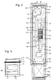
- Fig. 2 shows a section through the ventilation unit along section line II according to Fig. 1 ,
- an air duct 84 which extends in the longitudinal direction of the housing as far as a mixing chamber 86, in which the air conveyed through the air duct 84 can mix with the supply air according to arrow 16.
- a functional unit is thus created, which is basically designed exclusively as a circulating air unit.
- circulating air 48 and / or additional supply air 52 can be sucked in by means of the further fan 46 and conveyed through the channel 84 into the mixing chamber 86 or to the convector 62.
- the functional unit is thus designed as a recirculation unit with additional Frischluftansaugung.
- the convector 62 forms a heating or cooling body, which is designed here as a four-conductor system with four terminals 88. Movable and / or flexible lines according to the dashed line 90 for the heating or cooling medium are connected to these connections 88.
- the further fan 46 is followed by a further closure element 92, which is in particular designed as a pivotable flap.
- the closure element 92 is preferably formed automatically to prevent backflow through the air duct 84 when the blower 46 is switched off.
- a drive unit for the closure member 92 may be provided to control the control unit in accordance with the selected operating mode, to release or shut off the air duct 84.
- the air duct 84 is disposed adjacent to the one longitudinal wall 94, in the insulating material 6, which has a predetermined thickness to the longitudinal wall 94 to achieve the desired insulating effect. Adjacent to the air duct 84 is located in the insulating material 6 of the exhaust duct 26 and adjacent to this in the direction of the other longitudinal wall 96 of the heat exchanger 40 is disposed.
- a bypass channel 98 with a bypass element 100 is arranged in extension of the exhaust air channel 26.
- the bypass element is expediently designed as a pivotable flap and actuated by means of a preferably electric drive unit.
- the drive unit can be regulated or controlled via the control unit. If the connection of the exhaust air channel 26 to the bypass channel 98 is released by means of the bypass element, then the heat exchanger 40 is bypassed and the exhaust air is sucked in directly by the exhaust air blower 36.
- the thus enabled mode, inner heat exchanger bypass is then selected when the fresh air is cooler than the room air, so that with the fresh air, the room 8, for example, to be cooled energetically low for night cooling.
- the ventilation device instead of the previously described arrangement, according to which the blower 36, 18 and 46 are substantially vertically above each other, also be arranged such that the longitudinal axis of the ventilation device is oriented substantially horizontally and said blower side by side lie.
- the ventilation unit is compared with FIGS. 1 and 2 thus arranged rotated by 90 °.
- the housing 2 in the region of the mixing chamber 86 in the longitudinal wall, which according to FIG. 1 in front of or behind the plane of the drawing, the discharge opening 23 'indicated by dashed and dotted lines.
- the convector is arranged below this outflow opening 23 ', wherein the inner lining 10 is designed correspondingly to cover the convector and also the outlet openings for the ascending thermals in free convection in the second position of the convector.
- the convector 62 may be arranged to be translationally movable, as is shown in FIG FIG. 1 indicated by the arrow 102.
- FIG. 3 is a top view of the ventilation unit in the direction of III according to FIG. 2 shown.
- the outer weather protection slats 12, the four-sided clamping frame 4 and the intake opening 32 for the circulating air and the exhaust air are clearly visible.
- the lower mixed air chamber 86 is indicated by dashed lines.
- the inner panel 10 of the housing 2 is formed U-shaped, with a sufficiently large distance between the rear wall 71 and the inner panel 10 to form the above-mentioned channel 72 for the ascending thermal is present.
Landscapes
- Engineering & Computer Science (AREA)
- Chemical & Material Sciences (AREA)
- Combustion & Propulsion (AREA)
- Mechanical Engineering (AREA)
- General Engineering & Computer Science (AREA)
- Air-Flow Control Members (AREA)
- Control Of Motors That Do Not Use Commutators (AREA)
- Input Circuits Of Receivers And Coupling Of Receivers And Audio Equipment (AREA)
- Compressor (AREA)
- Other Air-Conditioning Systems (AREA)
- Ventilation (AREA)
Description
- Die Erfindung bezieht sich auf ein Lüftungsgerät gemäß der im Oberbegriff des Patentanspruchs 1 angegebenen Merkmale.
- Aus der
DE 195 39 811 C2 ist ein derartiges Lüftungsgerät bekannt, welches in einem Gehäuse zumindest ein Zuluft-Gebläse, einen Konvektor und voneinander getrennte Kanäle zur Luftführung enthält, wobei das Gehäuse eine raumaußenseitig liegende Einströmöffnung für die Zuluft und einem Innenraum eines Gebäudes zugeordnete Ausströmöffnung aufweist. Das Lüftungsgerät kann in eine Fassade- oder Fensterkonstruktion eingebaut werden. Ferner enthält das Lüftungsgerät ein Abluft-Gebläse sowie einen Kanal für die Abluft, welche durch eine dem genannten Innenraum zugewandte Ansaugöffnung des Gehäuses angesaugt werden und durch eine Abluftöffnung des Gehäuses nach außen abströmen kann. Zwecks integrierter Energierückgewinnung enthält das Gerät einen Wärmetauscher, um in der Abluft enthaltene Wärme der Zuluft zuzuführen. Der Konvektor ist von einem insbesondere flüssigen Medium durchströmbar und wahlweise als Heizelement oder Kühlelement entsprechend der mit dem Medium zugeführten Energie bzw. Wärme und der vorgegebenen Betriebsart. Soll mittels des Konvektors der genannte Innenraum des Gebäudes bei entsprechender Energie-Wärmezufuhr erwärmt werden, so muss insbesondere das Zuluft-Gebläse in Betrieb sein, um die Zuluft bzw. bei entsprechender Stellung von die Luftströmung beeinflussenden Klappen im Umluftbetrieb den Luftstrom über bzw. durch den Konvektor zu leiten. - Hiervon ausgehend liegt der Erfindung die Aufgabe zugrunde, das Lüftungsgerät der genannten Art mit einem geringen konstruktiven Aufwand dahingehend weiterzubilden, dass der Konvektor gemäß vorwählbarer Betriebsarten effektiv nutzbar ist. Das Lüftungsgerät soll bei kompakter Bauweise funktionssicher für die jeweils gewünschte Betriebsart nutzbar sein. Ferner soll das Lüftungsgerät in einfacher Weise und mit geringem Aufwand für unterschiedliche Einbausituationen zum Einsatz gelangen können.
- Die Lösung dieser Aufgabe erfolgt gemäß der im Patentanspruch 1 angegebenen Merkmale.
- Das vorgeschlagene Lüftungsgerät zeichnet sich durch eine kompakte und funktionsgerechte Konstruktion aus und ermöglicht aufgrund der bewegbaren Anordnung des Konvektors in einer ersten Position einer zwangsweise Luftführung über dem Konvektor, insbesondere bei eingeschaltetem Gebläse, und in einer zweiten Position des Konvektors eine freie Konvektion, und zwar bevorzugt bei abgeschaltetem Gebläse. Der Konvektor ist über geeignete Anschlüsse mit flexibel oder bewegbar ausgebildeten Leitungen verbunden, durch welche ein Medium, wie beispielsweise Wasser, zuführbar ist, um je nach Bedarf Heiz- oder Kühlenergie zuzuführen. Der dem Innenraum eines Gebäudes zugeordnete bzw. raumseitig angeordnete bewegbare Konvektor ist mit dem Gerätegehäuse derart verbunden und/oder diesem zugeordnet, dass im Betrieb keine Luftleckagen entstehen. In zweckmäßiger Weise ist dem Konvektor eine Kondensatschale nachgestellt, um gegebenenfalls die dem Raum zuzuführende Luft gezielt zu entfeuchten und anfallendes Kondensat kontrolliert abzuführen. Um Strömungsgeräusche im Konvektor zu reduzieren, ist der Konvektor in vorteilhafter Weise in einer Wärme- und / oder Schalldämmpackung montiert bzw. angeordnet. Bevorzugt ist der Konvektor auf einer Grundplatte unterhalb des Lüftungsgerätes angeordnet. Insbesondere auf der Grundplatte sind Mittel zur bewegbaren Lagerung des Konvektors vorgesehen, welche Mittel bevorzugt als Drehgelenk, Führungsschienen oder dergleichen ausgebildet sind. Diese Mittel ermöglichen eine Bewegung des Konvektors bei abgeschaltetem Gebläse in Richtung in den Raum hinein, um somit eine freie Konvektion zu ermöglichen. So wird eine gewisse und/oder vorgegebene Grundlast für den zu beheizenden oder zu kühlenden Raum des Gebäudes abgedeckt. Es wird somit dem Raum ohne mechanische Lüftung Energie, Wärme oder Kälte, zugeführt. Diese Betriebsart ist immer dann vorteilhaft, wenn keine Frischluftrate gefordert ist. Die für die Bewegung, insbesondere das Ausklappen und das Einklappen des Konvektors vorgesehene Antriebseinheit, welche bevorzugt als Stellantrieb ausgebildet ist, ist vorteilhaft seitlich am Konvektorrahmen und/oder einer Grundplatte angeordnet.
- Weiterhin ist in Strömungsrichtung nach dem Konvektor ein Temperaturfühler zur Messung der Temperatur der ausströmenden Luft vorgesehen, um eine der Temperatur entsprechende Messgröße einer Regel- und Steuereinheit zuzuführen. Somit wird entsprechend den möglichen variablen Vorgaben insbesondere auf die Ausström- oder Ausblastemperatur Einfluss genommen. Über eine Regel- und Steuereinheit können sämtliche im Lüftungsgerät montierten Komponenten, wie Gebläse, Verschlusselemente oder Klappen der Kanäle, die Antriebseinheit des Konvektors und dergleichen geregelt, gesteuert und überwacht werden. Dies ist insbesondere dann von großem Nutzen, wenn in einem Gebäude eine Vielzahl von dezentralen Lüftungsgeräten montiert ist und diese zur Funktionsprüfung nicht geöffnet werden sollen. Mittels der Regel- und Steuereinheit kann in bevorzugter Weise, beispielsweise via Internet oder Datenleitung, auch eine Fernüberwachung des oder der dezentralen Lüftungsgeräte bzw. Lüftungskomponenten erfolgen.
- Für die Bewegung des Konvektors ist eine Antriebseinheit vorgesehen, mittels welcher der Konvektor in die gewünschte Position bewegbar ist. Der Konvektor ist in vorteilhafter Weise im Bereich der Ausströmöffnung, insbesondere unterhalb derselben, angeordnet. Weiterhin kann der Konvektor im Rahmen der Erfindung in das Gehäuse unmittelbar integriert sein. Die schwenkbare Lagerung des Konvektors, insbesondere an dessen Unterseite, hat sich als besonders zweckmäßig erwiesen, so dass der Konvektor je nach der eingenommenen Betriebsstellung mit der Rückwand des Gehäuses flächenbündig ist oder bei freier Konvektion geöffnet ist. In der Stellung für freie Konvektion ist das Lüftungsgerät an der Unterseite, insbesondere im Bereich der Ausströmöffnung, bevorzugt automatisch verschlossen, so dass im Lüftungsgerät sich eine stehende Luftsäule einstellt, wodurch ein größtmöglicher Wärme- und Schallschutz über das erfindungsgemäße Lüftungsgerät bewirkt ist. Wie bereits ausgeführt, ist der Konvektor wahlweise für Heizung oder Kühlung ausgelegt, zweckmäßig in einem Ein-, Zwei-, Drei- oder Vierleitersystem.
- Gemäß der Erfindung ist ein dezentrales aktives und autarkes sog- und druckgeregeltes Lüftungsgerät mit Heiz- und Kühlmöglichkeit geschaffen. Das Lüftungsgerät ist für den Einbau in eine Fassade- oder Fensterkonstruktion als Boden-, Brüstungs-, Decken- oder Paneelgerät ausgebildet. Das Lüftungsgerät enthält eine Zu-, Ab- und Umlufteinheit, zweckmäßig mit zusätzlich mögliche Frischluftansaugung, und zwar mittels Gebläse unterstützt. Es ist eine integrierte Energierückgewinnung mit einem Wärmetauscher, insbesondere einem Kreuzgegenstrom-Wärmetauscher vorgesehen. In besonders zweckmäßiger Weise ist die Energierückgewinnung mit einer Feuchterückführung ausgebildet, wobei Feuchtigkeit der Abluft der Frischluft zugeführt wird. Sämtliche Luftwege bzw. Kanäle sind konsequent voneinander getrennt, und eine Luftvermischung im Gerät findet nicht statt. Die Kanäle sind als Wärme- und / oder Schalldämmkanäle ausgebildet, und das Gehäuse ist thermisch getrennt. Der Einbau kann nach außen hin sichtbar oder verdeckt liegend erfolgen. Der Luftaustritt bzw. der raumseitige Lufteintritt ist in vorteilhafter Weise möglichst tief zur Erzeugung einer Quelllüftung vorgesehen. Des Weiteren kann je nach Bauvorschrift, Einbauart oder sonstigen Anforderungen raumseitig ein tangentieller Luftaustritt vorgesehen sein. Die Abluft wird entsprechend den zu beachtenden Randbedingungen, Einbausituationen oder dergleichen des Lüftungsgerätes von oben, von vorne oder seitlich zugeführt. Der für Heizung und/oder Kühlung vorgesehene Konvektor ist vorteilhaft im Ein-, Zwei-, Drei- oder Vier-Leitersystem ausgebildet, wobei je nach Bedarf eine Ausführung mit oder ohne Kondensatschale vorgesehen werden kann. Ferner besteht mittels entsprechend angeordneter und ausgebildeter Filter im Lüftungsgerät die Filtermöglichkeit ab EU 2 bis hin zu Pollenfiltern.
- In einer besonderen Ausgestaltung enthält das Lüftungsgerät eine integrierte Regelung des Gebläses, insbesondere dessen Drehzahl, um in Abhängigkeit eines Windsoges und / oder Winddrucks beispielsweise auf die Außenfassade, das Gebläse davon unabhängig zu führen, um somit konstante Volumenströme zu transportieren und konstante Heiz- und / oder Kühlleistungen einzustellen. Hierzu ist vorteilhaft eine Differenzdruckmessung vor und/oder nach wenigstens einem Gebläse, zweckmäßig sämtlichen Gebläsen des Lüftungsgerätes vorgesehen. Somit wird insbesondere über eine Logikeinheit, welche bevorzugt in die Steuer- und Regeleinheit integriert ist, ein zumindest näherungsweise konstanter Volumenstrom innerhalb eines vorgebbaren Druckfensters selbsttätig eingeregelt. Weiterhin sind in zweckmäßiger Weise das Zuluft- und das Abluftgebläse derart insbesondere über die Logikeinheit bzw. die Steuer- und Regeleinheit derart miteinander gekoppelt, dass sich ferner unter den beiden Gebläsen zumindest näherungsweise gleiche Volumenströme einstellen. Denn das eine wird bei Sog einen höheren Volumenstrom fördern als das andere, und bei Druck umgekehrt.
- Das dezentrale Lüftungsgerät, welches in einer Fenster- oder Fassadenkonstruktion angeordnet ist, enthält ein thermisch getrenntes Gehäuse. Aus akustischen und/oder thermischen Gründen sind die Luftwege bzw. Strömungskanäle und ferner im wesentlichen der gesamte Innenraum des Gehäuses mit einem besonderen Dämmaterial ausgekleidet. Des Weiteren sind die Luftwege bzw. Strömungskanäle mit einer speziellen, akustisch transparenten Oberfläche versehen.
- Die Zuluft oder Frischluft wird, bezogen auf den genannten Raum bzw. das Gebäude von außen her angesaugt und über schallgedämmte Kanäle, welche entsprechend der Luftmenge ausgelegt sind, dem Raum wärme- und schallgedämmt zugeführt. Weiterhin wird mittels des Gerätes raumseitig an der Geräteoberseite oder Vorderseite Abluft angesaugt und über die wärme- und schallgedämmten Luftkanäle nach außen hin abgeführt. Mittels eines Wärmetauschers, welcher insbesondere als Kreuzstromplatten-Wärmetauscher ausgebildet ist, wird die in der Abluft enthaltene Energie indirekt der Frischluft zur Energierückgewinnung zugeführt. Somit kann im Sommer kühlere Abluft aus dem Raum wärmere von außen zugeführte Zuluft energetisch günstig kühlen und im Winter energetisch günstig die Zuluft bzw. Frischluft erwärmen.
- In einer besonderen Weiterbildung des Lüftungsgerätes wird mittels einer Bypass-Regelung ein für das Gebäude energetisch günstiger Betrieb ermöglicht, um in denjenigen Betriebsfällen, in welchen keine Energierückgewinnung gewünscht wird, diese bzw. den Wärmetauscher zu umgehen. Diese Betriebsart, welche als innere Wärmetauscher-Umgehung bezeichnet wird, wird dann vorgegeben, wenn die Frischluft kühler als die Raumluft ist und wenn mit der Frischluft der Raum energetisch günstig gekühlt werden soll, insbesondere zwecks Nachtauskühlung oder in Übergangszeiten.
- Weiterhin zeichnet sich das Lüftungsgerät dadurch aus, dass für das bei dem inneren Wärmetauscher anfallende Kondensat eine indirekte feuchte Rückführung vorgesehen ist und somit eine Ableitung des Kondensats durch eine sogenannte Kondensatleitung nicht erforderlich ist. Hierzu ist der Kreuzplatten-Wärmetauscher mit seinen im wesentlichen senkrecht angeordneten Platten jeweils in den Schächten für die Abluft nach unten hin offen ausgebildet, so dass das anfallende Kondensat in eine darunter angeordnete Kondensatschale gelangen bzw. tropfen kann. Diese innere Kondensatschale enthält in vorteilhafter Weise ein Element zur luftdichten Leitung des aufgefangenen Kondensats in den Bereich des Zuluft-Kanals, insbesondere ein für diesen Anwendungsfall bestimmtes Vlies. Eine Luftvermischung zwischen Zuluft und Abluft kann aufgrund der Trennung mittels des Vlieses, bevorzugt in Kombination mit aufgebrachten Stegen, nicht erfolgen. Das anfallende Kondensat wird der trockeneren Zuluft somit indirekt zugeführt, so dass die Zuluft das derart aufgenommene Kondensat dem Raum zuführt.
- Weiterhin werden die getrennten Zuluft- und Abluftwege mittels einer geeigneten Vorrichtung bei abgeschalteten Gebläsen, bevorzugt über die Regel- und/oder Steuereinheit verschlossen, so dass keine unerwünschte Be-, Ent- oder Rückbelüftung über das Lüftungsgerät stattfinden kann.
- In einer besonderen Weiterbildung enthält das Lüftungsgerät eine Funktionseinheit, welche nur als Umlufteinheit oder auch als Umlufteinheit mit zusätzlicher Frischluftansaugung ausgebildet ist und mittels welcher ein erhöhter Heiz- oder Kühlleistungsbedarf bis zu einem möglichen Maximum sicher gestellt wird. Hierbei wird über einen im Lüftungsgerät integrierten, wie vorstehend beschrieben, wärme- und schallgedämmten Luftkanal zusätzlich Raumluft abgesaugt und einer Mischluftkammer vor dem raumseitigen Konvektor zugeführt. Diese integrierte Umlufteinheit zeichnet sich zusätzlich dadurch aus, dass eine selbsttätige Klappe oder dergleichen vorgesehen ist, welche das Rückströmen bei abgeschaltetem Umluftgebläse über dessen Luftkanal verhindert, welcher in die genannte Mischluftkammer mündet. Bei der Ausführungsform mit zusätzlicher Frischluftansaugung über die Umlufteinheit kann über das Öffnen einer stetig geregelten Klappe oder dergleichen Frischluft angesaugt werden. Aufgrund der stetig geregelten Umluft-Frischluftklappe oder dergleichen kann somit die Frischluftrate wesentlich bis zu einem maximal gewünschten bzw. vorgegebenen Wert entsprechend der maximalen Luftleistung der Umlufteinheit erhöht werden.
- Weiterbildungen und besondere Ausgestaltungen der Erfindung sind in den Unteransprüchen sowie der nachfolgenden Beschreibung eines besonderen Ausführungsbeispiels angegeben.
- Die Erfindung wird nachfolgend an Hand des in der Zeichnung dargestellten Ausführungsbeispiels näher erläutert, ohne dass insoweit eine Beschränkung erfolgt. Es zeigen:
- Fig. 1
- einen Schnitt durch Lüftungsgerät in einer vertikalen Ebene,
- Fig. 2
- einen Schnitt entlang Schnittlinie II gemäß
Fig. 1 , - Fig. 3
- eine Aufsicht auf das Lüftungsgerät in Richtung III gemäß
Fig. 2 . - Gemäß
Figur 1 enthält das Lüftungsgerät ein thermisch getrenntes Gehäuse 2 mit einem Einspannrahmen 4, welcher bevorzugt umlaufend und / oder vierseitig ausgebildet ist zwecks Verbindung mit einer Fassade- oder Fensterkonstruktion oder dergleichen. Das Lüftungsgerät kann als Boden-Brüstungs-Decken- oder Paneelgerät zum Einsatz gelangen. Abgesehen von den noch zu erläuternden Luftkanälen, Gebläsen und sonstigen Einbaukomponenten ist das Gehäuse innen im wesentlichen vollständig mit Dämm-Material 6 zur Wärme- und / oder Schalldämmung versehen. Das eingebaute Lüftungsgerät befindet sich zwischen einem Außenraum 7 und einem Raum 8 eines Gebäudes. Dem Raum 8 zugewandt enthält das Lüftungsgerät eine innere Verkleidung 10 und dem Außenraum 7 zugewandt an der Außenseite äußere Wetterschutz-Lamellen 12 oder dergleichen. Das Gehäuse 2 enthält an der Außenseite eine Einströmöffnung 14 für Frischluft oder Zuluft, welche gemäß der Pfeile 16 von einem Zuluft-Gebläse 18 durch einen Zuluftkanal 20, 22 angesaugt und zu einer rauminnenseitigen Ausströmöffnung 23 gefördert wird. Vor dem Zuluftgebläse 18 ist im Zuluftkanal 20 ein Zuluftfilter 24 angeordnet, welcher eine Luftfilterung, bevorzugt ab EU 2 bis hin zu Pollenfilter, ermöglicht. - Ferner ist im Gehäuse 2 bzw. dessen Dämm-Material 6 ein Abluftkanal 26, 28 für aus dem Raum 8 abzuführende Abluft gemäß der Pfeile 30 vorgesehen. Die Abluft 30 wird durch eine gemäß Zeichnung obere Öffnung 32 des Gehäuses 2 sowie einen der Öffnung 32 zugeordneten Filter 34 mittels eines im Inneren des Gehäuses angeordneten Abluftgebläses 36 angesaugt, um über den gemäß Zeichnung nach unten anschließenden Kanal 28 durch eine Ausströmöffnung 38 nach außen zu gelangen.
- Bezogen auf die Längserstreckung des Gehäuses 2 parallel zu dessen Außenwand 39, ist zumindest näherungsweise in der Mitte des Gehäuses 2 ein Wärmetauscher 40 vorgesehen, welcher den bevorzugter Weise als Kreuzstrom-Plattenwärmetauscher ausgebildet ist und eine Energierückgewinnung aus der Abluft für die Zuluft ermöglicht. Zur sicheren konsequenten Trennung des Zuluftkanals 20 vom Abluftkanal 26 befindet sich zwischen diesen Kanälen eine Zwischenwand 42, 43, welche mit dem Wärmetauscher 40 dicht verbunden ist. Unterhalb des Wärmetauschers 40 ist eine Auffangschale 44 für anfallendes Kondensat angeordnet. In der Auffangschale 44 befindet sich ein insbesondere als Vlies ausgebildetes Element 45 zur luftdichten Leitung des aus der Abluft aufgefangenen Kondensats in den Bereich des Zuluft-Kanals 20. Mittels der bis zur Auffangschale 44 bzw. zum Element oder Vlies 45 nach unten geführten Zwischenwand 42 und 43, bevorzugt in Kombination mit aufgebrachten Stegen, erfolgt zuverlässig eine Trennung der Abluft von der Zuluft. Der Wärmetauscher 40 ist mit seinen im wesentlichen senkrecht angeordneten Platten derart ausgebildet, dass dessen Schächte für die Abluft nach unten hin offen sind und somit anfallendes Kondensat in die unterhalb angeordnete Auffangschale 44 gelangen bzw. tropfen kann. Durch das genannte Element bzw. Vlies 45 gelangt das Kondensat in den Bereich des Zuluftkanals 20 hinter der Einströmöffnung 14.
- Das Gehäuse 2 enthält im Bereich der Öffnung 32 ein weiteres Gebläse 46, mittels welchem Umluft gemäß Pfeil 48 durch die Öffnung 32 angesaugt werden kann. Das weitere Gebläse 46 ist hinter einer weiteren Öffnung 50 in dem Gehäuse 2 bzw. dessen Außenwand 39 angeordnet, wobei durch die weitere Öffnung 50 zusätzliche Umluft gemäß Pfeil 52 angesaugt werden kann. Mittels eines Verschlusselements 54, welches insbesondere als eine schwenkbare Klappe ausgebildet ist, kann gemäß der wählbaren Betriebsart die weitere Öffnung 50 verschlossen oder freigegeben werden. Zur Betätigung des Verschlusselements 54 ist ein hier nicht dargestellter, bevorzugt elektrischer Antrieb vorgesehen, welcher von der erwähnten Regel- und Steuereinheit ansteuerbar ist. Auch der etwa in der Mitte der Längserstreckung des Gehäuses 2 angeordneten Einströmöffnung 14 für Zuluft ist ein Verschlusselement 56 zugeordnet, welches gleichfalls als schwenkbar und mittels eines Antriebs betätigbare Klappe ausgebildet ist. Des Weiteren ist der Ausströmöffnung 38 für Abluft ein wiederum bevorzugt als Klappe ausgebildetes Verschlusselement 58 zugeordnet, welches über einen Antrieb betätigbar und entsprechend der gewählten Betriebsart über die Steuer- und Regeleinheit ansteuerbar ist.
- In einer besonderen Ausgestaltung des Lüftungsgerätes ist wenigstens ein Gebläse in Abhängigkeit des Windsogs und des Winddrucks geregelt. Die erfindungsgemäße vom Sog und Winddruck abhängige Regelung wird nachfolgend im Zusammenhang mit dem Zuluft-Gebläse 18 erläutert und ist analog auch bei den anderen Gebläsen 36 und 46 vorgesehen. In Strömungsrichtung der Luft vor dem Zuluft-Gebläse 18 ist ein erster Sensor 60 und nach dem Zuluft-Gebläse 18 ist ein zweiter Sensor 61 im Zuluftkanal 22, 22 angeordnet. Mittels der Sensoren 60, 61 erfolgt eine Differenzdruckmessung und ein entsprechendes Signal wird insbesondere einem Logikelement der Regel- und Steuereinheit zugeführt zur Drehzahlregelung des Zuluft-Gebläses 18. Somit wird ein zumindest näherungsweise konstanter Volumenstrom, bevorzugt innerhalb eines vorgebbaren Druckfensters oder Druckbereiches, selbsttätig eingeregelt. Aufgrund dieser integrierten Regelung wird das Zuluft-Gebläse 18 unabhängig vom Windsog und/oder Winddruck, welcher im Außenraum 7 bzw. an der Fassade vorherrscht, geführt, und es wird aufgrund des im wesentlichen konstanten Volumenstroms eine konstante Heiz- und/oder Kühlleistung gewährleistet. Alternativ oder zusätzlich zum zweiten Sensor 61 im Zuluftkanal 22 kann in bevorzugter Weise im Bereich einer insbesondere unterhalb des Konvektors 62 vorhandenen Auslassöffnung 64 ein weiterer Sensor 61 angeordnet sein zur Drehzahlregelung, insbesondere des Zuluft-Gebläses 18.
- Im Bereich der Ausströmöffnung 23 und zweckmäßig unterhalb derselben ist ein Konvektor 62 bewegbar angeordnet. Zur Befestigung und/oder Verbindung des Konvektors 62 mit dem Gehäuse 2 ist eine Grundplatte 63 vorgesehen, wobei unterhalb des Konvektors 62 die Auslassöffnung 64 vorhanden ist. Zwecks Schall- und/oder Wärmedämmung ist der Konvektor 62 zumindest teilweise innerhalb einer hier nicht dargestellten Packung aus geeignetem Dämmaterial angeordnet. In der dargestellten ersten Position des Konvektors durchströmt die vom Zuluft-Gebläse 18 geförderte Zuluft von oben nach unten durch den Konvektor 62 und gelangt durch die Auslassöffnung 64 in den Raum 8. Mittels Linien 66 ist eine zweite Position des Konvektors angedeutet, welcher hierbei zumindest teilweise in Richtung zum Raum 8 bewegt, und zwar um eine Drehachse 68 geschwenkt ist. Der Konvektor 62 ist auf der Grundplatte 63 mittels eines Lagers um die Drehachse 68 schwenkbar gelagert. In der zweiten Position, in welcher die Ausströmöffnung 23 bevorzugt selbsttätig und/oder mittels eines Absperrorganes 69 geschlossen ist, kann in Folge freier Konvektion der Konvektor von durch die Öffnung 64 einströmende Luft des Raumes 8 von unten nach oben durchströmt werden, um gemäß der Pfeile 70 wieder in den Raum 8 gelangen. In vorteilhafter Weise ist das Absperrorgan mit dem Konvektor 62 derart gekoppelt, dass beim Bewegen und/oder Schwenken des Konvektors 62 in die zweite Position der Strömungsweg vom Zuluftkanal 62 nach außen bzw. durch den Konvektor 62 abgesperrt ist. Befindet sich der Konvektor 62 in der ersten Position, so gibt das Absperrorgan 69 den Strömungsweg vom Zuluftkanal 22 zum und durch den Konvektor 62 frei.
- Der Konvektor 62 ist in vorteilhafter Weise im Bereich der Ausströmöffnung 23 des Zuluftkanals 22 angeordnet, und zwar bevorzugt unterhalb des Gehäuses 2. In einer alternativen Ausgestaltung ist der Konvektor 22 zumindest teilweise innerhalb des Gehäuses 2 angeordnet, und zwar gleichfalls im Bereich der Ausströmöffnung 23. Bei zumindest teilweiser oder kompletter Anordnung des Konvektors 22 im Gehäuse 2 enthält dieses im Bereich des Konvektors 62 wenigstens eine Öffnung und/oder ein Absperrorgan derart, dass in der ersten Position die vom Zuluft-Gebläse 18 geforderte Luft durch den Konvektor 62 gefördert wird, während in der zweiten Position die Raumluft infolge einer Konvektion den Konvektor 62 durchströmt und durch die genannte Öffnung des Gehäuses in den Raum strömen kann. Des Weiteren kann in einer bevorzugten alternativen Ausgestaltung der Erfindung der Konvektor zumindest teilweise im Gehäuse 2 fest angeordnet sein, wobei mittels des genannten Absperrorgans in der ersten Stellung desselben der Strömungsweg der aus dem Gehäuse ausströmenden Luft durch den Konvektor 62 freigegeben ist, während in der zweiten Position die Raumluft den Konvektor 62 in der entgegengesetzten Richtung infolge der Konvektion durchströmt und durch die genannte wenigstens eine Öffnung, welche hierbei freigegeben ist, ausströmt.
- Der Konvektor 62 ist ein Heiz- oder Kühlkörper mit einem Ein-, Zwei-, Drei- oder Vierleitersystem, wobei entsprechend der mittels der Regel- und Steuereinheit vorgegebenen Betriebsart über das zugeführte Medium Wärme oder Kälte zugeführt wird. Die innere Verkleidung 10 ist in einem vorgegebenen Abstand zur Rückwand 71 des Gehäuses 2 angeordnet, so dass ein Kanal 72 vorhanden ist, durch welchen in der zweiten Position die in Folge Konvektion aufsteigende Luft nach oben abströmen und durch entsprechend ausgebildete Öffnungen der inneren Verkleidung 10 in den Raum 8 abströmen kann. Wie ersichtlich, überdeckt die innere Verkleidung 10 auch den Konvektor 62. Der Abstand der inneren Verkleidung 10 zum Gehäuse 2 bzw. zum Konvektor 62 ist derart vorgegeben, dass in der zweiten Position desselben gemäß der Linie 66 die ausströmende Luft oder aufsteigende Thermik gemäß der Pfeile 70 im wesentlichen ungehindert aus dem Konvektor 2 austritt und in den Kanal 72 gelangt. Um den Konvektor 62 in die erste oder zweite Position zu bewegen bzw. zu schwenken, ist eine an der Grundplatte und/oder an der Unterseite des Gehäuses befestigte Antriebseinheit 74 vorgesehen, welche entsprechend der gewünschten Betriebsart mittels der Regel- und Steuereinheit angesteuert wird.
- Unterhalb des Konvektors 62 ist unter Belassung eines freien Durchtritts für die Luft eine Auffangwanne 76 für Kondensat angeordnet bzw. an der Grundplatte 63 befestigt. Die Auffangwanne 76 enthält einen seitlichen Ablaufstutzen 78 für das Kondensat. Zwischen dem Konvektor 72 und diesen übergreifenden inneren Verkleidung 10 ist im Bereich der Auslassöffnung 64 oberhalb derselben ein Strömungskeil 80 angeordnet und entsprechend weiter oben ein Strömungskeil 82, um die aufsteigende Thermik in den Raum 8 zu lenken. Mittels eines dem Konvektor 62 nachgeschalteten Temperaturfühlers 83 wird die Temperatur der ausströmenden Luft erfasst und als Messgröße der Regel- und Steuereinheit zugeführt, um unter Berücksichtigung variabler Vorgaben die Lufttemperatur zu beeinflussen.
-
Fig. 2 zeigt einen Schnitt durch das Lüftungsgerät entlang Schnittlinie II gemäßFig. 1 . An das Gebläse 46 schließt ein Luftkanal 84 an, welcher sich in Längsrichtung des Gehäuses bis zu einer Mischkammer 86 erstreckt, in welcher die durch den Luftkanal 84 geförderte Luft sich mit der Zuluft gemäß Pfeil 16 vermischen kann. In bevorzugter Weise ist somit eine Funktionseinheit geschaffen, welche grundsätzlich ausschließlich als Umlufteinheit ausgebildet ist. Die Mischkammer 86 mündet in die Ausströmöffnung 23. Wie erläutert, kann mittels des weiteren Gebläses 46 Umluft 48 und/oder zusätzliche Zuluft 52 angesaugt und durch den Kanal 84 in die Mischkammer 86 bzw. zum Konvektor 62 gefördert werden. Die Funktionseinheit ist damit als Umlufteinheit mit zusätzlicher Frischluftansaugung ausgebildet. Der Konvektor 62 bildet einen Heiz- oder Kühlkörper, welcher hier als ein Vierleitersystem mit vier Anschlüssen 88 ausgebildet ist. An diese Anschlüsse 88 sind bewegbare und/oder flexible Leitungen gemäß der gestrichelten Linie 90 für das Heiz- bzw. Kühlmedium angeschlossen. - Dem weiteren Gebläse 46 ist ein weiteres Verschlusselement 92 nachgeschaltet, welches insbesondere als schwenkbare Klappe ausgebildet ist. Das Verschlusselement 92 ist bevorzugt selbsttätig ausgebildet, um bei abgeschaltetem Gebläse 46 eine Rückströmung durch den Luftkanal 84 zu unterbinden. Gegebenenfalls kann eine Antriebseinheit für das Verschlusselement 92 vorgesehen sein, um über die Regel- und Steuereinheit entsprechend der gewählten Betriebsart den Luftkanal 84 freizugeben oder abzusperren.
- Der Luftkanal 84 ist benachbart zu der einen Längswand 94 angeordnet, und zwar im Dämmaterial 6, welches zur Längswand 94 eine vorgegebene Dicke zur Erzielung der gewünschten Dämmwirkung aufweist. Nahe der anderen Längswand 96 befindet sich gleichfalls im Dämmaterial 6 der zur Mischkammer 86 führende Zuluftkanal 22. Benachbart zum Luftkanal 84 befindet sich im Dämmaterial 6 der Abluftkanal 26 und benachbart zu diesem in Richtung zur anderen Längswand 96 ist der Wärmetauscher 40 angeordnet.
- In einer besonderen Ausgestaltung des erfindungsgemäßen Lüftungsgeräts ist in Verlängerung des Abluftkanals 26 ein Bypasskanal 98 mit einem Bypasselement 100 angeordnet. Das Bypasselement ist zweckmäßig als eine schwenkbare Klappe ausgebildet und mittels einer bevorzugt elektrischen Antriebseinheit betätigbar. Die Antriebseinheit ist über die Regel- und Steuereinheit regel- bzw. ansteuerbar. Ist mittels des Bypasselements die Verbindung des Abluftkanals 26 zum Bypasskanal 98 freigegeben, so wird der Wärmetauscher 40 umgangen und die Abluft wird direkt vom Abluftgebläse 36 angesaugt. Die damit ermöglichte Betriebsart, innere Wärmetauscherumgehung, wird dann gewählt, wenn die Frischluft kühler als die Raumluft ist, so dass mit der Frischluft der Raum 8 beispielsweise zur Nachtauskühlung energetisch günstig gekühlt werden soll. Durch die erfindungsgemäße Bypassregelung wird somit ein energetisch günstiger Betrieb ermöglicht.
- In einer alternativen Ausgestaltung kann das Lüftungsgerät, anstelle der bisher beschriebenen Anordnung, gemäß welcher die Gebläse 36, 18 und 46 sich im wesentlichen vertikal übereinander befinden, auch derart angeordnet sein, dass die Längsachse des Lüftungsgerätes im wesentlichen horizontal ausgerichtet ist und die genannten Gebläse nebeneinander liegen. In dieser Einbausituation ist das Lüftungsgerät im Vergleich mit
Figuren 1 und2 somit um 90° gedreht angeordnet. Bei dieser Ausgestaltung enthält das Gehäuse 2 im Bereich der Mischkammer 86 in der Längswand, welche gemäßFigur 1 vor bzw. hinter der Zeichenebene liegt, die mit strichpunktierten Linien angedeutete Ausströmöffnung 23'. Analog zu obigen Ausführungen ist unterhalb dieser Ausströmöffnung 23' der Konvektor angeordnet, wobei die innere Verkleidung 10 entsprechend zur Überdeckung des Konvektors ausgebildet ist und ferner die Austrittsöffnungen für die aufsteigende Thermik bei freier Konvektion in der zweiten Position des Konvektors aufweist. - Schließlich kann im Rahmen der Erfindung anstelle der erläuterten schwenkbaren Anordnung der Konvektor 62 translatorisch bewegbar angeordnet sein, wie es in
Figur 1 mit dem Pfeil 102 angedeutet ist. Anstelle der Drehachse sind bei dieser Ausgestaltung geeignete Führungselemente einerseits dem Konvektor 62 und andererseits dem Gehäuse 2 derart zugeordnet, dass im Vergleich mitFigur 1 der Konvektor 62 aus der dargestellten ersten Position durch eine im wesentlichen parallele Verschiebung in Richtung des Pfeiles 102 insgesamt nach rechts bis zur inneren Verkleidung 10 mittels eines entsprechend ausgebildeten Antriebs verschoben werden kann und umgekehrt. - In
Figur 3 ist eine Aufsicht von oben auf das Lüftungsgerät in Blickrichtung III gemäßFigur 2 dargestellt. Die äußeren Wetterschutzlamellen 12, der vierseitige Einspannrahmen 4 sowie die Ansaugöffnung 32 für die Umluft und die Abluft sind gut zu erkennen. Des Weiteren ist mittels gestrichelter Linien die untere Mischluftkammer 86 angedeutet. Wie ersichtlich, ist die innere Verkleidung 10 des Gehäuses 2 U-förmig ausgebildet, wobei zwischen der Rückwand 71 und der inneren Verkleidung 10 ein hinreichend großer Abstand zur Bildung des oben erläuterten Kanals 72 für die aufsteigende Thermik vorhanden ist. -
- 2
- Gehäuse
- 4
- Einspannrahmen
- 6
- Dämm-Material
- 7
- Außenraum
- 8
- Raum eines Gebäudes
- 10
- innere Verkleidung
- 12
- äußere Wetterschutzlamelle
- 14
- Einströmöffnung für Zuluft
- 16
- Pfeil / Zuluft
- 18
- Zuluft-Gebläse
- 20, 22
- Zuluft-Kanal
- 23
- Ausströmöffnung für Zuluft
- 24
- Zuluft-Filter
- 26, 28
- Abluft-Kanal
- 30
- Pfeil / Abluft
- 32
- obere Öffnung
- 34
- Filter für Abluft und Umluft
- 36
- Abluft-Gebläse
- 38
- Ausströmöffnung für Abluft
- 39
- Außenwand von 2
- 40
- Wärmetauscher
- 42
- Zwischenwand
- 44
- Auffangschale
- 45
- Element / Vlies
- 46
- weiteres Gebläse
- 48
- Pfeil / Umluft
- 50
- weitere Öffnung
- 52
- Pfeil / zusätzliche Umluft
- 54
- Klappe / Verschlusselement für 50
- 56
- Klappe / Verschlusselement für 14
- 58
- Klappe / Verschlusselement für 38
- 60, 61
- Sensor für Windsog oder Winddruck
- 62
- bewegbarer Konvektor
- 63
- Grundplatte
- 64
- Auslassöffnung unterhalb von 62
- 66
- Linie
- 68
- Drehachse
- 69
- Absperrorgan
- 70
- Pfeil für aufsteigende Thermik
- 71
- Rückwand
- 72
- Kanal zwischen 10 und 72
- 74
- Antriebseinheit für 62
- 76
- Auffangwanne
- 78
- Ablaufstutzen
- 80, 82
- Strömungskeil
- 83
- Temperaturfühler
- 84
- Luftkanal
- 86
- Mischluftkanal
- 88
- Anschluss
- 90
- gestrichelte Linie, flexible Leitung
- 92
- Klappe / Verschlußelement für 84
- 94
- eine Längswand
- 96
- andere Längswand
- 98
- Bypasskanal
- 100
- Bypasselement
- 102
- Pfeil für translatorische Bewegung von 62
Claims (10)
- Lüftungsgerät für den Einbau zwischen einem Außenraum (7) und einem Raum (8) eines Gebäudes, enthaltend in einem Gehäuse (2) wenigstens ein Gebläse (18), insbesondere für Zuluft, einen Kanal (20, 22) mit einer Einströmöffnung (14) und einer Ausströmöffnung (23) für die mittels des Gebläses (18) durch den Kanal (20, 22) geförderte Luft, sowie einen insbesondere der Ausströmöffnung (23) zugeordneten Konvektor (62), welcher mit Heiz- oder Kühlenergie beaufschlagbar ist,
dadurch gekennzeichnet, dass der Konvektor (62) in zwei Positionen derart bewegbar angeordnet ist, dass in der ersten Position die zur Ausströmöffnung (23) geförderte Luft durch den Konvektor (62) strömt und in der zweiten Position Raumluft in Folge Konvektion den Konvektor (62) durchströmt. - Lüftungsgerät nach Anspruch 1, dadurch gekennzeichnet, dass in der zweiten Position die Ausströmöffnung (23) abgesperrt ist und/oder das Gebläse (18) abgeschaltet ist.
- Lüftungsgerät nach Anspruch 1 oder 2, dadurch gekennzeichnet, dass der Konvektor (62) unterhalb des Gehäuses (2), insbesondere auf einer mit dem Gehäuse (2) verbundenen Grundplatte (63), angeordnet ist und/oder dass der Konvektor (62), insbesondere auf der Grundplatte (63), um eine Drehachse (8) schwenkbar gelagert ist oder dass der Konvektor (62) mittels Führungselementen translatorisch bewegbar ist.
- Lüftungsgerät nach einem der Ansprüche 1 bis 3, dadurch gekennzeichnet, dass zwischen einer dem Raum (8) zugewandten Verkleidung (10) und einer Rückwand (71) des Gehäuses (2) ein Kanal (72) vorgesehen ist, durch welchen in der zweiten Position des Konvektors (62) aus diesem die Luft nach oben abströmt, wobei die innere Verkleidung (10) Luft-Durchtrittsöffnungen aufweist.
- Lüftungsgerät nach einem der Ansprüche 1 bis 4, dadurch gekennzeichnet, dass der Konvektor (62) im Bereich einer Ausströmöffnung (23) des Zuluftkanals (22) angeordnet ist und/oder dass der Konvektor (62) unterhalb des Gehäuses (2) oder zumindest teilweise innerhalb des Gehäuses (2) angeordnet ist und/oder dass in der zweiten Position mittels eines bewegbaren Absperrorgans (69), insbesondere eines Schiebers oder einer Klappe, der Strömungsweg zwischen dem Zuluftkanal (22) und dem Konvektor (62) absperrbar bzw. abgesperrt ist und/oder dass der Konvektor (62) und/oder das Absperrorgan (69) mittels einer Antriebseinheit (74) derart betätigbar sind, dass in der ersten Position der Strömungsweg vom Zuluftkanal (22) zum Konvektor (62) freigegeben und in der zweiten Position abgesperrt ist.
- Lüftungsgerät nach einem der Ansprüche 1 bis 5, dadurch gekennzeichnet, dass der Konvektor (62) und/oder die dem Konvektor (62) zugeordnete Ausströmöffnung (23) in einem der Rückwand (71) naheliegenden Bereich angeordnet ist, und/oder dass zumindest der obere Bereich des Konvektors (62) in der zweiten Position über die Rückwand (71) vorsteht und/oder dass der Konvektor (62) in beiden Positionen von der inneren Verkleidung (10) überdeckt ist.
- Lüftungsgerät nach einem der Ansprüche 1 bis 6, dadurch gekennzeichnet, dass ein Abluftgebläse (36) und ein Wärmetauscher (40), welcher insbesondere als Kreuzstromplattenwärmetauscher ausgebildet ist, vorgesehen sind und/oder dass der Einströmöffnung (14) des Zuluftkanals (20, 22) und/oder der Ausströmöffnung (38) des Abluftkanals (28) bevorzugt elektrisch betätigbare Verschlusselemente (56, 58) zugeordnet sind, welche insbesondere als Klappen ausgebildet sind.
- Lüftungsgerät nach einem der Ansprüche 1 bis 7, dadurch gekennzeichnet, dass ein weiteres Gebläse (46) vorgesehen ist, mittels welchem bedarfsweise Umluft aus dem Raum (8) und/oder zusätzliche Zuluft von außen ansaugbar und in einen Luftkanal (84) förderbar ist, wobei der Luftkanal (84) bevorzugt in eine Mischkammer (86) mündet, in welche gleichfalls der Zuluftkanal (22) mündet, und wobei die Mischluftkammer (86) vor der Ausströmöffnung (23) oder dem Kollektor (62) angeordnet ist.
- Lüftungsgerät nach einem der Ansprüche 1 bis 8, dadurch gekennzeichnet, dass eine vom Winddruck oder Windsog abhängige Regelung des oder der Gebläse (18, 36, 46) vorgesehen ist, enthaltend wenigstens einen Sensor (60, 61), insbesondere zur Differenzdruckmessung vor und hinter dem Gebläse (18, 36, 46), wobei in Abhängigkeit der Sensorsignale eine Drehzahlregelung des oder der Gebläse (18, 36, 46) für einen im wesentlichen konstanten Volumenstrom erfolgt.
- Lüftungsgerät, insbesondere nach einem der Ansprüche 1 bis 9, dadurch gekennzeichnet, dass eine Bypassregelung zur bedarfsweisen Umgehung des Wärmetauschers (40) vorgesehen ist, wobei zwischen dem zum Wärmetauscher führenden Abluftkanal (26) und dem Abluftgebläse (36) ein Bypasskanal (98) zur Umgehung des Wärmetauschers (40) angeordnet ist und wobei dem Bypasskanal (98) ein Bypasselement (100) zugeordnet ist, welches insbesondere als eine schwenkbare Klappe ausgebildet ist und welches mittels einer bevorzugt elektrischen Antriebseinheit betätigbar ist, um den Bypasskanal (98) entsprechend der gewählten Betriebsart ganz oder teilweise abzusperren bzw. freizugeben.
Applications Claiming Priority (4)
| Application Number | Priority Date | Filing Date | Title |
|---|---|---|---|
| DE10257325 | 2002-12-06 | ||
| DE10257325 | 2002-12-06 | ||
| DE10307047 | 2003-02-20 | ||
| DE2003107047 DE10307047A1 (de) | 2003-02-20 | 2003-02-20 | Lüftungsgerät |
Publications (3)
| Publication Number | Publication Date |
|---|---|
| EP1426706A2 EP1426706A2 (de) | 2004-06-09 |
| EP1426706A3 EP1426706A3 (de) | 2006-05-17 |
| EP1426706B1 true EP1426706B1 (de) | 2008-08-20 |
Family
ID=32313576
Family Applications (1)
| Application Number | Title | Priority Date | Filing Date |
|---|---|---|---|
| EP03025179A Expired - Lifetime EP1426706B1 (de) | 2002-12-06 | 2003-11-04 | Lüftungsgerät |
Country Status (3)
| Country | Link |
|---|---|
| EP (1) | EP1426706B1 (de) |
| AT (1) | ATE405800T1 (de) |
| DE (1) | DE50310350D1 (de) |
Families Citing this family (3)
| Publication number | Priority date | Publication date | Assignee | Title |
|---|---|---|---|---|
| KR100628042B1 (ko) * | 2005-02-15 | 2006-09-26 | 엘지전자 주식회사 | 환기시스템 |
| DE202010004803U1 (de) * | 2010-04-09 | 2011-09-02 | Stiebel Eltron Gmbh & Co. Kg | Lüftungsanlage und Luftfilter |
| BE1031084B1 (nl) * | 2022-11-30 | 2024-06-24 | Vero Duco | Hygienisch balansventilatiesysteem en werkwijze voor het aansturen van een dergelijke ventilatiesysteem |
Family Cites Families (5)
| Publication number | Priority date | Publication date | Assignee | Title |
|---|---|---|---|---|
| DE3632268A1 (de) * | 1986-09-23 | 1988-04-07 | Alois Laternser | Verfahren und vorrichtung zum belueften eines raumes |
| DE19539811C2 (de) | 1995-10-26 | 2000-02-24 | Altura Leiden Holding | Lüftungsvorrichtung |
| DE19810357A1 (de) * | 1998-03-10 | 1999-09-16 | Olsberg Hermann Everken Gmbh | Lüftungs-Heizvorrichtung |
| DE19911645A1 (de) * | 1999-03-16 | 2000-09-21 | Volkswagen Ag | Heizvorrichtung zur Erwärmung eines Luftstroms |
| DE20114892U1 (de) * | 2001-05-11 | 2002-01-17 | FensterSystemLüftung GmbH & Co. KG, 68199 Mannheim | Lüftungssystem zum dezentralen Belüften von Räumen in Gebäuden |
-
2003
- 2003-11-04 EP EP03025179A patent/EP1426706B1/de not_active Expired - Lifetime
- 2003-11-04 AT AT03025179T patent/ATE405800T1/de not_active IP Right Cessation
- 2003-11-04 DE DE50310350T patent/DE50310350D1/de not_active Expired - Lifetime
Also Published As
| Publication number | Publication date |
|---|---|
| DE50310350D1 (de) | 2008-10-02 |
| EP1426706A3 (de) | 2006-05-17 |
| ATE405800T1 (de) | 2008-09-15 |
| EP1426706A2 (de) | 2004-06-09 |
Similar Documents
| Publication | Publication Date | Title |
|---|---|---|
| DE3521959C2 (de) | ||
| WO1982000337A1 (en) | Air regulation installation for a front wall element allowing energy savings | |
| DE69800482T2 (de) | Klimaanlage mit klappe zur umlenkung des luftstromes für kühlung oder heizung | |
| EP2405207B1 (de) | Klimatisierungsvorrichtung zum Einbau in eine Raumdecke | |
| DE102010042948B4 (de) | Dezentrale Raumlüftungsvorrichtung mit Wärmerückgewinnung | |
| DE3405584C2 (de) | ||
| EP3165838A1 (de) | Vorrichtung zum belüften von räumen | |
| EP1426706B1 (de) | Lüftungsgerät | |
| DE19539811C2 (de) | Lüftungsvorrichtung | |
| DE2149906C3 (de) | Kühlvorrichtung für einen Antriebsmotor eines Panzerfahrzeuges | |
| DE102006024658A1 (de) | Einrichtung für Dunstabzugshauben zum Wechselbetrieb zwischen Umluft und abluft, abhängig von der Außentemperatur | |
| DE102005024444A1 (de) | Kühlsystem | |
| DE10307047A1 (de) | Lüftungsgerät | |
| DE102005011222A1 (de) | Lüftungsanlage | |
| DE2536297A1 (de) | Luftaufbereitungsventilator | |
| DE10346732A1 (de) | Verfahren und Anordnung zur Klimatisierung eines Raumes | |
| DE20209031U1 (de) | Belüftungssystem zur Raumbe- und -entlüftung | |
| DE2706593A1 (de) | Vorrichtung zum beheizen, belueften und kuehlen von grossen fahrzeugraeumen | |
| EP3916314B1 (de) | Lüftungssystem | |
| DE19907844C2 (de) | Lüftungsgerät für die Räume von Gebäuden | |
| DE19535290C1 (de) | Klimatisierungseinrichtung zum Einbau in einen Dachkanal eines Nutzfahrzeugs, insbesondere Omnibusses | |
| DE29518108U1 (de) | Gerät zur Belüftung von Räumen | |
| DE202008014287U1 (de) | Hybride Raumlüftungsvorrichtung | |
| DE102010050991A1 (de) | Klimaanlage eines Kraftfahrzeugs | |
| DE102010011918A1 (de) | Verfahren zum Betreiben eines lufttechnischen Geräts, lufttechnisches Gerät und Raum mit lufttechnischem Gerät |
Legal Events
| Date | Code | Title | Description |
|---|---|---|---|
| PUAI | Public reference made under article 153(3) epc to a published international application that has entered the european phase |
Free format text: ORIGINAL CODE: 0009012 |
|
| AK | Designated contracting states |
Kind code of ref document: A2 Designated state(s): AT BE BG CH CY CZ DE DK EE ES FI FR GB GR HU IE IT LI LU MC NL PT RO SE SI SK TR |
|
| AX | Request for extension of the european patent |
Extension state: AL LT LV MK |
|
| RAP1 | Party data changed (applicant data changed or rights of an application transferred) |
Owner name: ERWIN MUELLER GMBH |
|
| PUAL | Search report despatched |
Free format text: ORIGINAL CODE: 0009013 |
|
| AK | Designated contracting states |
Kind code of ref document: A3 Designated state(s): AT BE BG CH CY CZ DE DK EE ES FI FR GB GR HU IE IT LI LU MC NL PT RO SE SI SK TR |
|
| AX | Request for extension of the european patent |
Extension state: AL LT LV MK |
|
| RIC1 | Information provided on ipc code assigned before grant |
Ipc: F24F 12/00 20060101AFI20040316BHEP Ipc: F24F 7/08 20060101ALI20060329BHEP |
|
| 17P | Request for examination filed |
Effective date: 20060718 |
|
| AKX | Designation fees paid |
Designated state(s): AT BE BG CH CY CZ DE DK EE ES FI FR GB GR HU IE IT LI LU MC NL PT RO SE SI SK TR |
|
| GRAP | Despatch of communication of intention to grant a patent |
Free format text: ORIGINAL CODE: EPIDOSNIGR1 |
|
| GRAS | Grant fee paid |
Free format text: ORIGINAL CODE: EPIDOSNIGR3 |
|
| GRAA | (expected) grant |
Free format text: ORIGINAL CODE: 0009210 |
|
| AK | Designated contracting states |
Kind code of ref document: B1 Designated state(s): AT BE BG CH CY CZ DE DK EE ES FI FR GB GR HU IE IT LI LU MC NL PT RO SE SI SK TR |
|
| REG | Reference to a national code |
Ref country code: GB Ref legal event code: FG4D Free format text: NOT ENGLISH |
|
| REG | Reference to a national code |
Ref country code: CH Ref legal event code: NV Representative=s name: SCHNEIDER FELDMANN AG PATENT- UND MARKENANWAELTE Ref country code: CH Ref legal event code: EP |
|
| REG | Reference to a national code |
Ref country code: IE Ref legal event code: FG4D Free format text: LANGUAGE OF EP DOCUMENT: GERMAN |
|
| REF | Corresponds to: |
Ref document number: 50310350 Country of ref document: DE Date of ref document: 20081002 Kind code of ref document: P |
|
| PG25 | Lapsed in a contracting state [announced via postgrant information from national office to epo] |
Ref country code: ES Free format text: LAPSE BECAUSE OF FAILURE TO SUBMIT A TRANSLATION OF THE DESCRIPTION OR TO PAY THE FEE WITHIN THE PRESCRIBED TIME-LIMIT Effective date: 20081201 Ref country code: NL Free format text: LAPSE BECAUSE OF FAILURE TO SUBMIT A TRANSLATION OF THE DESCRIPTION OR TO PAY THE FEE WITHIN THE PRESCRIBED TIME-LIMIT Effective date: 20080820 |
|
| PG25 | Lapsed in a contracting state [announced via postgrant information from national office to epo] |
Ref country code: SI Free format text: LAPSE BECAUSE OF FAILURE TO SUBMIT A TRANSLATION OF THE DESCRIPTION OR TO PAY THE FEE WITHIN THE PRESCRIBED TIME-LIMIT Effective date: 20080820 Ref country code: FI Free format text: LAPSE BECAUSE OF FAILURE TO SUBMIT A TRANSLATION OF THE DESCRIPTION OR TO PAY THE FEE WITHIN THE PRESCRIBED TIME-LIMIT Effective date: 20080820 |
|
| PGFP | Annual fee paid to national office [announced via postgrant information from national office to epo] |
Ref country code: AT Payment date: 20081128 Year of fee payment: 6 |
|
| REG | Reference to a national code |
Ref country code: IE Ref legal event code: FD4D |
|
| PG25 | Lapsed in a contracting state [announced via postgrant information from national office to epo] |
Ref country code: IE Free format text: LAPSE BECAUSE OF FAILURE TO SUBMIT A TRANSLATION OF THE DESCRIPTION OR TO PAY THE FEE WITHIN THE PRESCRIBED TIME-LIMIT Effective date: 20080820 Ref country code: DK Free format text: LAPSE BECAUSE OF FAILURE TO SUBMIT A TRANSLATION OF THE DESCRIPTION OR TO PAY THE FEE WITHIN THE PRESCRIBED TIME-LIMIT Effective date: 20080820 Ref country code: BG Free format text: LAPSE BECAUSE OF FAILURE TO SUBMIT A TRANSLATION OF THE DESCRIPTION OR TO PAY THE FEE WITHIN THE PRESCRIBED TIME-LIMIT Effective date: 20081120 |
|
| PG25 | Lapsed in a contracting state [announced via postgrant information from national office to epo] |
Ref country code: SK Free format text: LAPSE BECAUSE OF FAILURE TO SUBMIT A TRANSLATION OF THE DESCRIPTION OR TO PAY THE FEE WITHIN THE PRESCRIBED TIME-LIMIT Effective date: 20080820 Ref country code: CZ Free format text: LAPSE BECAUSE OF FAILURE TO SUBMIT A TRANSLATION OF THE DESCRIPTION OR TO PAY THE FEE WITHIN THE PRESCRIBED TIME-LIMIT Effective date: 20080820 Ref country code: PT Free format text: LAPSE BECAUSE OF FAILURE TO SUBMIT A TRANSLATION OF THE DESCRIPTION OR TO PAY THE FEE WITHIN THE PRESCRIBED TIME-LIMIT Effective date: 20090120 Ref country code: RO Free format text: LAPSE BECAUSE OF FAILURE TO SUBMIT A TRANSLATION OF THE DESCRIPTION OR TO PAY THE FEE WITHIN THE PRESCRIBED TIME-LIMIT Effective date: 20080820 |
|
| BERE | Be: lapsed |
Owner name: ERWIN MULLER G.M.B.H. Effective date: 20081130 |
|
| PLBE | No opposition filed within time limit |
Free format text: ORIGINAL CODE: 0009261 |
|
| STAA | Information on the status of an ep patent application or granted ep patent |
Free format text: STATUS: NO OPPOSITION FILED WITHIN TIME LIMIT |
|
| PG25 | Lapsed in a contracting state [announced via postgrant information from national office to epo] |
Ref country code: MC Free format text: LAPSE BECAUSE OF NON-PAYMENT OF DUE FEES Effective date: 20081130 |
|
| PGFP | Annual fee paid to national office [announced via postgrant information from national office to epo] |
Ref country code: CH Payment date: 20090225 Year of fee payment: 6 |
|
| 26N | No opposition filed |
Effective date: 20090525 |
|
| GBPC | Gb: european patent ceased through non-payment of renewal fee |
Effective date: 20081120 |
|
| PG25 | Lapsed in a contracting state [announced via postgrant information from national office to epo] |
Ref country code: EE Free format text: LAPSE BECAUSE OF FAILURE TO SUBMIT A TRANSLATION OF THE DESCRIPTION OR TO PAY THE FEE WITHIN THE PRESCRIBED TIME-LIMIT Effective date: 20080820 |
|
| PG25 | Lapsed in a contracting state [announced via postgrant information from national office to epo] |
Ref country code: IT Free format text: LAPSE BECAUSE OF FAILURE TO SUBMIT A TRANSLATION OF THE DESCRIPTION OR TO PAY THE FEE WITHIN THE PRESCRIBED TIME-LIMIT Effective date: 20080820 |
|
| REG | Reference to a national code |
Ref country code: FR Ref legal event code: ST Effective date: 20090731 |
|
| PG25 | Lapsed in a contracting state [announced via postgrant information from national office to epo] |
Ref country code: BE Free format text: LAPSE BECAUSE OF NON-PAYMENT OF DUE FEES Effective date: 20081130 |
|
| PG25 | Lapsed in a contracting state [announced via postgrant information from national office to epo] |
Ref country code: GB Free format text: LAPSE BECAUSE OF NON-PAYMENT OF DUE FEES Effective date: 20081120 |
|
| PG25 | Lapsed in a contracting state [announced via postgrant information from national office to epo] |
Ref country code: SE Free format text: LAPSE BECAUSE OF FAILURE TO SUBMIT A TRANSLATION OF THE DESCRIPTION OR TO PAY THE FEE WITHIN THE PRESCRIBED TIME-LIMIT Effective date: 20081120 |
|
| REG | Reference to a national code |
Ref country code: CH Ref legal event code: PL |
|
| PG25 | Lapsed in a contracting state [announced via postgrant information from national office to epo] |
Ref country code: LU Free format text: LAPSE BECAUSE OF NON-PAYMENT OF DUE FEES Effective date: 20081104 Ref country code: HU Free format text: LAPSE BECAUSE OF FAILURE TO SUBMIT A TRANSLATION OF THE DESCRIPTION OR TO PAY THE FEE WITHIN THE PRESCRIBED TIME-LIMIT Effective date: 20090221 Ref country code: CY Free format text: LAPSE BECAUSE OF FAILURE TO SUBMIT A TRANSLATION OF THE DESCRIPTION OR TO PAY THE FEE WITHIN THE PRESCRIBED TIME-LIMIT Effective date: 20080820 |
|
| PG25 | Lapsed in a contracting state [announced via postgrant information from national office to epo] |
Ref country code: TR Free format text: LAPSE BECAUSE OF FAILURE TO SUBMIT A TRANSLATION OF THE DESCRIPTION OR TO PAY THE FEE WITHIN THE PRESCRIBED TIME-LIMIT Effective date: 20080820 Ref country code: AT Free format text: LAPSE BECAUSE OF NON-PAYMENT OF DUE FEES Effective date: 20091104 |
|
| PG25 | Lapsed in a contracting state [announced via postgrant information from national office to epo] |
Ref country code: LI Free format text: LAPSE BECAUSE OF NON-PAYMENT OF DUE FEES Effective date: 20091130 Ref country code: CH Free format text: LAPSE BECAUSE OF NON-PAYMENT OF DUE FEES Effective date: 20091130 Ref country code: GR Free format text: LAPSE BECAUSE OF FAILURE TO SUBMIT A TRANSLATION OF THE DESCRIPTION OR TO PAY THE FEE WITHIN THE PRESCRIBED TIME-LIMIT Effective date: 20081121 |
|
| PGFP | Annual fee paid to national office [announced via postgrant information from national office to epo] |
Ref country code: DE Payment date: 20101220 Year of fee payment: 8 |
|
| PG25 | Lapsed in a contracting state [announced via postgrant information from national office to epo] |
Ref country code: FR Free format text: LAPSE BECAUSE OF NON-PAYMENT OF DUE FEES Effective date: 20081130 |
|
| REG | Reference to a national code |
Ref country code: DE Ref legal event code: R119 Ref document number: 50310350 Country of ref document: DE Effective date: 20120601 |
|
| PG25 | Lapsed in a contracting state [announced via postgrant information from national office to epo] |
Ref country code: DE Free format text: LAPSE BECAUSE OF NON-PAYMENT OF DUE FEES Effective date: 20120601 |