EP1426734A1 - Dispositif et procédé pour identifier un noeud - Google Patents
Dispositif et procédé pour identifier un noeud Download PDFInfo
- Publication number
- EP1426734A1 EP1426734A1 EP03022023A EP03022023A EP1426734A1 EP 1426734 A1 EP1426734 A1 EP 1426734A1 EP 03022023 A EP03022023 A EP 03022023A EP 03022023 A EP03022023 A EP 03022023A EP 1426734 A1 EP1426734 A1 EP 1426734A1
- Authority
- EP
- European Patent Office
- Prior art keywords
- arrangement
- master unit
- actuators
- node
- measuring device
- Prior art date
- Legal status (The legal status is an assumption and is not a legal conclusion. Google has not performed a legal analysis and makes no representation as to the accuracy of the status listed.)
- Granted
Links
- 238000000034 method Methods 0.000 title claims description 29
- 238000005259 measurement Methods 0.000 claims description 13
- 238000012790 confirmation Methods 0.000 description 1
- 230000001419 dependent effect Effects 0.000 description 1
- 238000004100 electronic packaging Methods 0.000 description 1
- 238000004519 manufacturing process Methods 0.000 description 1
- 230000000737 periodic effect Effects 0.000 description 1
Images


Classifications
-
- G—PHYSICS
- G01—MEASURING; TESTING
- G01D—MEASURING NOT SPECIALLY ADAPTED FOR A SPECIFIC VARIABLE; ARRANGEMENTS FOR MEASURING TWO OR MORE VARIABLES NOT COVERED IN A SINGLE OTHER SUBCLASS; TARIFF METERING APPARATUS; MEASURING OR TESTING NOT OTHERWISE PROVIDED FOR
- G01D21/00—Measuring or testing not otherwise provided for
- G01D21/02—Measuring two or more variables by means not covered by a single other subclass
Definitions
- the present invention relates to an arrangement and a method for identifying a node of a network system for devices with movable parts.
- a second disadvantage of known industrial bus network systems of machine tools is that they often are inflexible in their identification of a node when they use hardware dip switches.
- One aspect of the present invention regards an arrangement including a plurality of movable parts, wherein each movable part is connected to a corresponding actuator and a measuring device that determines a position of one of the actuators.
- a master unit is coupled to the actuators and to the measuring device, wherein the master unit receives measurement signals from the measuring device and sends control signals to the actuators so as to control movement of the plurality of movable parts, wherein the master unit distinguishes a node associated with the one of the actuators upon detecting movement of the movable part via the measurement signals.
- said actuator comprises a motor
- said one of said actuators rotates about an axis.
- said measuring device is a linear or a rotary encoder.
- said master unit comprises a configuration file with node identification, serial numbers, axis label and other product specific information related to said measuring device.
- a user interface is provided that is coupled to said master unit, said user interface enables an operator to manually input set-up information.
- a serial bus structure that connects said master unit, said actuators and said measuring device to one another.
- a second aspect of the present invention regards a method of identifying a node of an arrangement that includes a plurality of movable parts, wherein each movable part is connected to a corresponding actuator.
- the method includes moving only one of a plurality of movable parts of said arrangement.
- the movement is detected by a measuring device that detemines a position of said one of plurality of movable parts and that sends measurement signals to a master unit.
- the master unit is coupled to said actuators for controlling movement of said plurality of movable parts by sending control signals to said actuators.
- a node associated with one of said plurality of movable parts is distinguished based on said detecting movement via said measurement signals.
- said measuring device is programmed with a default node identification prior to said moving.
- said arrangement is checked to insure its integrity prior to said moving.
- said method further comprises stopping said arrangement prior to said moving and placing all nodes of said arrangement into a configurable state after said stopping and prior to said moving.
- said method further comprises naming a desired node identification for a particular axis of movement of said arrangement prior to said moving.
- said method further comprises having said measurement device enter said configurable state.
- only one node of said arrangement may be in said configurable state at any particular time.
- Each aspect of the present invention provides the advantage of improving the adjusting of settings of industrial bus network systems.
- Each aspect of the present invention provides the advantage of improving the flexibility in the identification of a node of industrial bus network systems.
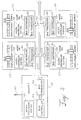
- FIG. 1 schematically shows an arrangement 100 having movable parts 102, 104, 106, 108 and a system for controlling the movement of these movable parts.
- the arrangement includes a plurality of controllable actuators 110, 112, 114 and 116 for causing the movement of the movable parts.
- the actuators may be motors and the movable parts may be rotatable about axes, according to an embodiment of the invention.
- the movable parts 102, 104, 106, 108 co-operate with measuring devices, i.e. devices for generating a signal indicative of a position or movement, such as optoelectrical positioning measuring devices 118 that include an encoding structure that has an optically readable pattern.
- the encoding pattern is read by one or more detectors which each deliver an electric signal in relation to the amount of light that is received in the detector, so that movement of the encoding pattern in relation to the detector will be indicated by changes in the electric signal.
- the encoding pattern includes a periodic pattern, such as a plurality of light and dark fields of mutually the same size, for instance.
- Some position measurement devices provide a position signal comprising a plurality of pulse signals, where the state of the pulse signals at an instant of time defines the absolute position of the encoding disc in relation to the detector. These position measuring devices are also referred to as absolute encoders.
- a master unit 120 is coupled to the measuring devices 118 for receiving the measurement signals.
- the master unit 120 is also coupled to the actuators 110, 112, 114 and 116 via lines 123 for providing control signals so as to control the movement of the movable parts 102, 104, 106 and 108 in dependence on the measurement signals.
- the master unit 120 is coupled to the measuring devices 118 via a serial data bus 122.
- the master unit 120 includes a microprocessor system 125 that receives the position signals from the measuring devices 118 and controls the actuators 110, 112, 114 and 116 and the positions of the associated movable parts.
- the microprocessor system 125 maintains a configuration file with node identification, serial numbers, axis label and other product specific information related to the encoders of the measuring devices 118.
- the signals that are received by and sent by the master unit 120 are controlled by a bus controller 124 and bus transceiver 126 whose structure and function are well known in the art.
- each interface unit is identical in structure and includes a microcontroller system 128 that is used to control its associated actuator.
- Each interface unit also includes a bus controller 130 and a bus transceiver 132 whose structure and function are well known in the art. The signals received and sent by the movable parts are controlled by the bus controller 130 and bus transceiver 132.
- the master unit 120 is coupled to a user interface 134 for enabling an operator to manually input set-up information in accordance with the present invention.
- the user interface 134 includes a display 136 and a data input device 138, such as a mouse or a keyboard.
- the node identification values are implemented via user interface 134 that is coupled to a network, such as a CANOpen network, with linear encoders.
- the network is composed of a number of nodes, wherein a node is a single device that can communicate independently on the network, such as a measuring device, I/O module or a motor.
- a node is a single device that can communicate independently on the network, such as a measuring device, I/O module or a motor.
- the encoders of the measuring devices 118 leave the factory, they will be programmed with a default node identification that is not unique to the particular measuring device.
- the master unit 120 queries the user via user interface 134 whether or not the network is to be reconfigured per step 202. If the network is to be reconfigured, it is reconfigured via user interface 134 per step 206. If the network is not to be reconfigured, the master unit 120 checks to see if the desired configuration is saved for the network per step 204 of FIG. 3. The saved configuration is a list of each encoder's node identification and serial number. If it is determined that there is a saved configuration, the master unit 120 then verifies the saved configuration by querying each saved node identification for its current serial number and comparing the response to the saved serial number for that node identification. This insures the integrity of the network and that a new node with an existing identification is not placed on the network. If the desired configuration is saved and valid, the master unit 120 implements the saved configuration and the configuration process is discontinued per step 226.
- the master unit 120 will need to cause all nodes on the network to enter a non-configurable state per step 206 and configure each node/encoder and assign node identifications. This is accomplished by having the master unit 120 stop the network and place all nodes of the arrangement 100 into a non-configurable state by means such as the CANOpen Layer Setting Service LSS, per step 206. At this stage the master unit 120, prompts the user via the user interface 134 to assign and enter a desired node identification for a particular axis of movement of the arrangement 100 per step 208. Alternately, the user may let the master unit 120 assign node identifications automatically.
- the master unit 120 determines if the entered node identification is valid. If it is not, then the user interface 134 informs the user that the entered node identification is not valid and requests the user to enter a new node identification per step 210.
- the validity of a node identification is determined by being a unique integer value within a predetermined range, for example, a valid CANOpen node identification would be an integer value between 1 and 127, such as 29.
- the master unit 120 At this point of the process where the entered node identification has been validated per step 210, the master unit 120 generates a message at user interface 134 that prompts the user, per step 212, to move the particular axis associated with the node by either a small distance in the case of a node corresponding to a linear encoder or a small angle in the case of a node corresponding to a rotary encoder.
- the user moves the particular axis of a moving part via the user interface 134 per step 214.
- the encoder of the measuring device 118 connected to the particular axis associated with steps 212 and 214 recognizes that it has moved by comparing its present count value with its previous count value and determining that there is a difference between the two count values.
- the measuring device 118 associated with the particular axis changes into a configurable state, such as the LSS Configuration Mode.
- the selected encoder sends a message, such as a CANOpen Transmit Process Data Object (TPDO) message, to the master unit 120 so as to signify that the displaced encoder has changed into a configurable state, such as it has changed to the LSS Configuration Mode, per step 214.
- TPDO CANOpen Transmit Process Data Object
- the master unit 120 determines that the encoder associated with steps 208 and 214 has been placed in a configurable state, such as the LSS Configuration Mode, wherein only one node may be at any particular time.
- the master unit 120 Besides determining that an encoder is in a configurable state, the master unit 120 performs a query of the serial number of the encoder. Upon receipt of the serial number per step 216, the master unit 120 sends a new node identification to the encoder, such as defined in the CANOpen LSS protocol per step 218. Upon receipt of its new node identification, the encoder saves the configuration per step 220 and sends a confirmation message to the master unit 120 indicating that the encoder has received the new node identification.
- the master unit 120 With the new node identification in place for the displaced encoder, the master unit 120 resets the microprocessor 125 and saves the configuration data of the displaced encoder per step 222, such as the new node identification, the axis label associated with the encoder and the serial number of the encoder.
- the above process is able to distinguish one node from other nodes of a network of encoders by displacing an encoder associated with the node to be distinguished
- the master unit 120 determines if there are other axes or nodes that need to the distinguished in the network per step 224. If there are, then the process is repeated beginning at step 206. If there are no further axes or nodes to distinguish, then the process is completed per step 226. Note that if at the time power is turned off the configuration of the master unit 120 or the encoder saved, then the system will revert to the previously saved configuration for the master unit and encoder upon powering up the system.
Landscapes
- Physics & Mathematics (AREA)
- General Physics & Mathematics (AREA)
- Small-Scale Networks (AREA)
- Transmission And Conversion Of Sensor Element Output (AREA)
- Data Exchanges In Wide-Area Networks (AREA)
- Packaging Of Special Articles (AREA)
- Sorting Of Articles (AREA)
- Control Of Position Or Direction (AREA)
Applications Claiming Priority (2)
| Application Number | Priority Date | Filing Date | Title |
|---|---|---|---|
| US10/313,064 US6807512B2 (en) | 2002-12-06 | 2002-12-06 | Node identification by displacement |
| US313064 | 2002-12-06 |
Publications (2)
| Publication Number | Publication Date |
|---|---|
| EP1426734A1 true EP1426734A1 (fr) | 2004-06-09 |
| EP1426734B1 EP1426734B1 (fr) | 2010-09-15 |
Family
ID=32312282
Family Applications (1)
| Application Number | Title | Priority Date | Filing Date |
|---|---|---|---|
| EP03022023A Expired - Lifetime EP1426734B1 (fr) | 2002-12-06 | 2003-10-01 | Dispositif et procédé pour identifier un noeud |
Country Status (5)
| Country | Link |
|---|---|
| US (1) | US6807512B2 (fr) |
| EP (1) | EP1426734B1 (fr) |
| CN (1) | CN1514319B (fr) |
| AT (1) | ATE481621T1 (fr) |
| DE (1) | DE60334184D1 (fr) |
Families Citing this family (2)
| Publication number | Priority date | Publication date | Assignee | Title |
|---|---|---|---|---|
| DE102017117288A1 (de) * | 2017-07-31 | 2019-01-31 | Hengstler Gmbh | Datenübertragungsverfahren zwischen einem Drehwinkelgeber und einer Motorsteuereinrichtung oder einer Auswerteeinheit |
| DE102024131847A1 (de) * | 2024-10-31 | 2026-04-30 | Turck Holding Gmbh | Kommunikationsgerät und Verfahren zum Betreiben eines Kommunikationsgeräts |
Citations (6)
| Publication number | Priority date | Publication date | Assignee | Title |
|---|---|---|---|---|
| US4656463A (en) * | 1983-04-21 | 1987-04-07 | Intelli-Tech Corporation | LIMIS systems, devices and methods |
| US5499374A (en) * | 1992-03-06 | 1996-03-12 | Pitney Bowes Inc. | Event driven communication network |
| EP0866316A1 (fr) * | 1997-03-18 | 1998-09-23 | Endevco Corporation | Système capteur intelligent avec bus de réseau |
| EP0950875A1 (fr) * | 1998-04-14 | 1999-10-20 | Elektro-Mechanik Gmbh | Dispositif de mésure de mouvements méchaniques |
| US6421628B1 (en) | 1999-03-08 | 2002-07-16 | Johannes Heidenhain Gmbh | Signal handling device |
| EP1235050A2 (fr) * | 1997-12-23 | 2002-08-28 | Simmonds Precision Products Inc. | Machine de mesure de coordonnées pour la mesure coordonnées d'objets |
Family Cites Families (6)
| Publication number | Priority date | Publication date | Assignee | Title |
|---|---|---|---|---|
| US4827395A (en) | 1983-04-21 | 1989-05-02 | Intelli-Tech Corporation | Manufacturing monitoring and control systems |
| DE19727352A1 (de) * | 1996-07-10 | 1998-01-15 | Heidenhain Gmbh Dr Johannes | Verfahren zur Positionsbestimmung und hierzu geeignetes Meßsystem |
| EP1037126B1 (fr) | 1999-03-08 | 2008-11-19 | LEINE & LINDE AB | Dispositif de traitement de signaux |
| JP3698024B2 (ja) * | 2000-07-07 | 2005-09-21 | セイコーエプソン株式会社 | モータの駆動装置 |
| US7024257B2 (en) * | 2001-02-09 | 2006-04-04 | Motion Engineering, Inc. | System for motion control, method of using the system for motion control, and computer-readable instructions for use with the system for motion control |
| US6703805B2 (en) * | 2002-04-12 | 2004-03-09 | Mountain Engineering Ii, Inc. | System for measuring the position of an electric motor |
-
2002
- 2002-12-06 US US10/313,064 patent/US6807512B2/en not_active Expired - Fee Related
-
2003
- 2003-10-01 DE DE60334184T patent/DE60334184D1/de not_active Expired - Lifetime
- 2003-10-01 AT AT03022023T patent/ATE481621T1/de not_active IP Right Cessation
- 2003-10-01 EP EP03022023A patent/EP1426734B1/fr not_active Expired - Lifetime
- 2003-12-05 CN CN200310122511.2A patent/CN1514319B/zh not_active Expired - Fee Related
Patent Citations (6)
| Publication number | Priority date | Publication date | Assignee | Title |
|---|---|---|---|---|
| US4656463A (en) * | 1983-04-21 | 1987-04-07 | Intelli-Tech Corporation | LIMIS systems, devices and methods |
| US5499374A (en) * | 1992-03-06 | 1996-03-12 | Pitney Bowes Inc. | Event driven communication network |
| EP0866316A1 (fr) * | 1997-03-18 | 1998-09-23 | Endevco Corporation | Système capteur intelligent avec bus de réseau |
| EP1235050A2 (fr) * | 1997-12-23 | 2002-08-28 | Simmonds Precision Products Inc. | Machine de mesure de coordonnées pour la mesure coordonnées d'objets |
| EP0950875A1 (fr) * | 1998-04-14 | 1999-10-20 | Elektro-Mechanik Gmbh | Dispositif de mésure de mouvements méchaniques |
| US6421628B1 (en) | 1999-03-08 | 2002-07-16 | Johannes Heidenhain Gmbh | Signal handling device |
Also Published As
| Publication number | Publication date |
|---|---|
| CN1514319B (zh) | 2010-05-26 |
| CN1514319A (zh) | 2004-07-21 |
| EP1426734B1 (fr) | 2010-09-15 |
| US20040111234A1 (en) | 2004-06-10 |
| US6807512B2 (en) | 2004-10-19 |
| DE60334184D1 (de) | 2010-10-28 |
| ATE481621T1 (de) | 2010-10-15 |
Similar Documents
| Publication | Publication Date | Title |
|---|---|---|
| EP2974553B1 (fr) | Systèmes et procédés pour système d'éclairage à mise en service et localisation automatiques | |
| EP2113742B2 (fr) | Dispositif de mesure doté d'un balayage à deux canaux | |
| CN1252909C (zh) | 电机控制系统 | |
| US20110153034A1 (en) | Universal human machine interface for automation installation | |
| US6915171B2 (en) | Automatic procedure for locating actuator addresses on a bus system | |
| US5930054A (en) | Lens position control apparatus | |
| US20210048804A1 (en) | Method and System for Producing a Sensor | |
| US6807512B2 (en) | Node identification by displacement | |
| CN1225638C (zh) | 传感器系统和以其为基础建立的驱动调节装置 | |
| EP2091302B1 (fr) | Pilote distribué et protocole de communication de bus can | |
| US5420485A (en) | Uncoordinated machine initialization system and method | |
| CN104487802B (zh) | 测量机器通信 | |
| US20030223374A1 (en) | Sensor apparatus and monitoring method of control system using detected data from sensor apparatus | |
| US6894984B2 (en) | Method and device for serial data transmission between a position measuring system and a processing unit | |
| GB2307761A (en) | Programmable logic controller input-output system | |
| JP3066216B2 (ja) | 可動閉鎖装置 | |
| US6418396B2 (en) | Method for operating a position measuring system and position measuring system for the purpose | |
| KR102005306B1 (ko) | 가시광 파장의 FOV를 이용한 IoT 리모트 그룹지정 시스템 및 그 그룹제어 방법 | |
| KR102069524B1 (ko) | 마스터 기기 및 슬레이브 기기, 그리고 이들을 포함하는 식별번호 설정 장치 | |
| FI92347B (fi) | Menetelmä sähkömekaanisen lukitusjärjestelmän laitteiden ohjauksen aikaansaamiseksi | |
| EP0540984B1 (fr) | Ajustement centralisé des paramètres pour des installations au palier et dans la cabine | |
| EP1037126B1 (fr) | Dispositif de traitement de signaux | |
| JPWO2020012656A1 (ja) | モータ駆動制御装置 | |
| Berg | Automation Program Design of Device for Bending Coaxial Cables | |
| US20020163718A1 (en) | Recognition of the maximum position of a revolving dial or slide on microscopes |
Legal Events
| Date | Code | Title | Description |
|---|---|---|---|
| PUAI | Public reference made under article 153(3) epc to a published international application that has entered the european phase |
Free format text: ORIGINAL CODE: 0009012 |
|
| AK | Designated contracting states |
Kind code of ref document: A1 Designated state(s): AT BE BG CH CY CZ DE DK EE ES FI FR GB GR HU IE IT LI LU MC NL PT RO SE SI SK TR |
|
| AX | Request for extension of the european patent |
Extension state: AL LT LV MK |
|
| 17P | Request for examination filed |
Effective date: 20041209 |
|
| AKX | Designation fees paid |
Designated state(s): AT BE BG CH CY CZ DE DK EE ES FI FR GB GR HU IE IT LI LU MC NL PT RO SE SI SK TR |
|
| 17Q | First examination report despatched |
Effective date: 20100504 |
|
| GRAP | Despatch of communication of intention to grant a patent |
Free format text: ORIGINAL CODE: EPIDOSNIGR1 |
|
| GRAS | Grant fee paid |
Free format text: ORIGINAL CODE: EPIDOSNIGR3 |
|
| GRAA | (expected) grant |
Free format text: ORIGINAL CODE: 0009210 |
|
| AK | Designated contracting states |
Kind code of ref document: B1 Designated state(s): AT BE BG CH CY CZ DE DK EE ES FI FR GB GR HU IE IT LI LU MC NL PT RO SE SI SK TR |
|
| REG | Reference to a national code |
Ref country code: GB Ref legal event code: FG4D Ref country code: CH Ref legal event code: EP |
|
| REG | Reference to a national code |
Ref country code: IE Ref legal event code: FG4D |
|
| REF | Corresponds to: |
Ref document number: 60334184 Country of ref document: DE Date of ref document: 20101028 Kind code of ref document: P |
|
| REG | Reference to a national code |
Ref country code: NL Ref legal event code: VDEP Effective date: 20100915 |
|
| PG25 | Lapsed in a contracting state [announced via postgrant information from national office to epo] |
Ref country code: FI Free format text: LAPSE BECAUSE OF FAILURE TO SUBMIT A TRANSLATION OF THE DESCRIPTION OR TO PAY THE FEE WITHIN THE PRESCRIBED TIME-LIMIT Effective date: 20100915 Ref country code: AT Free format text: LAPSE BECAUSE OF FAILURE TO SUBMIT A TRANSLATION OF THE DESCRIPTION OR TO PAY THE FEE WITHIN THE PRESCRIBED TIME-LIMIT Effective date: 20100915 |
|
| PG25 | Lapsed in a contracting state [announced via postgrant information from national office to epo] |
Ref country code: SI Free format text: LAPSE BECAUSE OF FAILURE TO SUBMIT A TRANSLATION OF THE DESCRIPTION OR TO PAY THE FEE WITHIN THE PRESCRIBED TIME-LIMIT Effective date: 20100915 Ref country code: CY Free format text: LAPSE BECAUSE OF FAILURE TO SUBMIT A TRANSLATION OF THE DESCRIPTION OR TO PAY THE FEE WITHIN THE PRESCRIBED TIME-LIMIT Effective date: 20100915 |
|
| PG25 | Lapsed in a contracting state [announced via postgrant information from national office to epo] |
Ref country code: GR Free format text: LAPSE BECAUSE OF FAILURE TO SUBMIT A TRANSLATION OF THE DESCRIPTION OR TO PAY THE FEE WITHIN THE PRESCRIBED TIME-LIMIT Effective date: 20101216 Ref country code: SE Free format text: LAPSE BECAUSE OF FAILURE TO SUBMIT A TRANSLATION OF THE DESCRIPTION OR TO PAY THE FEE WITHIN THE PRESCRIBED TIME-LIMIT Effective date: 20100915 |
|
| PG25 | Lapsed in a contracting state [announced via postgrant information from national office to epo] |
Ref country code: RO Free format text: LAPSE BECAUSE OF FAILURE TO SUBMIT A TRANSLATION OF THE DESCRIPTION OR TO PAY THE FEE WITHIN THE PRESCRIBED TIME-LIMIT Effective date: 20100915 Ref country code: SK Free format text: LAPSE BECAUSE OF FAILURE TO SUBMIT A TRANSLATION OF THE DESCRIPTION OR TO PAY THE FEE WITHIN THE PRESCRIBED TIME-LIMIT Effective date: 20100915 Ref country code: PT Free format text: LAPSE BECAUSE OF FAILURE TO SUBMIT A TRANSLATION OF THE DESCRIPTION OR TO PAY THE FEE WITHIN THE PRESCRIBED TIME-LIMIT Effective date: 20110117 Ref country code: NL Free format text: LAPSE BECAUSE OF FAILURE TO SUBMIT A TRANSLATION OF THE DESCRIPTION OR TO PAY THE FEE WITHIN THE PRESCRIBED TIME-LIMIT Effective date: 20100915 Ref country code: IT Free format text: LAPSE BECAUSE OF FAILURE TO SUBMIT A TRANSLATION OF THE DESCRIPTION OR TO PAY THE FEE WITHIN THE PRESCRIBED TIME-LIMIT Effective date: 20100915 Ref country code: CZ Free format text: LAPSE BECAUSE OF FAILURE TO SUBMIT A TRANSLATION OF THE DESCRIPTION OR TO PAY THE FEE WITHIN THE PRESCRIBED TIME-LIMIT Effective date: 20100915 Ref country code: EE Free format text: LAPSE BECAUSE OF FAILURE TO SUBMIT A TRANSLATION OF THE DESCRIPTION OR TO PAY THE FEE WITHIN THE PRESCRIBED TIME-LIMIT Effective date: 20100915 Ref country code: MC Free format text: LAPSE BECAUSE OF NON-PAYMENT OF DUE FEES Effective date: 20101031 |
|
| REG | Reference to a national code |
Ref country code: CH Ref legal event code: PL |
|
| PG25 | Lapsed in a contracting state [announced via postgrant information from national office to epo] |
Ref country code: BE Free format text: LAPSE BECAUSE OF FAILURE TO SUBMIT A TRANSLATION OF THE DESCRIPTION OR TO PAY THE FEE WITHIN THE PRESCRIBED TIME-LIMIT Effective date: 20100915 Ref country code: ES Free format text: LAPSE BECAUSE OF FAILURE TO SUBMIT A TRANSLATION OF THE DESCRIPTION OR TO PAY THE FEE WITHIN THE PRESCRIBED TIME-LIMIT Effective date: 20101226 |
|
| PLBE | No opposition filed within time limit |
Free format text: ORIGINAL CODE: 0009261 |
|
| STAA | Information on the status of an ep patent application or granted ep patent |
Free format text: STATUS: NO OPPOSITION FILED WITHIN TIME LIMIT |
|
| PG25 | Lapsed in a contracting state [announced via postgrant information from national office to epo] |
Ref country code: LI Free format text: LAPSE BECAUSE OF NON-PAYMENT OF DUE FEES Effective date: 20101031 Ref country code: FR Free format text: LAPSE BECAUSE OF NON-PAYMENT OF DUE FEES Effective date: 20101115 Ref country code: CH Free format text: LAPSE BECAUSE OF NON-PAYMENT OF DUE FEES Effective date: 20101031 |
|
| REG | Reference to a national code |
Ref country code: FR Ref legal event code: ST Effective date: 20110630 |
|
| 26N | No opposition filed |
Effective date: 20110616 |
|
| GBPC | Gb: european patent ceased through non-payment of renewal fee |
Effective date: 20101215 |
|
| PG25 | Lapsed in a contracting state [announced via postgrant information from national office to epo] |
Ref country code: DK Free format text: LAPSE BECAUSE OF FAILURE TO SUBMIT A TRANSLATION OF THE DESCRIPTION OR TO PAY THE FEE WITHIN THE PRESCRIBED TIME-LIMIT Effective date: 20100915 |
|
| REG | Reference to a national code |
Ref country code: DE Ref legal event code: R097 Ref document number: 60334184 Country of ref document: DE Effective date: 20110616 |
|
| PG25 | Lapsed in a contracting state [announced via postgrant information from national office to epo] |
Ref country code: IE Free format text: LAPSE BECAUSE OF NON-PAYMENT OF DUE FEES Effective date: 20101001 |
|
| PG25 | Lapsed in a contracting state [announced via postgrant information from national office to epo] |
Ref country code: GB Free format text: LAPSE BECAUSE OF NON-PAYMENT OF DUE FEES Effective date: 20101215 |
|
| PG25 | Lapsed in a contracting state [announced via postgrant information from national office to epo] |
Ref country code: BG Free format text: LAPSE BECAUSE OF FAILURE TO SUBMIT A TRANSLATION OF THE DESCRIPTION OR TO PAY THE FEE WITHIN THE PRESCRIBED TIME-LIMIT Effective date: 20100915 Ref country code: LU Free format text: LAPSE BECAUSE OF NON-PAYMENT OF DUE FEES Effective date: 20101001 Ref country code: HU Free format text: LAPSE BECAUSE OF FAILURE TO SUBMIT A TRANSLATION OF THE DESCRIPTION OR TO PAY THE FEE WITHIN THE PRESCRIBED TIME-LIMIT Effective date: 20110316 |
|
| PG25 | Lapsed in a contracting state [announced via postgrant information from national office to epo] |
Ref country code: TR Free format text: LAPSE BECAUSE OF FAILURE TO SUBMIT A TRANSLATION OF THE DESCRIPTION OR TO PAY THE FEE WITHIN THE PRESCRIBED TIME-LIMIT Effective date: 20100915 |
|
| PG25 | Lapsed in a contracting state [announced via postgrant information from national office to epo] |
Ref country code: BG Free format text: LAPSE BECAUSE OF FAILURE TO SUBMIT A TRANSLATION OF THE DESCRIPTION OR TO PAY THE FEE WITHIN THE PRESCRIBED TIME-LIMIT Effective date: 20101215 |
|
| PGFP | Annual fee paid to national office [announced via postgrant information from national office to epo] |
Ref country code: DE Payment date: 20151022 Year of fee payment: 13 |
|
| REG | Reference to a national code |
Ref country code: DE Ref legal event code: R119 Ref document number: 60334184 Country of ref document: DE |
|
| PG25 | Lapsed in a contracting state [announced via postgrant information from national office to epo] |
Ref country code: DE Free format text: LAPSE BECAUSE OF NON-PAYMENT OF DUE FEES Effective date: 20170503 |