EP1427059A1 - Anordnung zum Anschliessen von Niederspannungsgeräten - Google Patents
Anordnung zum Anschliessen von Niederspannungsgeräten Download PDFInfo
- Publication number
- EP1427059A1 EP1427059A1 EP03078739A EP03078739A EP1427059A1 EP 1427059 A1 EP1427059 A1 EP 1427059A1 EP 03078739 A EP03078739 A EP 03078739A EP 03078739 A EP03078739 A EP 03078739A EP 1427059 A1 EP1427059 A1 EP 1427059A1
- Authority
- EP
- European Patent Office
- Prior art keywords
- faces
- connection
- pair
- low
- connection device
- Prior art date
- Legal status (The legal status is an assumption and is not a legal conclusion. Google has not performed a legal analysis and makes no representation as to the accuracy of the status listed.)
- Granted
Links
- 230000008878 coupling Effects 0.000 claims abstract description 49
- 238000010168 coupling process Methods 0.000 claims abstract description 49
- 238000005859 coupling reaction Methods 0.000 claims abstract description 49
- 238000009429 electrical wiring Methods 0.000 claims description 8
- 238000009434 installation Methods 0.000 description 9
- 238000010276 construction Methods 0.000 description 5
- 230000008030 elimination Effects 0.000 description 2
- 238000003379 elimination reaction Methods 0.000 description 2
- 238000012423 maintenance Methods 0.000 description 2
- 230000002411 adverse Effects 0.000 description 1
- 230000000712 assembly Effects 0.000 description 1
- 238000000429 assembly Methods 0.000 description 1
- 230000005540 biological transmission Effects 0.000 description 1
- 230000002860 competitive effect Effects 0.000 description 1
- 230000006866 deterioration Effects 0.000 description 1
- 238000011161 development Methods 0.000 description 1
- 238000003780 insertion Methods 0.000 description 1
- 230000037431 insertion Effects 0.000 description 1
- 230000003993 interaction Effects 0.000 description 1
- 238000004519 manufacturing process Methods 0.000 description 1
- 238000000034 method Methods 0.000 description 1
- 238000012986 modification Methods 0.000 description 1
- 230000004048 modification Effects 0.000 description 1
- 230000009467 reduction Effects 0.000 description 1
- 238000009877 rendering Methods 0.000 description 1
- 230000008054 signal transmission Effects 0.000 description 1
- 230000009466 transformation Effects 0.000 description 1
- 238000005139 ultra-violet Raman spectroscopy Methods 0.000 description 1
Images




Classifications
-
- H—ELECTRICITY
- H01—ELECTRIC ELEMENTS
- H01R—ELECTRICALLY-CONDUCTIVE CONNECTIONS; STRUCTURAL ASSOCIATIONS OF A PLURALITY OF MUTUALLY-INSULATED ELECTRICAL CONNECTING ELEMENTS; COUPLING DEVICES; CURRENT COLLECTORS
- H01R9/00—Structural associations of a plurality of mutually-insulated electrical connecting elements, e.g. terminal strips or terminal blocks; Terminals or binding posts mounted upon a base or in a case; Bases therefor
- H01R9/22—Bases, e.g. strip, block, panel
- H01R9/24—Terminal blocks
- H01R9/26—Clip-on terminal blocks for side-by-side rail- or strip-mounting
- H01R9/2625—Clip-on terminal blocks for side-by-side rail- or strip-mounting with built-in electrical component
- H01R9/2658—Clip-on terminal blocks for side-by-side rail- or strip-mounting with built-in electrical component with built-in data-bus connection
Definitions
- the present invention relates to a connection device for low-voltage equipment and corresponding accessories and in particular to a connection device having improved characteristics particularly in terms of modularity and adaptability.
- Low-voltage equipment and in particular low-voltage automatic circuit breakers and isolating or disconnecting switches are devices for protection and control, used generally in industrial electrical systems characterized by operating voltages of up to 1000 V.
- Automatic circuit breakers basically differ from isolating or disconnecting switches by the presence in the former of a device, the so-called protection relay, which controls the currents flowing in the device and supply the loads positioned downstream thereof, and brings about opening of the circuit in the event of failure or danger.
- circuit breakers and disconnectors with additional characteristics and functions are known in the art.
- the above accessories may be installed exclusively on circuit breakers and disconnectors pre-arranged for being equipped therewith. Furthermore, for the operation of these accessories, it is necessary to equip them with appropriate auxiliary electrical supply circuits or circuits for signal transmission.
- the commands and signals corresponding to these accessories are transmitted to and received from the parts of the electrical system belonging thereto by means of appropriate cables and terminals, which, in the known art, are in various ways located outside the circuit breaker or disconnector.
- a first solution of a known type envisages making these connections by means of simple cables that projects outside the circuit breaker or disconnector directly from the accessory from which they derive, traversing in various ways the internal and external parts of the apparatus. It is clear that in these conditions interference of various kinds may occur between the cables and the electrical or mechanical parts that are located in the proximity of the path.
- This solution which presents the cables outside the circuit breaker in the form of small bundles, entails the need for each cable to be characterized by specific markings to enable its identification and to prevent potential errors of connection. Frequently, these markings are subject to deterioration with the consequence of rendering the individual cables indistinguishable. This clearly has an adverse impact on the general reliability of the electrical wiring system.
- a second solution used in practical applications envisages, instead, making the connections by means of plugs (terminal blocks or socket-plug assemblies) housed in purposely provided seats, made for example in the sides of the circuit breaker or disconnector.
- plugs terminal blocks or socket-plug assemblies
- the number and type of slots obtainable in the internal space or in the sides of the circuit breaker or disconnector limits the number and type of accessories that can be connected using this method. Once all the slots available have been used, the addition of possible further accessories, provided that this is possible, must be obtained by means of free cables.
- this solution in addition to presenting limits on the number of accessories that can be installed, may expose the system to the risk of undesirable interference between cables and plugs and the surrounding electrical and mechanical parts.
- Another limit frequently linked to this solution consists in having to replace some or all of the existing connections when it is desired to add a new accessory or pass from a fixed application to an extractable one.
- a primary task of the present invention is to provide a connection device for electrical equipment, and in particular for low-voltage equipment, and corresponding accessories which will enable the drawbacks described previously to be overcome and in particular which, as compared to solutions of a known type, will have an optimized structure and functional performance.
- a purpose of the present invention is to provide a connection device for electrical equipment and corresponding accessories that presents a degree of modularity and reliability higher than do known solutions.
- connection device for electrical equipment and corresponding accessories which, as compared to the systems of a known type, will enable elimination of the presence of free or additional cables or plugs that may expose installation to the risk of erroneous connection or interfere in some way with other electrical or mechanical parts present in the switchboard, improving at the same time the general conditions of safety and reliability for the installer and for the wiring system.
- a further purpose of the present invention is to provide a connection device for electrical equipment and corresponding accessories which, as compared to the systems of a known type, will enable complete elimination, or at least a significant reduction of the possible risks linked to the possibility of erroneous connection or to the attrition of cables and plugs with any moving parts.
- Another purpose of the present invention is to provide a connection device for electrical equipment, in particular for circuit breakers and disconnectors, and corresponding accessories which will enable effective rationalization of use of the seats of the plugs, according to the type of accessories installed in circuit breakers or disconnectors whether fixed or extractable, in particular without having to replace the already existing connections when a new accessory is added.
- Another purpose of the present invention is to provide a connection device for electrical equipment, in particular for circuit breakers and disconnectors, and corresponding accessories that will enable transformation of an application from fixed to extractable without modifying the plugs themselves, but only inserting appropriate adapter elements.
- Yet another purpose of the present invention is to provide a connection device for electrical equipment and corresponding accessories that will enable the electromechanical installation to be made in a simplified way with respect to the known art and will give rise to schematic, orderly and clearly understandable configurations, in which the possibilities of error are virtually reduced to zero.
- connection device for electrical equipment and corresponding accessories, practical installation of which will be obtained in a simplified way as compared to the known art, eliminating complex operations of electrical connection and mechanical assembly thereof.
- Another purpose of the present invention is to provide a connection device for electrical equipment and corresponding accessories that will enable simultaneous installation of a wide range of applications, again in an intuitive and practical way, and at contained costs and with high reliability.
- connection device for electrical equipment and corresponding accessories that will exploit the principles of modularity and standardization so as to rationalize management of the electrical accessories, guaranteeing the adaptability and compatiblity between the electrical accessories inside the electrical equipment (shunt-opening relays, or under-voltage relays, and solenoids for opening the circuit of residual-current devices) and the ones external to the circuit breaker or disconnector (solenoid control or motor-driven control, or contacts for enabling under-voltage relays).
- connection device for electrical equipment, and in particular for low-voltage equipment, and corresponding accessories that will enable high reliability, relative ease of construction and competitive costs.
- connection device for low-voltage electrical equipment such as circuit breakers, disconnectors and the like, and corresponding accessories, which is characterized in that it has a substantially parallelepipedal structure with a first pair of faces, a second pair of faces, and a third pair of faces with the faces of each pair set opposite to one another, each face of said first pair of faces being designed to receive electrical coupling means, at least two faces of said second and third pairs of faces being equipped with mechanical coupling means for connection to said low-voltage equipment and/or to a further connection device.
- the device according to the invention makes possible connection of accessories of electrical equipment in a modular way and with a reduced number of components. Coupling between the various parts making up the connections is obtained in a direct way, according to an extremely simplified and at the same time functional and effective constructional solution.
- connection device according to the invention, illustrated purely by way of indicative and non-limiting example with the aid of the annexed drawings, in which:
- connection device will now be described with reference to a circuit breaker, as represented in some of the above figures, without wishing in any way to limit the field of application thereof, the connection device being applicable to low-voltage electrical equipment and apparatus in general and to the corresponding accessories.
- low-voltage electrical equipment is meant to refer to apparatuses such as circuit breaker, disconnectors, isolators and similar equipment.
- connection device for low-voltage electrical equipment and corresponding accessories is designated, as a whole, by the reference number 1.
- the device has a substantially parallelepipedal structure with a first pair of faces set opposite to one another 10 and (not illustrated in the figure) 11, a second pair of faces set opposite to one another 20 and (not illustrated in the figure) 21, and a third pair of faces set opposite to one another 30 and (partially illustrated in the figure) 31.
- Each face 10 and 11 of said first pair is designed to receive electrical coupling means 40, which, in the embodiment of Figure 1, are constituted by plugs 41 and cables 42.
- connection device is moreover characterized in that at least two faces of said second pair of faces 20, 21 and third pair of faces 30, 31 are equipped with mechanical coupling means 50 for connection to said low-voltage equipment and/or to a further connection device.
- said mechanical coupling means are constituted by a dovetail joint 51 positioned on the face 30 and by a shaped guide 52 positioned on the face 20.
- a first connection device 1 is electrically connected, for example to an accessory of a low-voltage apparatus, by means of one or more cables 42 positioned on its face 10.
- the device 1 moreover has on its face 11, one or more plugs for electrical connection 41.
- a second connection device 2 is connected, for example to a corresponding part of the electrical wiring system, by means of one or more cables 42 positioned on its face 11.
- the device 2 moreover has on its face 10, one or more sockets 43 for said plugs 41 for electrical connection thereof.
- the devices according to the invention can basically be reduced to three types.
- a first type designated in the attached figures by the reference numbers 1, 3 and 5, is represented by connection devices that have on one face of said first pair of faces 10 and 11 one or more cables 42, whilst on the other face of said first pair of faces 10, 11 are positioned one or more plugs 41.
- the devices thus obtained constitute plug modules which, as illustrated in the attached figures, may present a variable number of points of electrical contact.
- a second type designated in the attached figures by the reference numbers 2, 4 and 6, is represented by connection devices that have on one face of said first pair of faces 10 and 11 one or more sockets 43, whilst on the other face of said first pair of faces 10, 11 are positioned one or more cables 42.
- the devices thus obtained constitute socket modules which, as illustrated in the attached figures, may present a variable number of points of electrical contact.
- a third type designated in the attached figures by the reference number 7, is represented by connection devices that have on one face of said first pair of faces 10 and 11 one or more sockets 43, whilst on the other face of said first pair of faces 10, 11 are positioned one or more plugs 41.
- the devices thus obtained constitute adapter modules and/or extension modules, which, as illustrated in the attached figures, may present a variable number of points of electrical contact. It should moreover be emphasized that these adapter modules, as likewise the socket modules and the plug modules without the connections to the cables 42, may be used as adapters and covering caps according to embodiments that will be illustrated in detail in what follows.
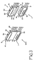
- the plug module 1 comprises on its face 30 mechanical coupling means constituted, for example, by dovetail-jointing means 51.
- the plug module 1 also comprises mechanical coupling means for connection to the electrical equipment positioned on its face 31.
- the plug module 3 comprises on its face 31 mechanical coupling means constituted, for example, by female dovetail-jointing means 53 that can be connected to the means 51 of the module 1.
- the plug module 3 further comprises mechanical coupling means for connection to the electrical equipment, constituted for example by a tooth 54 positioned on its face 30.
- the subset 200 has means 54 of mechanical coupling with the electrical equipment and, given the characteristics of modularity, may present a number of electrical connections, made up of the plugs 41 and the cables 42, which may vary according to the plug modules used for their construction.
- the plug modules 1 and 3, and consequently the subset 200, may moreover present mechanical coupling means, constituted for example by shaped guides 52, the function of which will be described in what follows.
- the same type of structure may be obtained also with socket modules.
- the subset 300 has means 54 for mechanical coupling with the electrical equipment and, given the characteristics of modularity, may present a number of electrical connections, made up of the sockets 43 and cables 42, which may vary according to the plug modules used for their construction.
- the socket modules 2 and 4, and consequently the subset 300 may moreover present mechanical coupling means, constituted for example by shaped guides 52, the function of which will be described in what follows. It is interesting to note that the subset 200 and the subset 300 can be electrically coupled together.
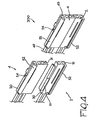
- connection device 5 envisages that the connection device 5 will be provided, both on the face 30 and on the face 31, with mechanical means for coupling with the electrical equipment, constituted for example by teeth 54 positioned on said faces 30 and 31.
- the height of said device 5 is equal to the height of the subset 200, the height being defined as the distance between the faces 30 and 31, on which the means 54 of mechanical coupling with the electrical equipment are positioned.
- connection device 5 is moreover preferably provided, in a position corresponding, for example, to one of the faces 21 of said second pair of faces 20 and 21, with mechanical means for coupling with a further connection device.
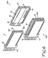
- These mechanical coupling means may be constituted, for example, by a groove 520, which can be coupled with a corresponding shaped guide 52, positioned, for example, on the face 20 of a device 1, 3 or of a subset 200. It may be seen from by Figure 5 how, via the mechanical coupling means 52 and 520, it is possible to obtain a subset 250, in which two or more modules are mechanically coupled together in a position corresponding to their faces 20, 21.
- the subset 250 is made up of the device 5 mechanically connected to the subset 200 in a position corresponding to the faces 20 and 21.
- the subset 200 is made up of the devices 1 and 3 mechanically connected together in a position corresponding to the faces 30, 31.
- the subset 250 has means 54 of mechanical coupling with the electrical equipment and, given the characteristics of modularity, may present a number of electrical connections, made up of the plugs 41 and cables 42, which may vary according to the plug modules used for its construction.
- socket modules may be coupled with a subset 300, thus producing a subset 360.
- the subset 360 has means 54 of mechanical coupling with the electrical equipment and, given the characteristics of modularity, may present a number of electrical connections, made up of the sockets 43 and cables 42, which may vary according to the plug modules used for their construction.
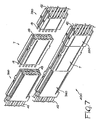
- FIG. 7 The modularity obtainable with the devices of the present invention is highlighted in Figure 7.
- Figure 7 it may be noted how in fact it is possible to vary the length of the subsets obtained, by means of the interposition of appropriate connection devices 7 having the function of adapter and/or extension.
- the device 7 between the subset 360 and the subset 250 there is obtained a subset 400 having a greater development in length, defining as length the distance between the faces 10 and 11, on which there are positioned the electrical coupling means 40.
- the mechanical coupling means 50 may for example be constituted by jointing means 51, 53, or else by sliding means 52, 520, or by other similar means.
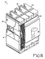
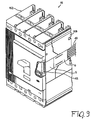
- connection devices according to the invention find adequate application in low-voltage equipment, such as for example circuit breakers, disconnectors and the like. Some examples of application are illustrated in Figures 8 to 13.
- a low-voltage apparatus for example a circuit breaker 15, is represented as a whole by a parallelepipedal structure having a front wall 150, a rear wall 151, a left-hand side wall 152, and a right-hand side wall 153.
- the terms "right-hand” and “left-hand” refer to a front view of the equipment.
- the devices according to the invention are advantageously housed in a seat 16 made in at least one of the side walls 151 and 152.
- the apparatus comprises at least one first connection device 5 operatively connected to one or more accessories of said apparatus via the cables 42.
- at least one second connection device 6 operatively connected to the electrical wiring system via one or more cables 42.
- the devices 5 and 6 are electrically coupled with one another and are mechanically coupled with the electrical apparatus, for example by means of interaction between the edges of the seat 16 and the teeth 54, as illustrated previously.
- Figure 10 shows a circuit breaker 15 equipped with a motor-driven control 18 positioned on its front wall 150, with the corresponding connection device 5 in the disconnected position.
- the use of the connection devices according to the invention is detailed in Figure 11, which presents an enlarged view of the portion of Figure 10 enclosed in the circle 80.
- Figure 10 it is possible to see a first connection device 1, operatively connected by means of the cables 42 to an accessory of the circuit breaker and installed within the seat 16 on the side wall 152 of said circuit breaker.
- a further connection device 3 mechanically coupled to the device 1.
- the device 3 is not operatively connected to any accessory and is used as adapter element, but it is in any case connectable to one or more accessories.
- the devices 3 and 4 constitute in practice a subset similar to the subset 200 of Figure 3, which can be coupled mechanically with the connection device 5.
- the device 5 is inserted in the seat 16 by mechanical coupling with the devices 1 and 3, and possibly also with the circuit breaker 15 and by electrical coupling with the device 6, for example by means of the insertion of the plugs 41 in the corresponding sockets 43.
- Figure 12 The final situation is illustrated in Figure 12, in which it may be seen how the motor-driven control is connected, through the devices 5 and 6 (positioned on the body of the circuit breaker) and the cables 42, to the part of wiring system pertaining thereto.
- FIG. 13 shows a circuit breaker 15 in the extractable version, installed on the corresponding element 19.
- at least one first connection device 1 is operatively connected to one or more accessories of the circuit breaker.
- a second connection device 2 is operatively connected to the electrical wiring system, whilst a third connection device 7 is set between said connection devices 1 and 2 in such a way that the first 1, second 2 and third 7 connection devices will be electrically coupled with one another and mechanically coupled with the circuit breaker.
- Figure 13 there are presented two further connection devices 3 and 4, mechanically coupled, respectively, to the devices 1 and 2.
- the devices 1 and 3 constitute a subset similar to the subset 200 illustrated in Figure 3, whilst the subsets 2 and 4 constitute a subset similar to the subset 300 of Figure 4.
- the assembly thus obtained between the devices 1, 3, 2, 4, and 7 constitutes a subset similar to the subset 400 of Figure 7.
- connection device according to the invention performs fully the intended task, as well as the intended purposes, providing significant advantages with respect to the known art.
- connection device according to its high characteristics of modularity it is easily possible to vary the number and/or the nature of the accessories present on a low-voltage apparatus, without having to resort to complicated and delicate operations of connection and wiring thereof.
- the presence of appropriate mechanical coupling in fact makes it possible to vary the height and/or the thickness of the subsets that may be made according to the needs of installation.
- the possibility of being able to have available adapter elements that make it possible to vary the height, thickness or length of the subsets enable standardization of the constructional characteristics of the circuit breaker, maintaining at the same time the advantages of the modular structure of the connection devices and hence the possibility of varying the number and the characteristics of the connections. Furthermore, it is possible to eliminate the presence of free or additional cables or plugs that might expose installation to the risk of erroneous connection or interfere in any way with other electrical or mechanical parts present on the switchboard.
- connection device thus conceived may undergo numerous modifications and variations, all falling within the scope of the inventive idea.
- shape of the modules could present a slightly different geometry, as well as the shape and the nature of the mechanical coupling means and/or electrical wiring may be of a different type with respect to what has been described herein.
- all the items may be replaced by other elements that are technically equivalent.
- the materials, as well as the dimensions may be any whatsoever, according to the requirements and the state of the art.
Landscapes
- Details Of Connecting Devices For Male And Female Coupling (AREA)
- Emergency Protection Circuit Devices (AREA)
- Coupling Device And Connection With Printed Circuit (AREA)
- Gas-Insulated Switchgears (AREA)
- Breakers (AREA)
- Connections Arranged To Contact A Plurality Of Conductors (AREA)
- Cable Accessories (AREA)
Applications Claiming Priority (2)
| Application Number | Priority Date | Filing Date | Title |
|---|---|---|---|
| ITBG20020042 | 2002-12-05 | ||
| IT000042A ITBG20020042A1 (it) | 2002-12-05 | 2002-12-05 | Dispositivo di connessione per apparecchiature di bassa tensione. |
Publications (3)
| Publication Number | Publication Date |
|---|---|
| EP1427059A1 true EP1427059A1 (de) | 2004-06-09 |
| EP1427059B1 EP1427059B1 (de) | 2008-02-27 |
| EP1427059B8 EP1427059B8 (de) | 2008-04-16 |
Family
ID=32310124
Family Applications (1)
| Application Number | Title | Priority Date | Filing Date |
|---|---|---|---|
| EP03078739A Expired - Lifetime EP1427059B8 (de) | 2002-12-05 | 2003-11-26 | Anordnung zum Anschliessen von Niederspannungsgeräten |
Country Status (7)
| Country | Link |
|---|---|
| US (1) | US6893298B2 (de) |
| EP (1) | EP1427059B8 (de) |
| CN (1) | CN100483856C (de) |
| AT (1) | ATE387733T1 (de) |
| DE (1) | DE60319326T2 (de) |
| ES (1) | ES2301757T3 (de) |
| IT (1) | ITBG20020042A1 (de) |
Families Citing this family (6)
| Publication number | Priority date | Publication date | Assignee | Title |
|---|---|---|---|---|
| US8354919B2 (en) * | 2008-01-16 | 2013-01-15 | Gallarzo Jose L | System and method for activating and deactivating a remotely controlled vehicle starter |
| CN101895073B (zh) * | 2009-05-21 | 2013-10-09 | 泰科电子(上海)有限公司 | 电源分配装置 |
| EP2491623B1 (de) | 2009-10-19 | 2019-12-04 | ADC Telecommunications, Inc. | Verwaltete elektrische konnektivitätssysteme |
| CN102412083A (zh) * | 2010-09-20 | 2012-04-11 | 西门子公司 | 一种用于隔离开关插入单元的侧板装置及其插入单元 |
| US9437954B2 (en) * | 2013-04-26 | 2016-09-06 | Interconnect Devices, Inc. | Series connector |
| TWM551769U (zh) * | 2017-07-28 | 2017-11-11 | Amphenol Fiber Optic Tech (Shenzhen) | 電源適配裝置 |
Citations (3)
| Publication number | Priority date | Publication date | Assignee | Title |
|---|---|---|---|---|
| US4597627A (en) * | 1980-03-28 | 1986-07-01 | Siemens Aktiengesellschaft | Multiple plug |
| DE19651961A1 (de) * | 1996-12-13 | 1998-06-18 | Siemens Ag | Elektrisches Gerät mit modularer Aufbautechnik |
| US6332813B1 (en) * | 1999-08-02 | 2001-12-25 | Yazaki Corporation | Joining structure of connector |
Family Cites Families (5)
| Publication number | Priority date | Publication date | Assignee | Title |
|---|---|---|---|---|
| GB1064113A (en) * | 1963-01-25 | 1967-04-05 | Plessey Uk Ltd | Improvements in or relating to plug-and-socket connectors |
| US4469393A (en) * | 1981-10-02 | 1984-09-04 | Westinghouse Electric Corp. | Modular connector |
| US5421746A (en) * | 1993-09-13 | 1995-06-06 | Berg Technology, Inc. | Orientation and positioning device for electrical connectors |
| US6206733B1 (en) * | 2000-04-18 | 2001-03-27 | Chih-Yuan Wu | Connection block assembly for a waterproof switch |
| DE20205787U1 (de) * | 2002-04-13 | 2002-07-25 | HARTING Electric GmbH & Co. KG, 32339 Espelkamp | Modularer Steckverbinder |
-
2002
- 2002-12-05 IT IT000042A patent/ITBG20020042A1/it unknown
-
2003
- 2003-11-24 US US10/718,592 patent/US6893298B2/en not_active Expired - Lifetime
- 2003-11-26 ES ES03078739T patent/ES2301757T3/es not_active Expired - Lifetime
- 2003-11-26 EP EP03078739A patent/EP1427059B8/de not_active Expired - Lifetime
- 2003-11-26 AT AT03078739T patent/ATE387733T1/de not_active IP Right Cessation
- 2003-11-26 DE DE60319326T patent/DE60319326T2/de not_active Expired - Lifetime
- 2003-12-04 CN CNB2003101246301A patent/CN100483856C/zh not_active Expired - Lifetime
Patent Citations (3)
| Publication number | Priority date | Publication date | Assignee | Title |
|---|---|---|---|---|
| US4597627A (en) * | 1980-03-28 | 1986-07-01 | Siemens Aktiengesellschaft | Multiple plug |
| DE19651961A1 (de) * | 1996-12-13 | 1998-06-18 | Siemens Ag | Elektrisches Gerät mit modularer Aufbautechnik |
| US6332813B1 (en) * | 1999-08-02 | 2001-12-25 | Yazaki Corporation | Joining structure of connector |
Also Published As
| Publication number | Publication date |
|---|---|
| ATE387733T1 (de) | 2008-03-15 |
| CN100483856C (zh) | 2009-04-29 |
| CN1521902A (zh) | 2004-08-18 |
| EP1427059B8 (de) | 2008-04-16 |
| DE60319326T2 (de) | 2009-03-26 |
| US6893298B2 (en) | 2005-05-17 |
| US20040110409A1 (en) | 2004-06-10 |
| DE60319326D1 (de) | 2008-04-10 |
| EP1427059B1 (de) | 2008-02-27 |
| ITBG20020042A1 (it) | 2004-06-06 |
| ES2301757T3 (es) | 2008-07-01 |
Similar Documents
| Publication | Publication Date | Title |
|---|---|---|
| EP2276332B1 (de) | Elektrisches System mit einer zurückziehbaren Einheit mit aufrechterhaltener Steuer- und Kommunikationsverbindung | |
| US7942692B2 (en) | Connecting element for the connection of switching devices | |
| CN101651067B (zh) | 用于抽出式断路器系统的辅助断开器 | |
| CN101536286B (zh) | 具有集成数字通信的中压或高压配电箱和用于该箱的多功能模块 | |
| US9564707B2 (en) | Connection system with modular expansion units having two or more devices | |
| KR100961776B1 (ko) | 모터 컨트롤 센터 | |
| CN101354988B (zh) | 可与断路器连接的剩余电流装置 | |
| KR100961777B1 (ko) | 전원분배모듈이 구비된 모터 컨트롤 센터 | |
| CN101295590A (zh) | 电气开关装置及其联锁相位屏障 | |
| EP3161914B1 (de) | Motorsteuerzentrale mit automatischer abgesicherte erdung der lastklemmen | |
| EP1427059B1 (de) | Anordnung zum Anschliessen von Niederspannungsgeräten | |
| CN101156289B (zh) | 开关设备模块的模块后壁、开关设备模块和电开关设备 | |
| EP1883941B1 (de) | Vorrichtung zur aufnahme und verbindung von zunbehören für schaltern | |
| JP2015050806A (ja) | 変電機器制御盤 | |
| US7262519B1 (en) | Actuator unit with at least two actuators and a secure control unit | |
| EP1346387B1 (de) | Stecksockel für schutzschalter | |
| US20240388043A1 (en) | Plug connector with fuse device, and assembly comprising such a plug connector | |
| EP2020669B1 (de) | Elektrischer Verbindungshilfsmodul für Schutzschalter | |
| US7679881B2 (en) | Electrical entity with opening of the load current circuit in an explosion-vulnerable environment | |
| KR101689948B1 (ko) | 정격식별을 위한 식별볼트를 구비하는 인입출형 진공차단기 | |
| KR101689947B1 (ko) | 정격식별을 위한 코드 플레이트를 구비하는 인입출형 진공차단기 | |
| EP3903391A1 (de) | Schalt- und/oder verteilvorrichtung |
Legal Events
| Date | Code | Title | Description |
|---|---|---|---|
| PUAI | Public reference made under article 153(3) epc to a published international application that has entered the european phase |
Free format text: ORIGINAL CODE: 0009012 |
|
| AK | Designated contracting states |
Kind code of ref document: A1 Designated state(s): AT BE BG CH CY CZ DE DK EE ES FI FR GB GR HU IE IT LI LU MC NL PT RO SE SI SK TR |
|
| AX | Request for extension of the european patent |
Extension state: AL LT LV MK |
|
| RAP1 | Party data changed (applicant data changed or rights of an application transferred) |
Owner name: ABB SERVICE S.R.L |
|
| 17P | Request for examination filed |
Effective date: 20041115 |
|
| AKX | Designation fees paid |
Designated state(s): AT BE BG CH CY CZ DE DK EE ES FI FR GB GR HU IE IT LI LU MC NL PT RO SE SI SK TR |
|
| 17Q | First examination report despatched |
Effective date: 20050210 |
|
| 17Q | First examination report despatched |
Effective date: 20050210 |
|
| GRAP | Despatch of communication of intention to grant a patent |
Free format text: ORIGINAL CODE: EPIDOSNIGR1 |
|
| GRAS | Grant fee paid |
Free format text: ORIGINAL CODE: EPIDOSNIGR3 |
|
| GRAA | (expected) grant |
Free format text: ORIGINAL CODE: 0009210 |
|
| AK | Designated contracting states |
Kind code of ref document: B1 Designated state(s): AT BE BG CH CY CZ DE DK EE ES FI FR GB GR HU IE IT LI LU MC NL PT RO SE SI SK TR |
|
| REG | Reference to a national code |
Ref country code: GB Ref legal event code: FG4D |
|
| REG | Reference to a national code |
Ref country code: CH Ref legal event code: EP |
|
| RAP2 | Party data changed (patent owner data changed or rights of a patent transferred) |
Owner name: ABB S.P.A. |
|
| REG | Reference to a national code |
Ref country code: IE Ref legal event code: FG4D |
|
| REF | Corresponds to: |
Ref document number: 60319326 Country of ref document: DE Date of ref document: 20080410 Kind code of ref document: P |
|
| REG | Reference to a national code |
Ref country code: CH Ref legal event code: NV Representative=s name: ISLER & PEDRAZZINI AG |
|
| REG | Reference to a national code |
Ref country code: SE Ref legal event code: TRGR |
|
| REG | Reference to a national code |
Ref country code: GR Ref legal event code: EP Ref document number: 20080401116 Country of ref document: GR |
|
| NLT2 | Nl: modifications (of names), taken from the european patent patent bulletin |
Owner name: ABB S.P.A. Effective date: 20080402 |
|
| REG | Reference to a national code |
Ref country code: ES Ref legal event code: FG2A Ref document number: 2301757 Country of ref document: ES Kind code of ref document: T3 |
|
| PG25 | Lapsed in a contracting state [announced via postgrant information from national office to epo] |
Ref country code: AT Free format text: LAPSE BECAUSE OF FAILURE TO SUBMIT A TRANSLATION OF THE DESCRIPTION OR TO PAY THE FEE WITHIN THE PRESCRIBED TIME-LIMIT Effective date: 20080227 |
|
| PG25 | Lapsed in a contracting state [announced via postgrant information from national office to epo] |
Ref country code: BE Free format text: LAPSE BECAUSE OF FAILURE TO SUBMIT A TRANSLATION OF THE DESCRIPTION OR TO PAY THE FEE WITHIN THE PRESCRIBED TIME-LIMIT Effective date: 20080227 Ref country code: SI Free format text: LAPSE BECAUSE OF FAILURE TO SUBMIT A TRANSLATION OF THE DESCRIPTION OR TO PAY THE FEE WITHIN THE PRESCRIBED TIME-LIMIT Effective date: 20080227 |
|
| PG25 | Lapsed in a contracting state [announced via postgrant information from national office to epo] |
Ref country code: SK Free format text: LAPSE BECAUSE OF FAILURE TO SUBMIT A TRANSLATION OF THE DESCRIPTION OR TO PAY THE FEE WITHIN THE PRESCRIBED TIME-LIMIT Effective date: 20080227 Ref country code: CZ Free format text: LAPSE BECAUSE OF FAILURE TO SUBMIT A TRANSLATION OF THE DESCRIPTION OR TO PAY THE FEE WITHIN THE PRESCRIBED TIME-LIMIT Effective date: 20080227 Ref country code: PT Free format text: LAPSE BECAUSE OF FAILURE TO SUBMIT A TRANSLATION OF THE DESCRIPTION OR TO PAY THE FEE WITHIN THE PRESCRIBED TIME-LIMIT Effective date: 20080721 Ref country code: DK Free format text: LAPSE BECAUSE OF FAILURE TO SUBMIT A TRANSLATION OF THE DESCRIPTION OR TO PAY THE FEE WITHIN THE PRESCRIBED TIME-LIMIT Effective date: 20080227 |
|
| ET | Fr: translation filed | ||
| PG25 | Lapsed in a contracting state [announced via postgrant information from national office to epo] |
Ref country code: RO Free format text: LAPSE BECAUSE OF FAILURE TO SUBMIT A TRANSLATION OF THE DESCRIPTION OR TO PAY THE FEE WITHIN THE PRESCRIBED TIME-LIMIT Effective date: 20080227 |
|
| PLBE | No opposition filed within time limit |
Free format text: ORIGINAL CODE: 0009261 |
|
| STAA | Information on the status of an ep patent application or granted ep patent |
Free format text: STATUS: NO OPPOSITION FILED WITHIN TIME LIMIT |
|
| 26N | No opposition filed |
Effective date: 20081128 |
|
| PG25 | Lapsed in a contracting state [announced via postgrant information from national office to epo] |
Ref country code: EE Free format text: LAPSE BECAUSE OF FAILURE TO SUBMIT A TRANSLATION OF THE DESCRIPTION OR TO PAY THE FEE WITHIN THE PRESCRIBED TIME-LIMIT Effective date: 20080227 Ref country code: BG Free format text: LAPSE BECAUSE OF FAILURE TO SUBMIT A TRANSLATION OF THE DESCRIPTION OR TO PAY THE FEE WITHIN THE PRESCRIBED TIME-LIMIT Effective date: 20080527 |
|
| PG25 | Lapsed in a contracting state [announced via postgrant information from national office to epo] |
Ref country code: MC Free format text: LAPSE BECAUSE OF NON-PAYMENT OF DUE FEES Effective date: 20081130 |
|
| PG25 | Lapsed in a contracting state [announced via postgrant information from national office to epo] |
Ref country code: CY Free format text: LAPSE BECAUSE OF FAILURE TO SUBMIT A TRANSLATION OF THE DESCRIPTION OR TO PAY THE FEE WITHIN THE PRESCRIBED TIME-LIMIT Effective date: 20080227 |
|
| PG25 | Lapsed in a contracting state [announced via postgrant information from national office to epo] |
Ref country code: IE Free format text: LAPSE BECAUSE OF NON-PAYMENT OF DUE FEES Effective date: 20081126 |
|
| PG25 | Lapsed in a contracting state [announced via postgrant information from national office to epo] |
Ref country code: LU Free format text: LAPSE BECAUSE OF NON-PAYMENT OF DUE FEES Effective date: 20081126 Ref country code: HU Free format text: LAPSE BECAUSE OF FAILURE TO SUBMIT A TRANSLATION OF THE DESCRIPTION OR TO PAY THE FEE WITHIN THE PRESCRIBED TIME-LIMIT Effective date: 20080828 |
|
| PGFP | Annual fee paid to national office [announced via postgrant information from national office to epo] |
Ref country code: GR Payment date: 20141125 Year of fee payment: 12 Ref country code: CH Payment date: 20141119 Year of fee payment: 12 Ref country code: FI Payment date: 20141112 Year of fee payment: 12 Ref country code: SE Payment date: 20141119 Year of fee payment: 12 |
|
| REG | Reference to a national code |
Ref country code: FR Ref legal event code: PLFP Year of fee payment: 13 |
|
| REG | Reference to a national code |
Ref country code: CH Ref legal event code: PL |
|
| PG25 | Lapsed in a contracting state [announced via postgrant information from national office to epo] |
Ref country code: GR Free format text: LAPSE BECAUSE OF NON-PAYMENT OF DUE FEES Effective date: 20160602 Ref country code: CH Free format text: LAPSE BECAUSE OF NON-PAYMENT OF DUE FEES Effective date: 20151130 Ref country code: LI Free format text: LAPSE BECAUSE OF NON-PAYMENT OF DUE FEES Effective date: 20151130 |
|
| PG25 | Lapsed in a contracting state [announced via postgrant information from national office to epo] |
Ref country code: SE Free format text: LAPSE BECAUSE OF NON-PAYMENT OF DUE FEES Effective date: 20151127 |
|
| REG | Reference to a national code |
Ref country code: GR Ref legal event code: ML Ref document number: 20080401116 Country of ref document: GR Effective date: 20160602 |
|
| REG | Reference to a national code |
Ref country code: FR Ref legal event code: PLFP Year of fee payment: 14 |
|
| PG25 | Lapsed in a contracting state [announced via postgrant information from national office to epo] |
Ref country code: FI Free format text: LAPSE BECAUSE OF NON-PAYMENT OF DUE FEES Effective date: 20151126 |
|
| REG | Reference to a national code |
Ref country code: FR Ref legal event code: PLFP Year of fee payment: 15 |
|
| PGFP | Annual fee paid to national office [announced via postgrant information from national office to epo] |
Ref country code: TR Payment date: 20221124 Year of fee payment: 20 Ref country code: NL Payment date: 20221118 Year of fee payment: 20 Ref country code: IT Payment date: 20221124 Year of fee payment: 20 Ref country code: GB Payment date: 20221125 Year of fee payment: 20 Ref country code: FR Payment date: 20221128 Year of fee payment: 20 Ref country code: DE Payment date: 20221123 Year of fee payment: 20 |
|
| PGFP | Annual fee paid to national office [announced via postgrant information from national office to epo] |
Ref country code: ES Payment date: 20230125 Year of fee payment: 20 |
|
| REG | Reference to a national code |
Ref country code: DE Ref legal event code: R071 Ref document number: 60319326 Country of ref document: DE |
|
| REG | Reference to a national code |
Ref country code: NL Ref legal event code: MK Effective date: 20231125 |
|
| REG | Reference to a national code |
Ref country code: ES Ref legal event code: FD2A Effective date: 20231201 |
|
| REG | Reference to a national code |
Ref country code: GB Ref legal event code: PE20 Expiry date: 20231125 |
|
| PG25 | Lapsed in a contracting state [announced via postgrant information from national office to epo] |
Ref country code: GB Free format text: LAPSE BECAUSE OF EXPIRATION OF PROTECTION Effective date: 20231125 |
|
| PG25 | Lapsed in a contracting state [announced via postgrant information from national office to epo] |
Ref country code: ES Free format text: LAPSE BECAUSE OF EXPIRATION OF PROTECTION Effective date: 20231127 |
|
| PG25 | Lapsed in a contracting state [announced via postgrant information from national office to epo] |
Ref country code: GB Free format text: LAPSE BECAUSE OF EXPIRATION OF PROTECTION Effective date: 20231125 Ref country code: ES Free format text: LAPSE BECAUSE OF EXPIRATION OF PROTECTION Effective date: 20231127 |