EP1427237A1 - Weiterreichungssteuervorrichtung, funkendgerät, edge-router, router, mobilkommunikationssystem und weiterreichungssteuerverfahren - Google Patents
Weiterreichungssteuervorrichtung, funkendgerät, edge-router, router, mobilkommunikationssystem und weiterreichungssteuerverfahren Download PDFInfo
- Publication number
- EP1427237A1 EP1427237A1 EP02765515A EP02765515A EP1427237A1 EP 1427237 A1 EP1427237 A1 EP 1427237A1 EP 02765515 A EP02765515 A EP 02765515A EP 02765515 A EP02765515 A EP 02765515A EP 1427237 A1 EP1427237 A1 EP 1427237A1
- Authority
- EP
- European Patent Office
- Prior art keywords
- router
- edge
- terminal unit
- radio terminal
- relay router
- Prior art date
- Legal status (The legal status is an assumption and is not a legal conclusion. Google has not performed a legal analysis and makes no representation as to the accuracy of the status listed.)
- Granted
Links
Images



Classifications
-
- H—ELECTRICITY
- H04—ELECTRIC COMMUNICATION TECHNIQUE
- H04W—WIRELESS COMMUNICATION NETWORKS
- H04W36/00—Hand-off or reselection arrangements
- H04W36/12—Reselecting a serving backbone network switching or routing node
-
- H—ELECTRICITY
- H04—ELECTRIC COMMUNICATION TECHNIQUE
- H04W—WIRELESS COMMUNICATION NETWORKS
- H04W36/00—Hand-off or reselection arrangements
- H04W36/10—Reselecting an access point controller
-
- H—ELECTRICITY
- H04—ELECTRIC COMMUNICATION TECHNIQUE
- H04W—WIRELESS COMMUNICATION NETWORKS
- H04W40/00—Communication routing or communication path finding
- H04W40/34—Modification of an existing route
- H04W40/36—Modification of an existing route due to handover
-
- H—ELECTRICITY
- H04—ELECTRIC COMMUNICATION TECHNIQUE
- H04W—WIRELESS COMMUNICATION NETWORKS
- H04W80/00—Wireless network protocols or protocol adaptations to wireless operation
Definitions
- the present invention relates to a handover control apparatus, a mobile communication system, and a handover control method configured to specify a relay router to be provided with the RR (Regional Registration) function, out of CORs (Cross Over Routers) under which edge routers provided in respective base stations for radio communication with radio terminal unit such as cellular phones and the like are connected, so as to preliminarily route an invariable path even after a handover, thereby decreasing a time period of the handover.
- RR Registered Registration
- CORs Cross Routers
- Fig. 4 is a block diagram for explaining the general handover operation in the conventional mobile communication systems.
- This mobile communication system shown in Fig. 4 is comprised of a plurality of base stations 16, 18, 20, 22 for radio communication with radio terminal units 12, 14 such as cellular phones, a plurality of routers 24, 26 connected above each of the base stations 16-22, a gateway device 28 connected above each of the routers 24, 26, and a CN (Correspondent Node) 30 which is a communication terminal unit of a correspondent party connected through a communication network to the gateway device 28.
- radio terminal units 12, 14 such as cellular phones
- a plurality of routers 24, 26 connected above each of the base stations 16-22
- a gateway device 28 connected above each of the routers 24, 26, and a CN (Correspondent Node) 30 which is a communication terminal unit of a correspondent party connected through a communication network to the gateway device 28.
- CN Correspondent Node
- the radio terminal unit 12 presently under communication with the base station 16 evaluates the condition of radio waves from the destination base station 18 and initiates a handover transaction.
- the radio terminal unit 12 transmits a movement notification message, as indicated by an arrow Y1, through the destination base station 18, router 24, and gateway device 28 to the CN 30 of the communication correspondent.
- the CN 30 transmits an acknowledgment as indicated by an arrow Y2 and the radio terminal unit receives the acknowledgment and thereafter receives data packets transmitted from the CN 30.
- the radio terminal unit 14 first detects fade away of a radio link with the base station 20 where it is presently registered, and thereafter initiates a handover transaction.
- the radio terminal unit 14 transmits a movement notification message, as indicated by an arrow Y3, through the destination base station 22, router 26, and gateway device 28 to the CN 30 of the communication correspondent.
- the CN 30 transmits an acknowledgment as indicated by an arrow Y4, and the radio terminal unit receives the acknowledgment and then receives data packets transmitted from the CN 30 of the communication correspondent.
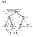
- relay routers 24a, 26a are introduced into the domain and movement under command of the relay routers 24a, 26a is supported by change of location registration in the relay routers 24a, 26a.
- the relay router 24a performs path rerouting. Namely, the relay router 24a performs path rerouting from a path 42 of connection between the relay router 24a and the edge router 16a to a path 44 of connection between the relay router 24a and the edge router 18a. At this time, no change is made in a path 46 of connection between the CN 30 and the relay router 24a.
- the radio terminal unit 12 has moved from the edge router 18a to the edge router 20a as indicated by an arrow Y12.
- the radio terminal unit 12 since there is the difference between the relay routers connected to the previous edge router 18a and to the new edge router 20a, i.e., between 24a and 26a, the radio terminal unit 12 notifies the CN 30 of the communication correspondent of the change of the relay router to 26a, as indicated by an arrow Y13.
- the path from the CN 30 through the gateway device 28 to the relay router is rerouted from the path 46 of connection between the CN 30 and the relay router 24a to a path 48 of connection between the CN 30 and the relay router 26a, and a path from the relay router 26a to the radio terminal unit 12 has to be a path 50 of connection from the relay router 26a through the edge router 20a to the radio terminal unit 12.
- all the paths from the CN 30 to the radio terminal unit 12 need to be rerouted.
- An object of the present invention is therefore to provide a handover control apparatus, a radio terminal unit, an edge router, a router, a mobile communication system, and a handover control method capable of readily decreasing the handover transaction time by obviating the need for the path rerouting up to CN 30 of the communication correspondent at the time of handover.
- a handover control apparatus of the present invention is a handover control apparatus for controlling handover of a radio terminal unit between edge routers which are provided in respective base stations for radio communication with radio terminal unit and to which routers are connected above in a hierarchical structure, the handover control apparatus comprising: control means for specifying a relay router out of CORs where all paths from an edge router before movement of the radio terminal unit and from every edge router as a candidate for a destination of the movement to a communication correspondent intersect.
- a mobile communication system of the present invention is a mobile communication system for implementing handover of a radio terminal unit between base stations, the mobile communication system comprising: routers connected above the base stations in a hierarchical structure and configured to perform relaying of data to the base stations; and edge routers provided in the respective base stations, each edge router being configured to specify a relay router out of CORs where all paths from a base station before movement of the radio terminal unit and from every base station as a candidate for a destination of the movement to a communication correspondent intersect.
- a handover control method of the present invention is a handover control method of controlling handover of a radio terminal unit between edge routers which are provided in respective base stations for radio communication with radio terminal unit and to which routers are connected above in a hierarchical structure, the handover control method comprising: a control step of specifying a relay router out of CORs where all paths from an edge router before movement of the radio terminal unit and from every edge router as a candidate for a destination of the movement to a communication correspondent intersect.
- This configuration makes it feasible to specify the common relay router to the edge router currently under connection with the radio terminal unit and every edge router as a destination candidate, whereby the handover can be performed by only sending the location change notification to the thus specified relay router. Namely, the handover can be performed without sending the location change notification up to the communication correspondent as before, so that the time period of the handover transaction can be readily reduced.
- Fig. 1 is a block diagram showing a configuration of a mobile communication system according to an embodiment of the present invention.
- This mobile communication system shown in Fig. 1 is comprised of a plurality of edge routers 102, 104, 106, 108, 110, 112, 114, 116 provided in respective base stations for radio communication with radio terminal unit 100 such as a cellular phone or the like, a plurality of routers 118, 120, 122, 124 connected above the edge routers 102-116, routers 126, 128 each connected above these routers 118-124, a gateway device 130 connected above each of the routers 126, 128, and a CN 132 which is a communication terminal unit of a correspondent party connected through a communication network to the gateway device 130.
- Each of the edge routers 102-116 stores information about locations of edge routers mounted in base stations forming radio zones adjacent to a radio zone of a base station in which the edge router in question is mounted, and information about locations of superordinate routers to which these adjacent edge routers and the edge router in question are connected.
- the radio terminal unit 100 presently connected to the edge router 102 moves, it is expected from the location information stored in the edge router 102 before the movement that the edge router 104 will be a candidate for the destination of the movement and the radio terminal unit 100 will move to the edge router 104.
- CORs are the superordinate routers 118 and 126 and gateway device 130 connected to the destination candidate edge router 104.
- a COR is a router under which all edge routers as potential handover destinations are located, and router on a path to the communication correspondent.
- the gateway device 130 can also be considered to be one router.
- a relay router is specified out of the above CORs by making use of information about applications used by the user, the load on the network, radio technology, and so on.
- the relay router is a router as an origin of switching of path. Namely, location information of a radio terminal unit under command is registered in the relay router and data addressed to the radio terminal unit is tunneled at the relay router to be forwarded to the radio terminal unit.
- a location update message can be received faster by locating the RR function in the COR closer to the radio terminal unit 100 (i.e., by determining the COR closer to the radio terminal unit 100 as a relay router).
- the router 118 being the COR closer to the radio terminal unit is specified as a relay router, out of the CORs where all the paths from the edge router 102 being the edge router before the movement of the radio terminal unit 100 and from the edge router 104 as a destination candidate to the CN 132 being the terminal unit of the correspondent party intersect, and the RR function is located in the router 118.
- the RR function (Regional Registration function) is a function of recording location information of radio terminal unit and forwarding data to a specific radio terminal unit on the basis of the location information.
- destination candidates are the edge routers 102 and 106.
- the router 118 is connected above the edge router 102 and the router 120 is connected above the edge router 106, a common router connected to the both edge routers 102 and 106 is a much higher router 126.
- the router 126 and gateway device 130 are CORs where all the paths from the edge routers 102 and 106 to the CN 132 of the correspondent terminal unit intersect.
- the router 118 or 120 above each edge router 102 or 106 can also be defined as a candidate of COR.
- the relay router is specified out of the above CORs by making use of the applications used by the user, the load on the network, the radio technology, etc. as described previously. If the information about the applications used by the user, the load on the network, the radio technology, etc. as described is not available, the router 126 being the COR closer to the radio terminal unit is specified as a relay router, out of the CORs where all the paths from the edge router 104 being the edge router before the movement of the radio terminal unit 100 and from each of the edge routers 102, 106 being the destination candidates to the CN 132 being the correspondent terminal unit intersect, and the RR function is located in the router 126.
- the radio terminal unit 100 presently connected to the edge router 106 moves to the edge router 108 as indicated by an arrow Y15.
- the destination candidates are the edge routers 104 and 108, and the router 126 is thus selected as a relay router; the CN 132 of the communication correspondent is notified of the location information of the router 126 being the relay router.
- the radio terminal unit 100 moves to the edge router 108 and then sends a location change notification to the router 126 being the relay router. Then, without any change in the path from the CN 132 to the router 126, the path from the router 126 to the radio terminal unit 100 is switched from a path 140 via the edge router 106 to a path 142 via the edge router 108.
- the relay router herein Since the location of the relay router herein is closer than the CN 132 of the communication correspondent, it also becomes feasible to decrease the time for location registration and thus decrease the time period necessary for the handover transaction.
- the destination candidates thereafter are the edge routers 106 and 110, and the gateway device 130 is selected as a relay router. Since the selected gateway device 130 is different from the router 126 being the previous relay router before the movement, it is necessary to move the relay router from the router 126 to the gateway device 130. Therefore, the radio terminal unit 100 sends an RR instruction to the gateway device 130.
- the RR instruction (Regional Registration instruction) is an instruction to make a specific router function as a relay router.
- the CN 132 of the communication correspondent is immediately notified that the gateway device 130 became a new relay router. This process is not carried out during the handover, but is carried out after completion of the handover transaction. However, packets are sent via the router 126 even during the period in which the CN 132 of the communication correspondent is notified that the relay router is the gateway device 130, and thus this process invokes no short break of communication. After the above notification to the CN 132, the path from CN 132 to the gateway device 130 is established and the path from the gateway device 130 to the radio terminal unit 100 is further established.
- the mobile communication system of the present embodiment is constructed in the configuration wherein there are the routers 118-128 and gateway device 130 connected above the edge routers 102-116 provided in the respective base stations in the hierarchical structure and configured to perform the relaying of data to the base stations and wherein the router 126 being the COR closer to the radio terminal unit 100 is specified as a relay router, out of the CORs where all the paths from the edge router 104 before the movement of the radio terminal unit 100 and from each of all the edge routers 102, 106 being destination candidates to the CN 132 of the communication correspondent intersect.
- the handover can be performed by only sending the location change notification to the specified relay router 126. Namely, the handover can be performed without sending the location change notification up to the CN 132 of the communication correspondent as before, so that the handover transaction time can be readily reduced.
- the edge routers 102-116 each are provided with the function of storing the information about the edge routers mounted in the base stations forming the radio zones adjacent to the radio zone of the base station in which the edge router in question is mounted, and the information about the superordinate routers to which these adjacent edge routers and edge router in question are connected, and specifying the router where all the paths intersect, as a COR from the stored information. This makes it feasible to readily specify the COR.
- the radio terminal unit 100 can access the relay router through the destination edge router during the period of the handover.
- the RR function is located in the router 126 being the COR closer to the radio terminal unit 100, as a relay router, and the communication correspondent of the radio terminal unit 100 is notified of the location information of the relay router 126 where the RR function is located.
- the communication correspondent is preliminarily notified of the location to the relay router in which the location registration relaying function is located, and the radio terminal unit can change the location by simply sending a location registration request to the relay router to update the path after movement; therefore, the handover transaction time can be reduced, as compared with the case where the location change notification is sent to the communication correspondent.
- the location registration relaying function is located in another relay router 130; therefore, the location registration relaying point can be properly changed after the movement of the radio terminal unit 100.
- the number of edge routers as potential destinations can be narrowed down if the information about radio links, the information about the moving direction of the terminal, or the like is available; then the relay router as a relay node can be located at a COR closer to the terminal, whereby the handover transaction time can be reduced more.
- the radio resources are expected to become more stringent, for example, because the frequency bands become higher, so as to narrow the area covered by one base station. Under such circumstances, if the time for each handover transaction can be reduced, the overlap zone can be narrowed and it can lead to effective utilization of the radio resources.
- the mobile communication system in the above embodiment was constructed in the configuration wherein the radio terminal unit 100 was notified of the information about the relay router, the radio terminal unit 100 sent the RR instruction to the COR specified as the relay router, on the basis of the information, and the COR provided the RR function on the basis of the RR instruction transmitted from the radio terminal unit 100.
- this may be modified into such a configuration that the edge router transmits the RR instruction to the COR specified as the relay router and the COR provides the RR function on the basis of the RR instruction transmitted from the edge router.
- the handover operation in the case adopting this configuration will be described below.
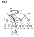
- Fig. 3 is a block diagram for explaining the handover operation in the case adopting the above configuration.
- the information about relay routers corresponding to the respective edge routers 102-116 is preliminarily stored in each of the edge routers 102-116.
- destination candidates for movement of the mobile terminal unit 100 under the edge router 106 are the edge routers 104, 108 from the network configuration (including the location information) shown in Fig. 3. Therefore, the router 126 closer to the radio terminal unit 100 is specified as a relay router, out of the CORs (router 126 and gateway device 130) where all the paths from the edge router 106 before the movement and from each of the edge routers 104, 108 as destination candidates to the CN 132 intersect. In this case, the information that the router 126 was specified as a relay router is recorded in the edge router 106.
- the gateway device 130 which is a COR where all the paths from the edge router 108 before the movement and from each of the edge routers 106, 110 as destination candidates to the CN 132 of the communication correspondent intersect, is specified as a relay router.
- the information that the gateway device 130 was specified as a relay router is recorded in the edge router 108.
- the edge router 108 transmits a location change notification (Y19) to the router 126 being the old relay router to reroute the path from Y16 to Y17, in order to change the path between the radio terminal unit 100 having moved from the edge router 106 and the CN 132 of the communication correspondent.
- the edge router 108 transmits an RR instruction (Y20) to the gateway device 130 specified as a relay router, on the basis of the information of the relay router preliminarily recorded, to reroute the path from Y17 to Y18.
- the gateway device 130 receiving the RR instruction, provides the RR function from then on as a relay router.
- This configuration obviates the need for notifying the radio terminal unit 100 of the information of the relay router and for informing the user (radio terminal unit 100) of the network configuration, and thus the network configuration can be blocked off.
- the present invention is applicable to mobile communication systems and, particularly, to the handover control apparatus, radio terminal unit, edge routers, routers, and handover control methods in the mobile communication systems.
Landscapes
- Engineering & Computer Science (AREA)
- Computer Networks & Wireless Communication (AREA)
- Signal Processing (AREA)
- Mobile Radio Communication Systems (AREA)
- Data Exchanges In Wide-Area Networks (AREA)
Applications Claiming Priority (3)
| Application Number | Priority Date | Filing Date | Title |
|---|---|---|---|
| JP2001277127A JP4108950B2 (ja) | 2001-09-12 | 2001-09-12 | ハンドオーバ制御装置、無線端末機、エッジルータ、ルータ、移動通信システム及びハンドオーバ制御方法 |
| JP2001277127 | 2001-09-12 | ||
| PCT/JP2002/009369 WO2003026336A1 (en) | 2001-09-12 | 2002-09-12 | Handover control apparatus, radio terminal device, edge router, router, mobile communication system, and handover control method |
Publications (4)
| Publication Number | Publication Date |
|---|---|
| EP1427237A1 true EP1427237A1 (de) | 2004-06-09 |
| EP1427237A4 EP1427237A4 (de) | 2008-03-19 |
| EP1427237B1 EP1427237B1 (de) | 2010-04-28 |
| EP1427237B9 EP1427237B9 (de) | 2010-09-01 |
Family
ID=19101708
Family Applications (1)
| Application Number | Title | Priority Date | Filing Date |
|---|---|---|---|
| EP20020765515 Expired - Lifetime EP1427237B9 (de) | 2001-09-12 | 2002-09-12 | Weiterreichungssteuervorrichtung, Funkendgerät, Edge-Router, Router, Mobilkommunikationssystem und Weiterreichungssteuerverfahren |
Country Status (6)
| Country | Link |
|---|---|
| US (1) | US7519367B2 (de) |
| EP (1) | EP1427237B9 (de) |
| JP (1) | JP4108950B2 (de) |
| CN (2) | CN1262144C (de) |
| DE (1) | DE60236176D1 (de) |
| WO (1) | WO2003026336A1 (de) |
Cited By (1)
| Publication number | Priority date | Publication date | Assignee | Title |
|---|---|---|---|---|
| EP1521494A3 (de) * | 2003-09-30 | 2005-09-07 | Nokia Corporation | Verfahren und Funknetzwerk zum Verteilen der "Macro-Diversity-Combining"-Verarbeitung für Soft Handover |
Families Citing this family (13)
| Publication number | Priority date | Publication date | Assignee | Title |
|---|---|---|---|---|
| JP3924480B2 (ja) * | 2002-03-06 | 2007-06-06 | 株式会社エヌ・ティ・ティ・ドコモ | ハンドオーバ制御装置、中継ルータ、ゲートウェイ装置、アクセスルータ、基地局、移動通信システム、及びハンドオーバ制御方法 |
| US7649866B2 (en) * | 2003-06-24 | 2010-01-19 | Tropos Networks, Inc. | Method of subnet roaming within a network |
| KR100521440B1 (ko) * | 2003-12-27 | 2005-10-13 | 동부아남반도체 주식회사 | n채널형 모스 트랜지스터의 할로 영역 형성 방법 |
| US7693513B2 (en) * | 2005-01-18 | 2010-04-06 | Intel Corporation | Methods and apparatus for transferring service flow context of mobile broadband wireless access networks |
| CN1943190B (zh) * | 2005-03-08 | 2011-08-31 | 日本电信电话株式会社 | 洪泛抑制方法 |
| EP1863229A4 (de) * | 2005-03-25 | 2012-04-04 | Nec Corp | Mobilkommunikationssystem, edge-router, darin verwendetes mobilverwaltungsverfahren, programm und aufzeichnungsmedium |
| KR100703416B1 (ko) | 2005-07-06 | 2007-04-03 | 삼성전자주식회사 | 통신 시스템에서 네트워크 재진입 절차 수행 완료 통보 시스템 및 방법 |
| US20090207782A1 (en) * | 2005-10-07 | 2009-08-20 | Matsushita Electric Industrial Co., Ltd. | Aggregation management system, aggregate node, and deaggregate node |
| JP4848890B2 (ja) * | 2006-08-23 | 2011-12-28 | 日本電気株式会社 | 移動通信システム及びその方法並びにそれに用いる基地局 |
| CN102638786B (zh) | 2006-09-06 | 2015-01-21 | 夏普株式会社 | 通信系统、通信控制方法、中继装置、移动终端 |
| JP5366579B2 (ja) * | 2009-02-09 | 2013-12-11 | キヤノン株式会社 | 通信システム、通信装置、その処理方法及びプログラム |
| US20110238242A1 (en) * | 2010-03-29 | 2011-09-29 | Invensys Rail Corporation | Synchronization to adjacent wireless networks using single radio |
| US10638376B2 (en) * | 2014-03-04 | 2020-04-28 | Nokia Solutions And Networks Management International Gmbh | RAN based gateway functions |
Family Cites Families (12)
| Publication number | Priority date | Publication date | Assignee | Title |
|---|---|---|---|---|
| JP2946517B2 (ja) | 1989-02-03 | 1999-09-06 | 日本電気株式会社 | ルーティング方式およびルーティング表更新方式 |
| SG43752A1 (en) | 1993-01-21 | 1997-11-14 | At & T Corp | Directory structure for large scale telecommunications network allowing location of roaming mobile subcribers |
| US5974036A (en) * | 1996-12-24 | 1999-10-26 | Nec Usa, Inc. | Handoff-control technique for wireless ATM |
| US6131030A (en) * | 1998-08-19 | 2000-10-10 | Telefonaktiebolaget Lm Ericsson | System network and method for the transference of cell handover information |
| US6643279B1 (en) * | 1998-09-01 | 2003-11-04 | Nec Corporation | Handoff control for point to multipoint connections in mobile ATM networks |
| JP3239859B2 (ja) * | 1998-09-24 | 2001-12-17 | 日本電気株式会社 | 移動体通信システム及びその通信方法 |
| US7239618B1 (en) | 1998-12-11 | 2007-07-03 | Lucent Technologies Inc. | Single phase local mobility scheme for wireless access to packet-based networks |
| US6434134B1 (en) * | 1998-12-11 | 2002-08-13 | Lucent Technologies, Inc. | Dynamic address assignment for wireless devices accessing packet-based wired networks |
| JP2000324169A (ja) * | 1999-05-13 | 2000-11-24 | Nippon Telegr & Teleph Corp <Ntt> | ルーチング処理方法 |
| JP3589089B2 (ja) * | 1999-05-27 | 2004-11-17 | 株式会社エヌ・ティ・ティ・ドコモ | 通信プロトコル代行処理方法、通信プロトコル代行処理装置、及び通信プロトコル代行処理サービス装置 |
| JP2001045534A (ja) * | 1999-07-28 | 2001-02-16 | Ntt Docomo Inc | クラスタ構造形移動通信システム、基地局、クラスタ統括局、回線制御局及び移動局 |
| US7158497B2 (en) * | 2000-08-31 | 2007-01-02 | Nortel Networks Limited | Methods and apparatus for supporting micro-mobility within a radio access network |
-
2001
- 2001-09-12 JP JP2001277127A patent/JP4108950B2/ja not_active Expired - Fee Related
-
2002
- 2002-09-12 WO PCT/JP2002/009369 patent/WO2003026336A1/ja not_active Ceased
- 2002-09-12 EP EP20020765515 patent/EP1427237B9/de not_active Expired - Lifetime
- 2002-09-12 CN CNB028027027A patent/CN1262144C/zh not_active Expired - Fee Related
- 2002-09-12 US US10/416,339 patent/US7519367B2/en not_active Expired - Fee Related
- 2002-09-12 DE DE60236176T patent/DE60236176D1/de not_active Expired - Lifetime
- 2002-09-12 CN CNA2006100927982A patent/CN1964563A/zh not_active Withdrawn
Cited By (1)
| Publication number | Priority date | Publication date | Assignee | Title |
|---|---|---|---|---|
| EP1521494A3 (de) * | 2003-09-30 | 2005-09-07 | Nokia Corporation | Verfahren und Funknetzwerk zum Verteilen der "Macro-Diversity-Combining"-Verarbeitung für Soft Handover |
Also Published As
| Publication number | Publication date |
|---|---|
| EP1427237B9 (de) | 2010-09-01 |
| JP2003087841A (ja) | 2003-03-20 |
| EP1427237A4 (de) | 2008-03-19 |
| US7519367B2 (en) | 2009-04-14 |
| CN1511426A (zh) | 2004-07-07 |
| WO2003026336A1 (en) | 2003-03-27 |
| JP4108950B2 (ja) | 2008-06-25 |
| CN1964563A (zh) | 2007-05-16 |
| EP1427237B1 (de) | 2010-04-28 |
| US20040063429A1 (en) | 2004-04-01 |
| DE60236176D1 (de) | 2010-06-10 |
| CN1262144C (zh) | 2006-06-28 |
Similar Documents
| Publication | Publication Date | Title |
|---|---|---|
| EP1400132B1 (de) | Protokoll zur bestimmung von optimal-ziel-zugriffsroutern für eine nahtlose weiterreichung auf ip-ebene | |
| US6539225B1 (en) | Seamless data network telecommunication service during mobile wireless call handoff | |
| US7519367B2 (en) | Handover control apparatus, radio terminal device, edge router, router, mobile communication system, and handover control method | |
| US7843880B2 (en) | Mobile terminal device and hand-off method thereof | |
| US20040082330A1 (en) | Method for handoff and redundancy using mobile IP | |
| CN101305637B (zh) | 电信装置和方法 | |
| WO2001099458A1 (en) | A method for performing a mobile user terminal route update in a telecommunication network operated based on the internet protocol | |
| KR20010030116A (ko) | 통신 세션의 핸드오프를 위한 방법, 시스템 및 장치 | |
| CN103931235A (zh) | WiFi-DECT无线电信网络中的用于改变与终端相关联的无线接入点的方法 | |
| JP2007096522A (ja) | 無線接続方式 | |
| US8223684B2 (en) | Mobile communication system, gateway, concentrator, and handover control method | |
| US7181219B2 (en) | Wireless handover using anchor termination | |
| US20060293053A1 (en) | Silent wireless communication system and method | |
| US7907584B2 (en) | Access router device, mobility control system, and mobility control method | |
| EP1604531B1 (de) | Schnelles weiterreichen in mobilen kommunikationsnetzwerken | |
| CN1750710B (zh) | 用于具有重叠区域的下一代移动通信系统的切换方法 | |
| EP2043378A1 (de) | Verfahren zur steuerung von ms- und ganc-registrierungen | |
| US20070249357A1 (en) | Method for Switching Between Two Telephone Services | |
| JP4325674B2 (ja) | 無線通信システム、移動局、ハンドオーバ制御方法 | |
| Tsubouchi et al. | Anchorless routing for URLLC services in 5G network | |
| JPH0215722A (ja) | 通信中チャネル切替方式 | |
| JP6425253B2 (ja) | コアネットワーク分散型無線通信システム及びそのコネクション制御方法 | |
| EP3471461A1 (de) | Mobiles ip-steuerungssystem, mobiles ip-steuerungsverfahren und mobiles ip-steuerungsprogramm | |
| JP3184173B2 (ja) | 移動体位置登録方式 | |
| JP2541134B2 (ja) | ホ―ムメモリのル―チング番号更新方式 |
Legal Events
| Date | Code | Title | Description |
|---|---|---|---|
| PUAI | Public reference made under article 153(3) epc to a published international application that has entered the european phase |
Free format text: ORIGINAL CODE: 0009012 |
|
| 17P | Request for examination filed |
Effective date: 20030516 |
|
| AK | Designated contracting states |
Kind code of ref document: A1 Designated state(s): AT BE BG CH CY CZ DE DK EE ES FI FR GB GR IE IT LI LU MC NL PT SE SK TR |
|
| A4 | Supplementary search report drawn up and despatched |
Effective date: 20080219 |
|
| 17Q | First examination report despatched |
Effective date: 20090319 |
|
| RIC1 | Information provided on ipc code assigned before grant |
Ipc: H04W 36/12 20090101AFI20090813BHEP |
|
| RTI1 | Title (correction) |
Free format text: HANDOVER CONTROL APPARATUS, RADIO TERMINAL DEVICE, EDGE ROUTER, ROUTER, MOBILE COMMUNICATION SYSTEM AND HANDOVER CONTROL METHOD |
|
| GRAP | Despatch of communication of intention to grant a patent |
Free format text: ORIGINAL CODE: EPIDOSNIGR1 |
|
| RTI1 | Title (correction) |
Free format text: HANDOVER CONTROL APPARATUS, RADIO TERMINAL DEVICE, EDGE ROUTER, ROUTER, MOBILE COMMUNICATION SYSTEM AND HANDOVER CONTROL METHOD |
|
| GRAS | Grant fee paid |
Free format text: ORIGINAL CODE: EPIDOSNIGR3 |
|
| RIN1 | Information on inventor provided before grant (corrected) |
Inventor name: ISOBE, SHINICHI,NTT DOCOMO INC. INT. PROP. DEPT. Inventor name: IGARASHI, KEN,C/O INT PROPERTY DEPT, Inventor name: IWASAKI, ATSUSHI,NTT DOCOMO INC. INT. PROP. DEPT. |
|
| RIN1 | Information on inventor provided before grant (corrected) |
Inventor name: IWASAKI, ATSUSHI Inventor name: ISOBE, SHINICHI Inventor name: IGARASHI, KEN |
|
| GRAA | (expected) grant |
Free format text: ORIGINAL CODE: 0009210 |
|
| AK | Designated contracting states |
Kind code of ref document: B1 Designated state(s): DE GB |
|
| REG | Reference to a national code |
Ref country code: GB Ref legal event code: FG4D |
|
| REF | Corresponds to: |
Ref document number: 60236176 Country of ref document: DE Date of ref document: 20100610 Kind code of ref document: P |
|
| PLBE | No opposition filed within time limit |
Free format text: ORIGINAL CODE: 0009261 |
|
| STAA | Information on the status of an ep patent application or granted ep patent |
Free format text: STATUS: NO OPPOSITION FILED WITHIN TIME LIMIT |
|
| 26N | No opposition filed |
Effective date: 20110131 |
|
| PGFP | Annual fee paid to national office [announced via postgrant information from national office to epo] |
Ref country code: DE Payment date: 20170905 Year of fee payment: 16 Ref country code: GB Payment date: 20170906 Year of fee payment: 16 |
|
| REG | Reference to a national code |
Ref country code: DE Ref legal event code: R119 Ref document number: 60236176 Country of ref document: DE |
|
| GBPC | Gb: european patent ceased through non-payment of renewal fee |
Effective date: 20180912 |
|
| PG25 | Lapsed in a contracting state [announced via postgrant information from national office to epo] |
Ref country code: DE Free format text: LAPSE BECAUSE OF NON-PAYMENT OF DUE FEES Effective date: 20190402 |
|
| PG25 | Lapsed in a contracting state [announced via postgrant information from national office to epo] |
Ref country code: GB Free format text: LAPSE BECAUSE OF NON-PAYMENT OF DUE FEES Effective date: 20180912 |