EP1428005B1 - Methode und einrichtung zur dynamischen auswuchtung einer rotierenden struktur - Google Patents
Methode und einrichtung zur dynamischen auswuchtung einer rotierenden struktur Download PDFInfo
- Publication number
- EP1428005B1 EP1428005B1 EP02779347A EP02779347A EP1428005B1 EP 1428005 B1 EP1428005 B1 EP 1428005B1 EP 02779347 A EP02779347 A EP 02779347A EP 02779347 A EP02779347 A EP 02779347A EP 1428005 B1 EP1428005 B1 EP 1428005B1
- Authority
- EP
- European Patent Office
- Prior art keywords
- balancing
- signals
- vibration
- balancing devices
- processing
- Prior art date
- Legal status (The legal status is an assumption and is not a legal conclusion. Google has not performed a legal analysis and makes no representation as to the accuracy of the status listed.)
- Expired - Lifetime
Links
Images


Classifications
-
- G—PHYSICS
- G01—MEASURING; TESTING
- G01M—TESTING STATIC OR DYNAMIC BALANCE OF MACHINES OR STRUCTURES; TESTING OF STRUCTURES OR APPARATUS, NOT OTHERWISE PROVIDED FOR
- G01M1/00—Testing static or dynamic balance of machines or structures
- G01M1/30—Compensating imbalance
- G01M1/36—Compensating imbalance by adjusting position of masses built-in the body to be tested
Definitions
- the present invention relates to a method for the dynamic balancing of a rotatable structure rotating about a longitudinal axis, by means of an apparatus including two vibration-detecting sensors, two associated balancing devices, and processing and control means adapted for processing signals output from the two vibration-detecting sensors and for controlling the balancing devices, the method including the steps of arranging each vibration-detecting sensor and its associated balancing device near a checking section, the two checking sections being spaced out along the longitudinal axis, and controlling the operation of the balancing devices on the basis of the signals of the two vibration-detecting sensors.
- the invention also relates to an apparatus for implementing said method.
- Undesired vibrations are generally present in a grinding machine, and generated by out-of-balance conditions of the grinding wheel due to various possible reasons depending on the grinding wheel itself, like shape and/or constitution defects (inhomogeneity of the materials, concentricity errors between the external abrading surface and the internal centering hole, etc.), inaccurate assembling to the rotating spindle (hence causing the wheel center of gravity to be spaced apart from the axis of rotation), and, in general, deteriorations due to wear and/or splinter occurring during the machining of the workpieces. These vibrations may cause inaccuracies in the features of the machined workpieces - more specifically roundness errors like ovality and/or lobing - and introduce loads and stresses that may damage the machine tool.
- balancing apparatuses or balancers
- the driving motors are also part of the apparatus, rotate along with it and the grinding wheel, and are power supplied and controlled by a stationary external power source, by means of an electric connection, including, for example, a brush collector and slip rings, or by means of a contactless connection, for example of the inductive type.
- the characteristics (like, for example, the amplitude) of the vibrations generated as a consequence of the out-of-balance are picked up by processing the signals provided by an appropriate sensor and displayed, or processed in a proper unit (that often comprises the previously mentioned power supply source, too) for providing suitable balancing signals and for controlling the motors to drive the movable masses.
- the automatic balancing of grinding wheels generally takes place in a heuristic way, i.e. on the basis of cycles for displacing the two masses in the balancing device in order to continuously reduce the vibration detected by the sensor until there is obtained its complete elimination or in any case its reduction to acceptable values.
- Patent application DE-A-2345664 which the preamble of claims 1 and 8 of the present patent application refers to, describes a method and an associated apparatus for the dynamic balancing of an elongate grinding wheel for a centerless grinding machine, along two transversal sections relative to the longitudinal axis, by means of two devices each including a vibration-detecting sensor and an associated unit with movable masses, each device being arranged at one of the two sections. Processing, power supply and control units are alternately connected to the two balancing devices, for controlling in sequence displacements of the masses of each of the devices on the basis of the signal received by the associated vibration-detecting sensor.
- An object of the present invention is to provide a balancing method and an apparatus for the dynamic balancing of rotating systems, more specifically elongate structures including tools as grinding wheels, that enable to eliminate or reduce to a minimum the unwanted vibrations in a way that is rapid, safe and substantially does not depend on the structural features of the rotating system.
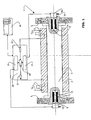
- Figure 1 illustrates, in simplified and partial form, an elongate rotating structure 1 that defines a longitudinal axis and includes a shaft or spindle 3 and two grinding wheels 5 and 6, coupled to the ends of the shaft 3 and spaced out along the longitudinal axis.
- a grinding machine support 2 for example the wheel-carrier, defines an axis of rotation and supports the rotating structure 1 in such a way that the longitudinal axis substantially coincides with the axis of rotation, and the spindle 3, that is driven in a known way not shown in the figure, can rotate about said axis.
- Two vibration-detecting sensors 7 and 8 are fixed to the stationary support 2 near transversal checking sections S 1 and S 2 , near the ends of shaft 3.
- Balancing devices 9 and 10 are housed, for example, in suitable recesses at the ends of the spindle 3 near the transversal sections S 1 and S 2 and each includes a pair of eccentric balancing masses - shown in simplified form and indentified by reference number 11, 13 and 12, 14, respectively - angularly movable about the longitudinal axis by means of associated motors, not shown in the figure.
- Transmission units 15 and 16 transmit the power supply for the motors and the information relating to the required angular displacements of the masses to the balancing devices 9 and 10, by means of contactless couplings for example of the inductive type - per se known and not shown in the figure.
- Processing and control means 20 are connected to the machine logic 40.
- Figure 1 shows, in simplified form, some circuits and units of the processing and control means 20, and more specifically filtering and detection circuits 21 and 22 connected to the vibration-detecting sensors 7 and 8, respectively, two processing and control units 23 and 24 connected to the balancing devices 9 and 10, respectively, and combining circuits 25.
- the outputs of each of the filtering and detection circuits 21 and 22 are connected to the combining circuits 25, in turn connected to both the processing units 23 and 24.
- a balancing cycle has to be carried out, for example, as a consequence of the substitution, or the dressing, of the grinding wheels 5 and/or 6.
- the decision as to whether carry out the balancing cycle is taken by an operator, or, in the example shown in figure 1 , by the machine logic 40 that controls the start (block 30) of this cycle.
- the sensors 7 and 8 detect the vibrations at sections S 1 and S 2 , respectively, and send associated signals to the processing and control means 20. More specifically, the signals of the sensors 7 and 8 are sent to the circuits 21 and 22, respectively, where, according to a known process (blocks 31 and 32), they are filtered and detected for obtaining, for example, direct voltages V 01 and V 02 indicative of the modules of the two detected vibrations.
- the signals output from circuits 21 and 22 are sent to combining circuits 25 (block 33), that in turn send to both units 23 and 24 a combined signal V C that is indicative of a combination of the modules of the vibrations detected by sensors 7 and 8.
- V T a pre-determined threshold value
- the units 23 and 24 control, by means of their associated transmission units 15 and 16, displacements of the masses 11, 13 and 12, 14 of the balancing devices 9 and 10 (blocks 35 and 36).
- the operation of the balancing devices 9 and 10 is controlled by the associated units 23 and 24, that control displacements of the masses 11, 13 and 12, 14 till the value of the combined signal V C - that varies as the vibrations vary at sections S 1 and S 2 as a consequence of the various positions taken by the masses 11-14 - reaches or becomes lower than the threshold value V T .
- each of the units 23 and 24 controls, in a simultaneous and independent way with respect to the other, displacements of the masses of the associated balancing devices 9 and 10, both with the aim of minimizing the value of the combined signal V C .
- Another embodiment of the present invention foresees a method according to which the displacements of the masses 11, 13 and 12, 14, respectively, are controlled in an alternative and sequential way by their associated units 23 and 24, till the value of the same combined signal V C reaches the threshold value V T .
- Figure 3b is a graph representing a possible trend in time of the modules V 01 and V 02 of the vibrations detected by sensors 7 and 8, and of the combined signal V C (in this case the sum of the modules V 01 and V 02 ) in a typical balancing cycle according to the method disclosed in the present invention in an application as the one shown in figure 1 .
- FIG 3a shows, instead, the possible trend of the same values of the modules of the vibrations at the sections S 1 and S 2 (identified as V 01 ' and V 02 ' ) in an identical application, in which the applied method is substantially similar to the one described in the patent application DE-A-2345664 , in other words each balancing device 9 ( 10 ) is controlled by its associated processing and control unit 23 (24) in a sequential way and on the basis of the signal of just sensor 7 (8) applied at the associated section S 1 ( S 2 ).
- the shape of the graph of figure 3a shows how, while the value of signal V 01 ' of a first vibration-detecting sensor decreases to a minimum, thanks to the action of its associated balancing device in time t1, the value of the signal V 02 ' of the second sensor is simultaneously changed and in general increases. In a symmetric way the subsequent actuation of the other balancing device makes the vibrations detected by the second sensor (V 02 ') decrease, but causes increasing of the value of the first signal (V 01 ') increase in the time interval from t1 to t2 .
- the graph of figure 3b shows how, instead, by applying a method according to the present invention, the balancing action of both the devices 9 and 10 that tend to minimize the value of the combined signal V C leads to a convergence of the signals V 01 and V 02 of the individual sensors 7 and 8 towards the minimum requested value.
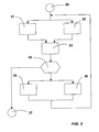
- V C1 and V C2 are compared with respective threshold values V T1 and V T2 (block 56) and when V C ⁇ 1 ⁇ V T ⁇ 1 AND V C ⁇ 2 ⁇ V T ⁇ 2 the balancing cycle ends (block 61).
- each balancing device e.g. 9 is controlled (block 57) in a known way until (block 59) a minimum value of the relevant combined signal V C1 is reached, and then - if the balancing procedure needs to go on (blocks 55) - the other balancing device 10 is similarly controlled (blocks 58 and 60).
- Block 56 represents a test for establishing which of the two balancing devices 9, 10 must be controlled in the above-mentioned sequence.
- the combinations V C1 and V C2 are both achieved on the basis of both the signals provided by the vibration-detecting sensors 7 and 8.
- the described methods and apparatus enable to achieve the required dynamic balancing in two planes or sections in a simple and efficient way, and can be applied to elongate rotating structures of various types, including, for example, two grinding wheels coupled to an identical spindle (as shown in the example in figure 1 ), or a single elongate grinding wheel (as the one, for centerless grinding machines, shown in the previously mentioned patent application DE-A-2345664 ), or a single grinding wheel coupled near an end of a rotating spindle, or rotating tools of other shapes and arrangements.
- the processing and control means 20 can be achieved in a different way with respect to what is shown in simplified form in figure 1 .
- the filtering and the detection of the signals of the sensors 7 and 8 can be carried out by circuits included in the processing and control units 23 and 24 and the latter can be mutually connected for each achieving the combination of the two obtained signals, without the need of the combining circuits 25.
- the balancing devices - one or both - can have different shape and structure with respect to those (9 and 10) shown in figure 1 , and can be, for example, coupled externally to their associated grinding wheel 5 and/or 6 instead of at the interior of the spindle 3, or include masses translating in transversal directions instead of rotating, or have other per se known characteristics.
Landscapes
- Physics & Mathematics (AREA)
- General Physics & Mathematics (AREA)
- Testing Of Balance (AREA)
- Constituent Portions Of Griding Lathes, Driving, Sensing And Control (AREA)
- Manufacture Of Motors, Generators (AREA)
- Analysing Materials By The Use Of Radiation (AREA)
- Pressure Welding/Diffusion-Bonding (AREA)
- Turbine Rotor Nozzle Sealing (AREA)
Claims (13)
- Verfahren zur dynamischen Auswuchtung einer drehbaren Struktur (1), die sich um eine Längsachse dreht, mit Hilfe von einer Vorrichtung, die zwei Sensoren (7,8) zum Nachweis von Schwingungen, zwei entsprechenden Auswuchtvorrichtungen (9,10), und Verarbeitungs- und Steuereinrichtungen (20), die die von den zwei Sensoren (7,8) zum Nachweis von Schwingungen angegebene Signale verarbeiten und die Auswuchtvorrichtungen (9,10) steuern können, umfasst, wobei das Verfahren die folgenden Schritte umfasst:- Anordnung jedes Sensors zum Nachweis von Schwingungen und seiner entsprechenden Auswuchtvorrichtung bei einem Prüfabschnitt, wobei die zwei Prüfabschnitte (S1, S2) entlang der Längsachse entfernt sind, und- Steuerung der Arbeitsweise der Auswuchtvorrichtungen (9,10) auf der Basis der Signale (V01, V02) der zwei Sensoren (7,8) zum Nachweis von Schwingungen,dadurch gekennzeichnet dass die Signale (V01, V02) der zwei Sensoren (7,8) zum Nachweis von Schwingungen zum Erreichen eines oder mehrerer kombinierten Signale (VC; VC1, VC2) zusammen (33;53,54) verarbeitet werden, und die Arbeitsweise (35,36;57,58) der zwei Auswuchtvorrichtungen (9,10) auf der Basis von Werte des einen oder der mehreren kombinierten Signale (VC; VC1, VC2) gesteuert (34;55,59,60) wird.
- Verfahren nach Anspruch 1, bei dem die Arbeitsweise (35,36) der zwei Auswuchtvorrichtungen (9,10) gleichzeitig und selbständig relativ zueinander gesteuert wird.
- Verfahren nach Anspruch 1, bei dem die Arbeitsweise (57,58) der zwei Auswuchtvorrichtungen (9,10) sequentiell relativ zueinander gesteuert wird.
- Verfahren nach einem der vorangehenden Ansprüche, bei dem die Signale (V01, V02) der zwei Sensoren (7,8) zum Nachweis von Schwingungen zusammen (3) verarbeitet werden, um nur ein (VC) des einen oder der mehreren kombinierten Signale (VC; VC1, VC2) zu erreichen, und die Arbeitsweise (35,36) von beiden der zwei Auswuchtvorrichtungen (9,10) auf der Basis von Werte des nur einen kombinierten Signals (VC) gesteuert (34) wird.
- Verfahren nach einem der vorangehenden Ansprüche, bei dem die Signale der zwei Sensoren (7,8) zum Nachweis von Schwingungen verarbeitet (33;53,54) werden, um das ein oder die mehreren kombinierten Signale (VC; VC1, VC2) als eine oder mehrere Kombinationen der Moduln (V01, V02) der Schwingungen der zwei Prüfabschnitte (S1, S2) anzeigenden Signale zu erreichen.
- Verfahren nach Anspruch 5, bei dem mindestens ein (VC) des einen oder der mehreren Signale (VC; VC1, VC2) als die Summe der Moduln (V01, V02) erreicht wird.
- Verfahren nach Anspruch 5, bei dem mindestens ein (VC) des einen oder der mehreren kombinierten Signale (VC; VC1, VC2) als Quadratwurzel der Summe der Quadrate der Moduln (V01, V02) erreicht wird.
- Verfahren nach Anspruch 5, bei dem ein oder mehrere kombinierten Signale (VC; VC1, VC2) als eine oder mehrere linearen Kombinationen der Moduln (V01, V02) erreicht werden.
- Einrichtung zur dynamischen Auswuchtung einer drehbaren Struktur (1) die sich um eine Längsachse dreht, mit Hilfe von einem Verfahren nach Anspruch 1, bei der die Verarbeitungs- und Steuereinrichtungen (20) zwei Verarbeitungs- und Steuerungseinheiten (23,24) umfassen, wobei jede Verarbeitungs- und Steuerungseinheit zur Steuerung einer der Auswuchtvorrichtungen (9,10) dient.
- Einrichtung nach Anspruch 9, bei der jede der Auswuchtvorrichtungen unter der Steuerung der entsprechenden Verarbeitungs- und Steuerungseinheiten (23,24) bewegliche Wuchtmassen (111,13;12,14) umfasst.
- Einrichtung nach Anspruch 10, bei der jede der Auswuchtvorrichtungen (9,10) ein Paar der Wuchtmassen (11,13;12,14) umfasst, wobei die Massen relativ zur Längsachse exzentrisch und um die Längsachse winkelbeweglich sind.
- Einrichtung nach einem der Ansprüche von 9 bis 11, die Filter- und Detektorschaltungen (21,22) umfasst, die zum Empfang der von den Sensoren (7,8) zum Nachweis von Schwingungen gesendeten Signale und zur Bereitstellung der den Verlauf der entsprechenden Moduln anzeigenden Signale (V01, V02) dienen.
- Einrichtung nach einem der Ansprüche von 9 bis 12, zur dynamischen Auswuchtung einer drehbaren Struktur (1) einer Werkzeugmaschine, die eine Spindel (3) und zwei an entfernten Positionen entlang der Längsachse mit der Spindel verbundene Schleifscheiben (5,6) umfasst, wobei die Auswuchtvorrichtungen (9,10) mit den Schleifscheiben (5,6) verbunden sind und mit den Schleifscheiben drehbar sind.
Applications Claiming Priority (3)
| Application Number | Priority Date | Filing Date | Title |
|---|---|---|---|
| IT2001BO000560A ITBO20010560A1 (it) | 2001-09-17 | 2001-09-17 | Metodo e apparecchiatura per l'equilibratura dinamica di una struttura rotante |
| ITBO20010056 | 2001-09-17 | ||
| PCT/EP2002/010282 WO2003025535A1 (en) | 2001-09-17 | 2002-09-13 | Method and apparatus for the dynamic balancing of a rotating structure |
Publications (3)
| Publication Number | Publication Date |
|---|---|
| EP1428005A1 EP1428005A1 (de) | 2004-06-16 |
| EP1428005B1 true EP1428005B1 (de) | 2010-11-24 |
| EP1428005B2 EP1428005B2 (de) | 2013-11-20 |
Family
ID=11439605
Family Applications (1)
| Application Number | Title | Priority Date | Filing Date |
|---|---|---|---|
| EP02779347.0A Expired - Lifetime EP1428005B2 (de) | 2001-09-17 | 2002-09-13 | Methode und einrichtung zur dynamischen auswuchtung einer rotierenden struktur |
Country Status (8)
| Country | Link |
|---|---|
| US (1) | US6879882B2 (de) |
| EP (1) | EP1428005B2 (de) |
| JP (1) | JP3987035B2 (de) |
| AT (1) | ATE489610T1 (de) |
| DE (1) | DE60238420D1 (de) |
| ES (1) | ES2353375T5 (de) |
| IT (1) | ITBO20010560A1 (de) |
| WO (1) | WO2003025535A1 (de) |
Families Citing this family (13)
| Publication number | Priority date | Publication date | Assignee | Title |
|---|---|---|---|---|
| US20060226696A1 (en) * | 2005-03-30 | 2006-10-12 | Jones Gordon B | Self-balancing wheel |
| US7270007B2 (en) * | 2005-06-03 | 2007-09-18 | Serrano Norman S | Apparatus and method for reducing vibration |
| DE102005062470A1 (de) * | 2005-12-27 | 2007-07-12 | BSH Bosch und Siemens Hausgeräte GmbH | Vorrichtung und Verfahren zum Dämpfen der Unwucht eines rotierenden Teils und Geschirrspülmaschine mit einer derartigen Vorrichtung |
| JP5433151B2 (ja) * | 2008-01-08 | 2014-03-05 | 株式会社東芝 | 回転機械の調整装置、回転機械の調整方法及びx線ct装置の製造方法 |
| US8359921B2 (en) * | 2010-09-13 | 2013-01-29 | GM Global Technology Operations LLC | Dynamic balancing of vehicle wheel assemblies |
| CN102095555B (zh) * | 2010-12-07 | 2012-03-28 | 西安交通大学 | 高速电主轴在线自动平衡实验系统 |
| CN102332796A (zh) * | 2011-06-24 | 2012-01-25 | 东方电气(乐山)新能源设备有限公司 | 1.5mw风力发电机带径向风扇转子动平衡校正方法 |
| ES2798101T3 (es) * | 2012-10-02 | 2020-12-09 | Balance Systems Srl | Procedimiento y dispositivo de balanceo para un cuerpo rotatorio |
| CN108958299A (zh) * | 2018-07-12 | 2018-12-07 | 西安交通大学 | 一种实时调整转子中心高度的智能支撑装置及方法 |
| CN110888464B (zh) * | 2019-11-12 | 2021-06-04 | 上海交通大学 | 变转速螺旋桨轴系纵向和横向多模态振动控制装置及方法 |
| CN110861762B (zh) * | 2019-11-12 | 2021-08-03 | 上海交通大学 | 轴系振动控制的自适应压电分流半被动控制装置及方法 |
| CN112217362B (zh) * | 2020-09-25 | 2023-04-21 | 哈尔滨东北泵业有限责任公司 | 一种可自动校正转子不平衡的离心泵及其校正方法 |
| CN113203522B (zh) * | 2021-05-07 | 2022-08-09 | 中国航空工业集团公司北京长城计量测试技术研究所 | 一种旋转机械动平衡控制系统及方法 |
Citations (1)
| Publication number | Priority date | Publication date | Assignee | Title |
|---|---|---|---|---|
| DE2345664A1 (de) * | 1973-09-11 | 1975-07-24 | Szerszamgepipari Muevek | Auswuchtvorrichtung mit zwei oder mehreren auswuchtebenen zum dynamischen auswuchten von maschinenteilen, insbesondere breiten schleifkoerpern waehrend ihres umlaufes |
Family Cites Families (18)
| Publication number | Priority date | Publication date | Assignee | Title |
|---|---|---|---|---|
| JPS4946029B1 (de) * | 1970-06-30 | 1974-12-07 | ||
| DE2134270B2 (de) | 1971-07-09 | 1973-10-04 | Werkzeugmaschinenfabrik Adolf Waldrich Coburg, 8630 Coburg | Vorrichtung zum statischen und dynamischen Auswuchten von Schleif scheiben an Schleifmaschinen wahrend des Umlaufs |
| IT1052844B (it) * | 1975-12-16 | 1981-07-20 | Cnen | Procedimento ed apparecchio per l l equilibratura dinamica di corpi in rotazione in particolare per centrifughe |
| DE2737524C2 (de) † | 1977-08-19 | 1983-01-27 | Gebr. Hofmann Gmbh & Co Kg Maschinenfabrik, 6100 Darmstadt | Vorrichtung zum Auswuchten von genormten Rotoren, insbesondere von Kraftfahrzeugrädern |
| DE2740454A1 (de) † | 1977-09-08 | 1979-03-15 | Hofmann Gmbh & Co Kg Maschinen | Verfahren und vorrichtung zum auswuchten von rotoren, insbesondere von kfz-raedern |
| DE2756829A1 (de) † | 1977-12-20 | 1979-06-21 | Hofmann Gmbh & Co Kg Maschinen | Schaltungsanordnung zur ermittlung der ausgleichsgewichtsgroessen und -phasenlagen fuer rotierende maschinenteile, insbesondere bei der betriebsauswuchtung |
| DE2934161A1 (de) | 1979-08-23 | 1981-03-26 | Životov, Jurij Grigor'evič, Dnepropetrovsk | Verfahren zum auswuchten von rotationskoerpern und einrichtung zur ausfuehrung desselben |
| IT1146185B (it) * | 1980-08-08 | 1986-11-12 | Cnen | Procedimento ed apparecchio per l'equilibratura dinamica di corpiruotanti |
| FR2506455A1 (fr) * | 1981-05-21 | 1982-11-26 | Elf Aquitaine | Systeme d'analyse des mouvements vibratoires d'une machine tournante |
| US4653324A (en) * | 1985-08-15 | 1987-03-31 | Rockwell International Corporation | Dynamic balancing machine |
| DD261838A1 (de) † | 1987-07-02 | 1988-11-09 | Werkzeugmasch Heckert Veb | Schaltungsanordnung zur steuerung eines auswuchtvorganges in zwei ebenen |
| DE3726024A1 (de) * | 1987-08-05 | 1989-02-16 | Hofmann Werkstatt Technik | Vorrichtung zum umwuchtausgleich in zwei ebenen an einem rotor, insbesondere kraftfahrzeugrad |
| US4868762A (en) * | 1987-09-14 | 1989-09-19 | Balance Technology, Inc. | Automatic digital dynamic balancing machine and method |
| DE4122816C2 (de) † | 1991-07-10 | 1997-09-11 | Hofmann Maschinenbau Gmbh | Verfahren zur Unwuchtmessung für einen in zwei Ausgleichsebenen an einem Rotor durchzuführenden Unwuchtausgleich und Vorrichtung zur Durchführung des Verfahrens |
| DE4240787C2 (de) † | 1992-12-04 | 1997-09-11 | Hofmann Maschinenbau Gmbh | Verfahren und Vorrichtung zum dynamischen Auswuchten eines Rotors |
| IT1263065B (it) * | 1993-03-22 | 1996-07-24 | Marposs Spa | Apparecchio per l'equilibratura dinamica di un corpo rotante. |
| GB9523651D0 (en) * | 1995-11-18 | 1996-01-17 | Gkn Westland Helicopters Ltd | Helicopter and method for reucing vibration of a helicopter fuselage |
| US5992232A (en) * | 1996-05-22 | 1999-11-30 | Asahi Kogaku Kogyo Kabushiki Kaisha | Dynamic balance adjusting apparatus |
-
2001
- 2001-09-17 IT IT2001BO000560A patent/ITBO20010560A1/it unknown
-
2002
- 2002-09-13 US US10/488,757 patent/US6879882B2/en not_active Expired - Fee Related
- 2002-09-13 AT AT02779347T patent/ATE489610T1/de not_active IP Right Cessation
- 2002-09-13 EP EP02779347.0A patent/EP1428005B2/de not_active Expired - Lifetime
- 2002-09-13 DE DE60238420T patent/DE60238420D1/de not_active Expired - Lifetime
- 2002-09-13 WO PCT/EP2002/010282 patent/WO2003025535A1/en not_active Ceased
- 2002-09-13 ES ES02779347.0T patent/ES2353375T5/es not_active Expired - Lifetime
- 2002-09-13 JP JP2003529115A patent/JP3987035B2/ja not_active Expired - Fee Related
Patent Citations (1)
| Publication number | Priority date | Publication date | Assignee | Title |
|---|---|---|---|---|
| DE2345664A1 (de) * | 1973-09-11 | 1975-07-24 | Szerszamgepipari Muevek | Auswuchtvorrichtung mit zwei oder mehreren auswuchtebenen zum dynamischen auswuchten von maschinenteilen, insbesondere breiten schleifkoerpern waehrend ihres umlaufes |
Also Published As
| Publication number | Publication date |
|---|---|
| ITBO20010560A1 (it) | 2003-03-17 |
| DE60238420D1 (de) | 2011-01-05 |
| EP1428005B2 (de) | 2013-11-20 |
| EP1428005A1 (de) | 2004-06-16 |
| WO2003025535A1 (en) | 2003-03-27 |
| US20040243283A1 (en) | 2004-12-02 |
| JP3987035B2 (ja) | 2007-10-03 |
| ES2353375T5 (es) | 2014-02-19 |
| JP2005503554A (ja) | 2005-02-03 |
| US6879882B2 (en) | 2005-04-12 |
| ITBO20010560A0 (it) | 2001-09-17 |
| ES2353375T3 (es) | 2011-03-01 |
| ATE489610T1 (de) | 2010-12-15 |
Similar Documents
| Publication | Publication Date | Title |
|---|---|---|
| EP1428005B1 (de) | Methode und einrichtung zur dynamischen auswuchtung einer rotierenden struktur | |
| JP3285870B2 (ja) | 回転体の動的平衡化装置 | |
| US11344985B2 (en) | Machine tool, in particular for drilling | |
| KR102224700B1 (ko) | 밸런싱 장치를 포함하는 가공 헤드 | |
| CN101918175B (zh) | 用于同时研磨曲轴的多个轴承以及端面的研磨中心和方法 | |
| KR20160133494A (ko) | 대형 크랭크 샤프트를 연삭하는 방법 및 장치 | |
| US8950507B2 (en) | Device for preventing vibrations in a tool spindle | |
| US7461439B2 (en) | Method for detecting malfunction in clamping and machine tool | |
| EP1404486B1 (de) | Verfahren und vorrichtung zur prüfung des bearbeitungsverfahrens einer werkzeugmaschine | |
| JP2013508176A (ja) | 研削及びバリ取り用研削盤と、研削及びバリ取りの方法 | |
| CN202291683U (zh) | 工作机械 | |
| US6595052B2 (en) | Self-calibrating machines for balancing work pieces and methods of machine calibration | |
| US20220126384A1 (en) | Method for grinding or polishing a gearwheel or a workpiece with a gearwheel-like profile in a grinding or polishing machine | |
| CN110849624A (zh) | 一种主轴径向加载装置及机床主轴性能测试方法 | |
| US20040059459A1 (en) | Processing machine | |
| EP1764187A2 (de) | Verfahren zum Bearbeiten einer Fläche und gleichzeitigen Messen von Parametern der Fläche | |
| WO2003100374A1 (en) | System and method for balancing a rotating structure | |
| CN116669887A (zh) | 具有平衡装置和夹紧元件的刀具头以及具有这种刀具头的机床 | |
| JPH08300244A (ja) | バランサー機構付旋盤 | |
| JP4730944B2 (ja) | 多頭研削盤及び多頭研削盤を用いた研削方法 | |
| US6520012B1 (en) | Process and device for unbalance correction | |
| KR102864295B1 (ko) | 회전체 공작물의 언밸런싱 보정 장치 및 방법 | |
| GB1595510A (en) | Dynamic balancing machine | |
| JP4065185B2 (ja) | 非円形回転体ワークの研削方法及びその装置 | |
| KR20220070091A (ko) | 수소연료전지 자동차의 고속 회전체용 자동 밸런싱장비 |
Legal Events
| Date | Code | Title | Description |
|---|---|---|---|
| PUAI | Public reference made under article 153(3) epc to a published international application that has entered the european phase |
Free format text: ORIGINAL CODE: 0009012 |
|
| 17P | Request for examination filed |
Effective date: 20040405 |
|
| AK | Designated contracting states |
Kind code of ref document: A1 Designated state(s): AT BE BG CH CY CZ DE DK EE ES FI FR GB GR IE IT LI LU MC NL PT SE SK TR |
|
| AX | Request for extension of the european patent |
Extension state: AL LT LV MK RO SI |
|
| RAP1 | Party data changed (applicant data changed or rights of an application transferred) |
Owner name: MARPOSS SOCIETA' PER AZIONI |
|
| GRAP | Despatch of communication of intention to grant a patent |
Free format text: ORIGINAL CODE: EPIDOSNIGR1 |
|
| GRAS | Grant fee paid |
Free format text: ORIGINAL CODE: EPIDOSNIGR3 |
|
| GRAA | (expected) grant |
Free format text: ORIGINAL CODE: 0009210 |
|
| AK | Designated contracting states |
Kind code of ref document: B1 Designated state(s): AT BE BG CH CY CZ DE DK EE ES FI FR GB GR IE IT LI LU MC NL PT SE SK TR |
|
| REG | Reference to a national code |
Ref country code: GB Ref legal event code: FG4D |
|
| REG | Reference to a national code |
Ref country code: CH Ref legal event code: EP |
|
| REG | Reference to a national code |
Ref country code: IE Ref legal event code: FG4D |
|
| REF | Corresponds to: |
Ref document number: 60238420 Country of ref document: DE Date of ref document: 20110105 Kind code of ref document: P |
|
| REG | Reference to a national code |
Ref country code: ES Ref legal event code: FG2A Effective date: 20110217 |
|
| REG | Reference to a national code |
Ref country code: NL Ref legal event code: VDEP Effective date: 20101124 |
|
| PG25 | Lapsed in a contracting state [announced via postgrant information from national office to epo] |
Ref country code: SE Free format text: LAPSE BECAUSE OF FAILURE TO SUBMIT A TRANSLATION OF THE DESCRIPTION OR TO PAY THE FEE WITHIN THE PRESCRIBED TIME-LIMIT Effective date: 20101124 Ref country code: PT Free format text: LAPSE BECAUSE OF FAILURE TO SUBMIT A TRANSLATION OF THE DESCRIPTION OR TO PAY THE FEE WITHIN THE PRESCRIBED TIME-LIMIT Effective date: 20110324 Ref country code: FI Free format text: LAPSE BECAUSE OF FAILURE TO SUBMIT A TRANSLATION OF THE DESCRIPTION OR TO PAY THE FEE WITHIN THE PRESCRIBED TIME-LIMIT Effective date: 20101124 Ref country code: BG Free format text: LAPSE BECAUSE OF FAILURE TO SUBMIT A TRANSLATION OF THE DESCRIPTION OR TO PAY THE FEE WITHIN THE PRESCRIBED TIME-LIMIT Effective date: 20110224 Ref country code: NL Free format text: LAPSE BECAUSE OF FAILURE TO SUBMIT A TRANSLATION OF THE DESCRIPTION OR TO PAY THE FEE WITHIN THE PRESCRIBED TIME-LIMIT Effective date: 20101124 Ref country code: AT Free format text: LAPSE BECAUSE OF FAILURE TO SUBMIT A TRANSLATION OF THE DESCRIPTION OR TO PAY THE FEE WITHIN THE PRESCRIBED TIME-LIMIT Effective date: 20101124 Ref country code: CY Free format text: LAPSE BECAUSE OF FAILURE TO SUBMIT A TRANSLATION OF THE DESCRIPTION OR TO PAY THE FEE WITHIN THE PRESCRIBED TIME-LIMIT Effective date: 20101124 |
|
| PG25 | Lapsed in a contracting state [announced via postgrant information from national office to epo] |
Ref country code: GR Free format text: LAPSE BECAUSE OF FAILURE TO SUBMIT A TRANSLATION OF THE DESCRIPTION OR TO PAY THE FEE WITHIN THE PRESCRIBED TIME-LIMIT Effective date: 20110225 |
|
| PG25 | Lapsed in a contracting state [announced via postgrant information from national office to epo] |
Ref country code: EE Free format text: LAPSE BECAUSE OF FAILURE TO SUBMIT A TRANSLATION OF THE DESCRIPTION OR TO PAY THE FEE WITHIN THE PRESCRIBED TIME-LIMIT Effective date: 20101124 Ref country code: CZ Free format text: LAPSE BECAUSE OF FAILURE TO SUBMIT A TRANSLATION OF THE DESCRIPTION OR TO PAY THE FEE WITHIN THE PRESCRIBED TIME-LIMIT Effective date: 20101124 Ref country code: BE Free format text: LAPSE BECAUSE OF FAILURE TO SUBMIT A TRANSLATION OF THE DESCRIPTION OR TO PAY THE FEE WITHIN THE PRESCRIBED TIME-LIMIT Effective date: 20101124 |
|
| PG25 | Lapsed in a contracting state [announced via postgrant information from national office to epo] |
Ref country code: DK Free format text: LAPSE BECAUSE OF FAILURE TO SUBMIT A TRANSLATION OF THE DESCRIPTION OR TO PAY THE FEE WITHIN THE PRESCRIBED TIME-LIMIT Effective date: 20101124 Ref country code: SK Free format text: LAPSE BECAUSE OF FAILURE TO SUBMIT A TRANSLATION OF THE DESCRIPTION OR TO PAY THE FEE WITHIN THE PRESCRIBED TIME-LIMIT Effective date: 20101124 |
|
| PLBI | Opposition filed |
Free format text: ORIGINAL CODE: 0009260 |
|
| PLAX | Notice of opposition and request to file observation + time limit sent |
Free format text: ORIGINAL CODE: EPIDOSNOBS2 |
|
| 26 | Opposition filed |
Opponent name: FIRMA DITTEL MESSTECHNIK GMBH Effective date: 20110824 |
|
| REG | Reference to a national code |
Ref country code: DE Ref legal event code: R026 Ref document number: 60238420 Country of ref document: DE Effective date: 20110824 |
|
| PLAF | Information modified related to communication of a notice of opposition and request to file observations + time limit |
Free format text: ORIGINAL CODE: EPIDOSCOBS2 |
|
| PLBB | Reply of patent proprietor to notice(s) of opposition received |
Free format text: ORIGINAL CODE: EPIDOSNOBS3 |
|
| PG25 | Lapsed in a contracting state [announced via postgrant information from national office to epo] |
Ref country code: MC Free format text: LAPSE BECAUSE OF NON-PAYMENT OF DUE FEES Effective date: 20110930 |
|
| REG | Reference to a national code |
Ref country code: IE Ref legal event code: MM4A |
|
| REG | Reference to a national code |
Ref country code: FR Ref legal event code: ST Effective date: 20120531 |
|
| PG25 | Lapsed in a contracting state [announced via postgrant information from national office to epo] |
Ref country code: IE Free format text: LAPSE BECAUSE OF NON-PAYMENT OF DUE FEES Effective date: 20110913 |
|
| PLBP | Opposition withdrawn |
Free format text: ORIGINAL CODE: 0009264 |
|
| PG25 | Lapsed in a contracting state [announced via postgrant information from national office to epo] |
Ref country code: FR Free format text: LAPSE BECAUSE OF NON-PAYMENT OF DUE FEES Effective date: 20110930 |
|
| PG25 | Lapsed in a contracting state [announced via postgrant information from national office to epo] |
Ref country code: LU Free format text: LAPSE BECAUSE OF NON-PAYMENT OF DUE FEES Effective date: 20110913 |
|
| PG25 | Lapsed in a contracting state [announced via postgrant information from national office to epo] |
Ref country code: TR Free format text: LAPSE BECAUSE OF FAILURE TO SUBMIT A TRANSLATION OF THE DESCRIPTION OR TO PAY THE FEE WITHIN THE PRESCRIBED TIME-LIMIT Effective date: 20101124 |
|
| PUAH | Patent maintained in amended form |
Free format text: ORIGINAL CODE: 0009272 |
|
| STAA | Information on the status of an ep patent application or granted ep patent |
Free format text: STATUS: PATENT MAINTAINED AS AMENDED |
|
| 27A | Patent maintained in amended form |
Effective date: 20131120 |
|
| AK | Designated contracting states |
Kind code of ref document: B2 Designated state(s): AT BE BG CH CY CZ DE DK EE ES FI FR GB GR IE IT LI LU MC NL PT SE SK TR |
|
| REG | Reference to a national code |
Ref country code: CH Ref legal event code: AELC |
|
| REG | Reference to a national code |
Ref country code: DE Ref legal event code: R102 Ref document number: 60238420 Country of ref document: DE Effective date: 20131120 |
|
| REG | Reference to a national code |
Ref country code: ES Ref legal event code: DC2A Ref document number: 2353375 Country of ref document: ES Kind code of ref document: T5 Effective date: 20140219 |
|
| PGFP | Annual fee paid to national office [announced via postgrant information from national office to epo] |
Ref country code: GB Payment date: 20150924 Year of fee payment: 14 Ref country code: ES Payment date: 20150924 Year of fee payment: 14 Ref country code: CH Payment date: 20150924 Year of fee payment: 14 |
|
| PGFP | Annual fee paid to national office [announced via postgrant information from national office to epo] |
Ref country code: DE Payment date: 20151001 Year of fee payment: 14 Ref country code: IT Payment date: 20150930 Year of fee payment: 14 |
|
| REG | Reference to a national code |
Ref country code: DE Ref legal event code: R119 Ref document number: 60238420 Country of ref document: DE |
|
| REG | Reference to a national code |
Ref country code: CH Ref legal event code: PL |
|
| GBPC | Gb: european patent ceased through non-payment of renewal fee |
Effective date: 20160913 |
|
| PG25 | Lapsed in a contracting state [announced via postgrant information from national office to epo] |
Ref country code: LI Free format text: LAPSE BECAUSE OF NON-PAYMENT OF DUE FEES Effective date: 20160930 Ref country code: DE Free format text: LAPSE BECAUSE OF NON-PAYMENT OF DUE FEES Effective date: 20170401 Ref country code: GB Free format text: LAPSE BECAUSE OF NON-PAYMENT OF DUE FEES Effective date: 20160913 Ref country code: CH Free format text: LAPSE BECAUSE OF NON-PAYMENT OF DUE FEES Effective date: 20160930 |
|
| PG25 | Lapsed in a contracting state [announced via postgrant information from national office to epo] |
Ref country code: IT Free format text: LAPSE BECAUSE OF NON-PAYMENT OF DUE FEES Effective date: 20160913 |
|
| PG25 | Lapsed in a contracting state [announced via postgrant information from national office to epo] |
Ref country code: ES Free format text: LAPSE BECAUSE OF NON-PAYMENT OF DUE FEES Effective date: 20160914 |
|
| REG | Reference to a national code |
Ref country code: ES Ref legal event code: FD2A Effective date: 20181126 |