EP1428085B1 - Indicateur visuel de module entree/sortie d'unite de commande et dispositif de securite - Google Patents
Indicateur visuel de module entree/sortie d'unite de commande et dispositif de securite Download PDFInfo
- Publication number
- EP1428085B1 EP1428085B1 EP02757326A EP02757326A EP1428085B1 EP 1428085 B1 EP1428085 B1 EP 1428085B1 EP 02757326 A EP02757326 A EP 02757326A EP 02757326 A EP02757326 A EP 02757326A EP 1428085 B1 EP1428085 B1 EP 1428085B1
- Authority
- EP
- European Patent Office
- Prior art keywords
- light
- circuit
- terminal block
- block assembly
- adjacent
- Prior art date
- Legal status (The legal status is an assumption and is not a legal conclusion. Google has not performed a legal analysis and makes no representation as to the accuracy of the status listed.)
- Expired - Lifetime
Links
Images



Classifications
-
- G—PHYSICS
- G05—CONTROLLING; REGULATING
- G05B—CONTROL OR REGULATING SYSTEMS IN GENERAL; FUNCTIONAL ELEMENTS OF SUCH SYSTEMS; MONITORING OR TESTING ARRANGEMENTS FOR SUCH SYSTEMS OR ELEMENTS
- G05B19/00—Program-control systems
- G05B19/02—Program-control systems electric
- G05B19/04—Program control other than numerical control, i.e. in sequence controllers or logic controllers
- G05B19/05—Programmable logic controllers, e.g. simulating logic interconnections of signals according to ladder diagrams or function charts
- G05B19/054—Input/output
Definitions
- Systems and methods in accordance with various aspects of the present invention provide a controller input/output module visual indicator and safety means.
- the present invention may be described herein in terms of functional block components and various processing steps. It should be appreciated that such functional blocks may be realized by any number of hardware, firmware, and/or software components configured to perform the specified functions.
- the present invention may employ various circuitry and software means such as microprocessors, microcontrollers, integrated circuit components, memory elements, digital signal processing elements, look-up tables, databases, and the like, which may carry out a variety of functions under the control of one or more microprocessors or other control devices
- Such general techniques and components that are known to those skilled in the art are not described in detail herein.
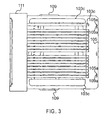
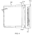
- light redirector 103 may further be configured to provide electrical shock protection from any electrical signals from circuitry mean 105.
- light redirector may further include one or more protrusions 103c configured to further cover those portions of the circuit 105 which may be electrically charged.
- each protrusion 103c thus is configured to protect the operator from electrical shock and prevent the circuit 105 from being disabled due to electrostatic discharge.
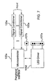
- FIG. 8 illustrates an exemplary input module functional block diagram of circuit 105.
- a customer's field wiring provides an input signal to the signal conditioner 105e of the input module.
- the signal conditioner 105e is configured to condition the input signal to set the proper operating characteristics of each input signal.
- the ON or OFF state of each signal conditioner 105e is detected by a microcontroller 105c or like processing means which in turn transmits this information to the LED driver to drive the LED 107a associated with each input signal.
- the microcontroller 105a also drives the status LED 107b to indicate the health or status of the input module as well as distributing the ON or OFF state of each input to the main controller via the peripheral interface and the controller backplane.
- the microcontroller uses the ON or OFF state of each input signal to implement the customer's control strategy.
Landscapes
- Physics & Mathematics (AREA)
- General Physics & Mathematics (AREA)
- Engineering & Computer Science (AREA)
- Automation & Control Theory (AREA)
- Illuminated Signs And Luminous Advertising (AREA)
- Circuit Arrangement For Electric Light Sources In General (AREA)
- Manipulator (AREA)
Claims (8)
- Appareil indicateur visuel de module de commande comprenant un ensemble bornier (111) ayant un canal (111b) formé à l'intérieur; un circuit (105) couplé à l'ensemble bornier (111) sur une première extrémité, le circuit (105) ayant au moins un émetteur de lumière (107b) sur lui situé à côté d'une seconde extrémité, chaque émetteur de lumière (107b) comprenant une diode électroluminescente ; et
un redirecteur de lumière (103) couplé au circuit (105) sur un premier côté du circuit (105), le redirecteur de lumière (103) ayant une extrémité proximale (103a) et une extrémité distale (103b), l'extrémité distale étant située à côté de l'ensemble bornier (111) pour être visionnée par un opérateur de tableau de commande et l'extrémité proximale (103a) étant située à côté de l'émetteur de lumière (107b), le canal étant configuré pour recevoir l'extrémité distale (103b), chaque redirecteur de lumière (103) étant configuré pour recevoir la lumière provenant de chaque émetteur de lumière (107b) correspondant sur l'extrémité proximale (103a) et pour transmettre la lumière à l'extrémité distale (103b), chaque redirecteur de lumière (103) étant en outre configuré pour avoir un coude de quatre-vingt-dix degrés avec des coupes de coin de quarante-cinq degrés situées à côté de chaque extrémité proximale (103a), l'émetteur de lumière n'étant pas situé à côté du câblage de champ du module. - Appareil selon la revendication 1, dans lequel l'émetteur de lumière est positionné suffisamment loin de l'ensemble bornier pour limiter le recouvrement des signaux à haute tension.
- Appareil selon la revendication 1, dans lequel l'émetteur de lumière est positionné à l'opposé de l'ensemble bornier.
- Appareil selon la revendication 1, le circuit (105) étant en communication avec un moyen de traitement et une interface d'opérateur, l'ensemble bornier (111) étant en communication avec le circuit (105) à l'aide d'un moyen de communication.
- Appareil selon l'une quelconque des revendications précédentes, chaque redirecteur de lumière (103) étant en outre configuré avec un coude de quatre-vingt-dix degrés approximativement avec des découpes de coin de quarante-cinq degrés approximativement situées à côté de chaque extrémité proximale (103a).
- Appareil selon la revendication 5, l'ensemble bornier (111) comprenant en outre une porte d'accès transparente (111a).
- Appareil selon la revendication 5, l'ensemble bornier (111) comprenant en outre un moyen de couplage amovible permettant de coupler l'ensemble au circuit (105).
- Appareil selon la revendication 1, chaque redirecteur de lumière (103) comprenant en outre au moins une saillie (103c) configurée pour couvrir des parties du circuit (105).
Applications Claiming Priority (3)
| Application Number | Priority Date | Filing Date | Title |
|---|---|---|---|
| US938955 | 2001-08-24 | ||
| US09/938,955 US6756911B2 (en) | 2001-08-24 | 2001-08-24 | Controller input/output module visual indicator and safety means |
| PCT/US2002/026814 WO2003019306A2 (fr) | 2001-08-24 | 2002-08-22 | Indicateur visuel de module entree/sortie d'unite de commande et dispositif de securite |
Publications (2)
| Publication Number | Publication Date |
|---|---|
| EP1428085A2 EP1428085A2 (fr) | 2004-06-16 |
| EP1428085B1 true EP1428085B1 (fr) | 2008-05-07 |
Family
ID=25472281
Family Applications (1)
| Application Number | Title | Priority Date | Filing Date |
|---|---|---|---|
| EP02757326A Expired - Lifetime EP1428085B1 (fr) | 2001-08-24 | 2002-08-22 | Indicateur visuel de module entree/sortie d'unite de commande et dispositif de securite |
Country Status (5)
| Country | Link |
|---|---|
| US (1) | US6756911B2 (fr) |
| EP (1) | EP1428085B1 (fr) |
| AU (1) | AU2002323349A1 (fr) |
| DE (1) | DE60226461D1 (fr) |
| WO (1) | WO2003019306A2 (fr) |
Families Citing this family (7)
| Publication number | Priority date | Publication date | Assignee | Title |
|---|---|---|---|---|
| US20100310733A1 (en) * | 2007-11-28 | 2010-12-09 | Steve Hoffman | Pressurized cooking oven |
| US8178802B2 (en) * | 2008-07-31 | 2012-05-15 | Electrolux Home Products, Inc. | Unitized appliance control panel assembly and components of the assembly |
| US8648735B2 (en) * | 2012-04-06 | 2014-02-11 | Paul Haynes | Safety directional indicator |
| US8327756B1 (en) | 2012-07-10 | 2012-12-11 | Kitchen Concepts LLC | Oven with door locking system for cooking food under pressure |
| US9538776B2 (en) | 2013-04-27 | 2017-01-10 | KitchenTek, LLC | Pressurized oven assembly |
| US10365643B2 (en) * | 2016-12-19 | 2019-07-30 | Honeywell International Inc. | System reliability and operating life enhancement in field through thermal profiling |
| CN113391595B (zh) * | 2021-06-03 | 2022-10-04 | 长春电子科技学院 | 用于重大工程智能控制的plc系统 |
Family Cites Families (8)
| Publication number | Priority date | Publication date | Assignee | Title |
|---|---|---|---|---|
| US4365245A (en) * | 1978-06-05 | 1982-12-21 | Colmenero Gustavo T | Display module for traveling pattern signs |
| US4829596A (en) * | 1987-02-09 | 1989-05-09 | Allen-Bradley Company, Inc. | Programmable controller with fiber optic input/output module |
| EP0419689B1 (fr) * | 1989-09-25 | 1994-06-01 | Siemens Aktiengesellschaft | Ensemble à construire avec une plaque à circuits |
| US5741161A (en) | 1996-01-04 | 1998-04-21 | Pcd Inc. | Electrical connection system with discrete wire interconnections |
| US6091605A (en) * | 1996-04-26 | 2000-07-18 | Ramey; Samuel C. | Memory card connector and cover apparatus and method |
| JP3323881B2 (ja) * | 1997-05-28 | 2002-09-09 | シャープ株式会社 | 薄型ケーブルモデム及びその載置用スタンド |
| JP2954576B1 (ja) * | 1998-06-29 | 1999-09-27 | 三菱電機株式会社 | 挿抜装置及び電子機器システム |
| IT1305747B1 (it) * | 1998-12-30 | 2001-05-16 | Elettroplast S R L | Metodo di rivestimento ed isolazione dei display, particolarmente perstrumenti elettronici di controllo. |
-
2001
- 2001-08-24 US US09/938,955 patent/US6756911B2/en not_active Expired - Fee Related
-
2002
- 2002-08-22 DE DE60226461T patent/DE60226461D1/de not_active Expired - Lifetime
- 2002-08-22 WO PCT/US2002/026814 patent/WO2003019306A2/fr not_active Ceased
- 2002-08-22 AU AU2002323349A patent/AU2002323349A1/en not_active Abandoned
- 2002-08-22 EP EP02757326A patent/EP1428085B1/fr not_active Expired - Lifetime
Also Published As
| Publication number | Publication date |
|---|---|
| WO2003019306A3 (fr) | 2004-03-18 |
| WO2003019306A2 (fr) | 2003-03-06 |
| US6756911B2 (en) | 2004-06-29 |
| DE60226461D1 (de) | 2008-06-19 |
| EP1428085A2 (fr) | 2004-06-16 |
| US20030038728A1 (en) | 2003-02-27 |
| AU2002323349A1 (en) | 2003-03-10 |
Similar Documents
| Publication | Publication Date | Title |
|---|---|---|
| CN102594330B (zh) | 具有物理对应的状态指示器的输入/输出电路及装置 | |
| EP3487273B1 (fr) | Circuits d'entrée/sortie et dispositifs dotés de voyants de statut correspondant physiquement | |
| US4497038A (en) | Electronic controller having a detachable front panel | |
| CN1315026A (zh) | 用于识别和跟踪通信线路连接的方法和装置 | |
| US6756911B2 (en) | Controller input/output module visual indicator and safety means | |
| US5218466A (en) | Communication device with optical communication interface | |
| US5214621A (en) | Universal circuit board housing with a hinged member | |
| EP0823981B1 (fr) | Systeme integre de module de communication/contact/lampe temoin, alimente par un bus et actionnable manuellement | |
| SE9704916D0 (sv) | System och anordningar för styrning av elapparater | |
| US4566134A (en) | Circuit for interfacing remote functional units to a terminal | |
| US7641441B2 (en) | Fan device | |
| CN101025616B (zh) | 具有多设备控制器的无线系统 | |
| KR19980701904A (ko) | 프로그램가능한 논리 제어기용 디스플레이 장치 | |
| EP0129894A2 (fr) | Panneau de commande de machine | |
| EP3138198B1 (fr) | Système de commutateur tactile capacitif modulaire | |
| US6735089B1 (en) | Electronic circuit card ejector handle that provides visual status indicia | |
| WO2014009466A2 (fr) | Détection de présence à l'aide de del dans un système de gestion de couche physique rfid | |
| CN1529956A (zh) | 在工业自动化设备之间交换数据的光学连接系统 | |
| KR101193253B1 (ko) | 컨트롤 센터 | |
| CN1902796B (zh) | 用于控制和监视设备的系统和其操作方法 | |
| EP0129895A1 (fr) | Système de commande avec interrupteurs et indicateurs associés | |
| US20260100559A1 (en) | Interaction module for a switch cabinet-free automation system of an industrial plant | |
| CN106488337B (zh) | 操作终端器 | |
| US20030108278A1 (en) | Optical switch having routing indicators | |
| US20250079822A1 (en) | Measurement apparatus, measurement system, and program |
Legal Events
| Date | Code | Title | Description |
|---|---|---|---|
| PUAI | Public reference made under article 153(3) epc to a published international application that has entered the european phase |
Free format text: ORIGINAL CODE: 0009012 |
|
| 17P | Request for examination filed |
Effective date: 20040303 |
|
| AK | Designated contracting states |
Kind code of ref document: A2 Designated state(s): AT BE BG CH CY CZ DE DK EE ES FI FR GB GR IE IT LI LU MC NL PT SE SK TR |
|
| AX | Request for extension of the european patent |
Extension state: AL LT LV MK RO SI |
|
| 17Q | First examination report despatched |
Effective date: 20051205 |
|
| GRAP | Despatch of communication of intention to grant a patent |
Free format text: ORIGINAL CODE: EPIDOSNIGR1 |
|
| GRAS | Grant fee paid |
Free format text: ORIGINAL CODE: EPIDOSNIGR3 |
|
| GRAA | (expected) grant |
Free format text: ORIGINAL CODE: 0009210 |
|
| AK | Designated contracting states |
Kind code of ref document: B1 Designated state(s): DE FR GB |
|
| REG | Reference to a national code |
Ref country code: GB Ref legal event code: FG4D |
|
| REF | Corresponds to: |
Ref document number: 60226461 Country of ref document: DE Date of ref document: 20080619 Kind code of ref document: P |
|
| PLBE | No opposition filed within time limit |
Free format text: ORIGINAL CODE: 0009261 |
|
| STAA | Information on the status of an ep patent application or granted ep patent |
Free format text: STATUS: NO OPPOSITION FILED WITHIN TIME LIMIT |
|
| 26N | No opposition filed |
Effective date: 20090210 |
|
| PGFP | Annual fee paid to national office [announced via postgrant information from national office to epo] |
Ref country code: DE Payment date: 20140901 Year of fee payment: 13 |
|
| PGFP | Annual fee paid to national office [announced via postgrant information from national office to epo] |
Ref country code: FR Payment date: 20140725 Year of fee payment: 13 Ref country code: GB Payment date: 20140725 Year of fee payment: 13 |
|
| REG | Reference to a national code |
Ref country code: DE Ref legal event code: R119 Ref document number: 60226461 Country of ref document: DE |
|
| GBPC | Gb: european patent ceased through non-payment of renewal fee |
Effective date: 20150822 |
|
| REG | Reference to a national code |
Ref country code: FR Ref legal event code: ST Effective date: 20160429 |
|
| PG25 | Lapsed in a contracting state [announced via postgrant information from national office to epo] |
Ref country code: GB Free format text: LAPSE BECAUSE OF NON-PAYMENT OF DUE FEES Effective date: 20150822 Ref country code: DE Free format text: LAPSE BECAUSE OF NON-PAYMENT OF DUE FEES Effective date: 20160301 |
|
| PG25 | Lapsed in a contracting state [announced via postgrant information from national office to epo] |
Ref country code: FR Free format text: LAPSE BECAUSE OF NON-PAYMENT OF DUE FEES Effective date: 20150831 |