EP1428287B1 - Fenetre pour guides d'onde destinee a empecher des degats dus a la presence d'objets etrangers - Google Patents
Fenetre pour guides d'onde destinee a empecher des degats dus a la presence d'objets etrangers Download PDFInfo
- Publication number
- EP1428287B1 EP1428287B1 EP02770405A EP02770405A EP1428287B1 EP 1428287 B1 EP1428287 B1 EP 1428287B1 EP 02770405 A EP02770405 A EP 02770405A EP 02770405 A EP02770405 A EP 02770405A EP 1428287 B1 EP1428287 B1 EP 1428287B1
- Authority
- EP
- European Patent Office
- Prior art keywords
- window
- waveguide
- gas
- microwave
- port
- Prior art date
- Legal status (The legal status is an assumption and is not a legal conclusion. Google has not performed a legal analysis and makes no representation as to the accuracy of the status listed.)
- Expired - Lifetime
Links
- 230000002265 prevention Effects 0.000 title description 5
- 238000001914 filtration Methods 0.000 claims abstract description 27
- 238000004891 communication Methods 0.000 claims abstract description 21
- 239000002245 particle Substances 0.000 claims abstract description 20
- 230000005540 biological transmission Effects 0.000 claims description 10
- 230000037361 pathway Effects 0.000 claims description 7
- 230000000903 blocking effect Effects 0.000 abstract description 3
- 239000007789 gas Substances 0.000 description 61
- 238000013461 design Methods 0.000 description 11
- 239000000463 material Substances 0.000 description 4
- RYGMFSIKBFXOCR-UHFFFAOYSA-N Copper Chemical compound [Cu] RYGMFSIKBFXOCR-UHFFFAOYSA-N 0.000 description 3
- 239000000919 ceramic Substances 0.000 description 3
- 229910052802 copper Inorganic materials 0.000 description 3
- 239000010949 copper Substances 0.000 description 3
- 239000000428 dust Substances 0.000 description 3
- 230000000593 degrading effect Effects 0.000 description 2
- 230000000694 effects Effects 0.000 description 2
- 230000005684 electric field Effects 0.000 description 2
- 239000011152 fibreglass Substances 0.000 description 2
- 239000002184 metal Substances 0.000 description 2
- 229910052751 metal Inorganic materials 0.000 description 2
- 230000004044 response Effects 0.000 description 2
- 238000007789 sealing Methods 0.000 description 2
- 238000004088 simulation Methods 0.000 description 2
- 239000004809 Teflon Substances 0.000 description 1
- 229920006362 Teflon® Polymers 0.000 description 1
- 230000035508 accumulation Effects 0.000 description 1
- 238000009825 accumulation Methods 0.000 description 1
- 230000004888 barrier function Effects 0.000 description 1
- 230000015556 catabolic process Effects 0.000 description 1
- 239000003795 chemical substances by application Substances 0.000 description 1
- 239000011538 cleaning material Substances 0.000 description 1
- 238000002485 combustion reaction Methods 0.000 description 1
- 230000003750 conditioning effect Effects 0.000 description 1
- 238000001514 detection method Methods 0.000 description 1
- 239000003989 dielectric material Substances 0.000 description 1
- 239000012530 fluid Substances 0.000 description 1
- 238000010438 heat treatment Methods 0.000 description 1
- 238000010348 incorporation Methods 0.000 description 1
- 239000011261 inert gas Substances 0.000 description 1
- 230000008595 infiltration Effects 0.000 description 1
- 238000001764 infiltration Methods 0.000 description 1
- 239000007788 liquid Substances 0.000 description 1
- 238000000034 method Methods 0.000 description 1
- 238000004806 packaging method and process Methods 0.000 description 1
- 230000036314 physical performance Effects 0.000 description 1
- 230000008569 process Effects 0.000 description 1
- 238000012545 processing Methods 0.000 description 1
- 239000000523 sample Substances 0.000 description 1
- 239000007787 solid Substances 0.000 description 1
- 230000003068 static effect Effects 0.000 description 1
- 230000008961 swelling Effects 0.000 description 1
- 230000009897 systematic effect Effects 0.000 description 1
- 238000012546 transfer Methods 0.000 description 1
Images


Classifications
-
- H—ELECTRICITY
- H01—ELECTRIC ELEMENTS
- H01J—ELECTRIC DISCHARGE TUBES OR DISCHARGE LAMPS
- H01J37/00—Discharge tubes with provision for introducing objects or material to be exposed to the discharge, e.g. for the purpose of examination or processing thereof
- H01J37/32—Gas-filled discharge tubes
- H01J37/32009—Arrangements for generation of plasma specially adapted for examination or treatment of objects, e.g. plasma sources
- H01J37/32192—Microwave generated discharge
- H01J37/32211—Means for coupling power to the plasma
- H01J37/32238—Windows
-
- H—ELECTRICITY
- H01—ELECTRIC ELEMENTS
- H01P—WAVEGUIDES; RESONATORS, LINES, OR OTHER DEVICES OF THE WAVEGUIDE TYPE
- H01P1/00—Auxiliary devices
- H01P1/08—Dielectric windows
-
- H—ELECTRICITY
- H01—ELECTRIC ELEMENTS
- H01P—WAVEGUIDES; RESONATORS, LINES, OR OTHER DEVICES OF THE WAVEGUIDE TYPE
- H01P1/00—Auxiliary devices
- H01P1/30—Auxiliary devices for compensation of, or protection against, temperature or moisture effects ; for improving power handling capability
-
- Y—GENERAL TAGGING OF NEW TECHNOLOGICAL DEVELOPMENTS; GENERAL TAGGING OF CROSS-SECTIONAL TECHNOLOGIES SPANNING OVER SEVERAL SECTIONS OF THE IPC; TECHNICAL SUBJECTS COVERED BY FORMER USPC CROSS-REFERENCE ART COLLECTIONS [XRACs] AND DIGESTS
- Y10—TECHNICAL SUBJECTS COVERED BY FORMER USPC
- Y10T—TECHNICAL SUBJECTS COVERED BY FORMER US CLASSIFICATION
- Y10T137/00—Fluid handling
- Y10T137/4456—With liquid valves or liquid trap seals
- Y10T137/4643—Liquid valves
- Y10T137/4651—Branched passage for sealing liquid
Definitions
- the present invention relates to a microwave window system designed to block foreign particles such as dust and other gasborne particles from entering a waveguide circuit while allowing pressurized gas and microwave energy to pass through to a microwave network.
- the system of the invention combines the concept of a very low loss microwave window designed to pass microwave energy with a channel designed to filter the gas and capture particles that could damage sensitive components within the system.
- the need for differential pressures within microwave devices is well established.
- the waveguide through which the transmission takes place is routinely pressurized to suppress arcing within the waveguide.
- pressurized inert gas may be applied to the heating chamber to prevent combustion of the elements being heated.
- certain portions of the microwave circuit may operated under a vacuum.
- microwave windows have been developed. These windows are designed to insulate microwave circuits from such differential pressures, but they enable the propagation of microwaves without introducing reflection or internal resonance.
- U.S. Pat. No. 3,781,726 entitled "Waveguide Window Assembly” discloses a waveguide gas pressure window that in a single assembly provides a waveguide window and a pressure seal to gases, while at the same time providing a low loss transfer of power through the window from a first waveguide section into a second waveguide section.
- the waveguide window includes a plate having the shape of the waveguide flange with a seal material positioned in a groove on both sides of the plate to contact the two waveguide flanges between which the window is mounted.
- the flat plate has a common flanged opening formed on one side thereof in which a window structure is positioned on shoulders and firmly bonded in position with a suitable retaining material.
- the window structure is formed of a suitable dielectric material such as a Teflon fiberglass plate having copper sheets deposited on both sides thereof with the copper etched or removed from the fiberglass to provide a window having the desired impedance matching characteristics.
- U.S. Pat. No. 3,675,165 entitled “Waveguide Window for Transmission of Electromagnetic Waves” discloses a window for sealing a waveguide gas pressurized to transmit microwave signals.
- This system includes a dielectric plate permeable to the microwave signals and a mechanical structure hermetically sealing the dielectric plate in the interior of the waveguide and including four openings dimensioned to provide the window with a substantially flat voltage standing wave ratio versus frequency characteristic over a predetermined frequency range.
- the system further includes two relatively movable members to permit the dielectric plate to move to compensate for unequal gas pressures on opposite surfaces thereof, and a space to allow movement of the two members to compensate for thermal expansion thereof due to microwave signal loss in the dielectric plate.
- U.S. Pat. No. 4,556,854 entitled "Microwave Window and Matching Structure” discloses a circular waveguide window between two rectangular waveguides having increased bandwidth and increased power handling capability. It uses particular window and impedance matching structures whose dimensions are related in a particular way to the dimensions of the rectangular waveguides.
- United States Patent Specification No. US-A-3 778 799 discloses a safety device for interrupting the communication between two pipe line sections, which are under the pressure of gas, in response to detection of propagation or infiltration of a liquid from one section toward the other one.
- the device comprises an enclosure including at each of the ends thereof a compartment respectively connected to one of said sections, and in the central portion thereof a chamber separated from each of said compartments by means of a filter retaining a swelling agent which becomes impermeable under the effect of moisture
- a window is fitted across the waveguide at a selected position between two waveguide sections or at each of a number of positions, the window being transparent to microwave transmission, being capable of transmitting pressure and being capable of filtering particles of a diameter in excess in 0.127 mm (0.005 inch).
- constraints on the material and structural aspects of the window that are required for achieving the desired filtering capacity may not result in desirable electromagnetic or physical performance.
- trapping particles within the transmission line can cause undesirable arcing, and, should the window of this patent become clogged or damaged, the waveguide system must be disassembled in order for the filter to be cleaned or replaced.
- the system would preferably be an integrated system that could be placed in-line with a waveguide structure, result in low loss or disruption to the electromagnetic signal, and permit gas to flow through the system while stopping particulates that might cause mechanical or electrical damage to the microwave system.
- the present invention addresses the needs described above as well as others by combining a low loss microwave window designed to pass microwave energy with a bypass channel designed to filter gas and capture particles that could damage sensitive components within the system.
- the invention provides an integrated microwave window system designed to block foreign particles such as dust and other gasborne particles from entering a waveguide circuit while allowing pressurized gas and microwave energy to pass through to a microwave network.
- the invention provides a waveguide system for passing microwave energy while blocking foreign particles from a moving gas also passing through the system.
- the system of the invention includes first and second waveguide sections and a low loss microwave window disposed between the waveguide sections to allow microwave energy to pass from the first waveguide section through the window to the second waveguide section.
- the system of the invention also includes a gas bypass filtration system having a first port in communication with the first waveguide section, a filter element in communication with the first port, and a second port in communication with the filter element and with the second waveguide section.
- the system of the invention having these features blocks, by means of the window, a gas flowing through the first waveguide section and forces that gas to flow through the gas bypass filtration system so that it enters the second waveguide section only after passing through the filter.
- the low loss microwave window and the gas bypass filtration system are provided in a single integrated module, the filter element is disposed outside of any microwave energy passing through the system, and/or the filter element is removably replaceable without disassembly of any microwave components.
- the first and second ports can be located in regions of low electromagnetic wave energy and the first port can include a number of orifices sized so as to provide a preliminary filtering of particles out of a stream of gas.
- the low loss microwave window can be supported within a surrounding window support and can be supported within that support by a mechanically isolating diaphragm.
- the gas bypass filtration system can also further include an annular airspace surrounding the window support and communicating with the first port, a first gas pathway providing gaseous communication between the annular airspace and the filter element, and a second gas pathway providing gaseous communication between the filter element and the second port.
- an integrated pillbox window microwave transmission system and bypass gas filtration system includes a low loss circular microwave window supported within a cylindrical window support and having opposed first and second sides, as well as a gas filtration system.
- the gas filtration system has a first port in communication with the first side of the window, a filter element in communication with the first port, and a second port in communication with the filter element and with the second side of the window.
- microwave energy is transmitted through the window while gas is blocked by the window so that the gas must flow from the first side of the window to the second side of the window only through the gas filtration system.
- the low loss microwave window and the gas bypass filtration system are provided in a single integrated module, the filter element is disposed outside of any microwave energy passing through the system, and/or the filter element is removably replaceable without disassembly of any microwave components.
- the first and second ports can be located in regions of low electromagnetic wave energy and the first port can include a number of orifices sized so as to provide preliminary filtering of particles out of a stream of gas.
- the low loss microwave window can be supported within the window support by a mechanically isolating diaphragm.
- the gas filtration system can also include an annular airspace surrounding the window support and communicating with the first port, a first gas pathway providing gaseous communication between the annular airspace and the filter element, and a second gas pathway providing gaseous communication between the filter element and the second port.
- the present invention combines the concept of a very low loss microwave window designed to pass microwave energy with a channel designed to filter the gas and capture particles that could damage sensitive components within the system.
- the invention provides an integrated microwave window system designed to block foreign particles such as dust and other gasborne particles from entering a waveguide circuit while allowing pressurized gas and microwave energy to pass through to a microwave network.
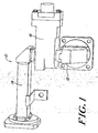
- Figure 1 illustrates an exemplary system of the invention 10 having a first waveguide section 12 that communicates with a second waveguide section 14 through a foreign object damage prevention window module 16.
- Waveguide sections 10, 12 are illustrated as rectangular waveguides, however, they could be made in several types of cross-sectional configurations and can be used, for example, to interconnect components such as an antenna and a receiving unit, or various auxiliary signal conditioning or other components of a radar system including airborne radar systems.
- First waveguide section 12 is a rectangular waveguide with a connecting flange 18 and corner section 20.
- Second waveguide section 14 is also a rectangular waveguide and includes a connecting flange 22 and a corner section 24.
- a person of ordinary skill in the art will recognize that the configuration of these flanges 18, 22 and corner sections 20, 24 can be varied or even removed depending upon the specific application of the system of the invention.
- Foreign object damage prevention window module 16 electromagnetically connects the first and second waveguide sections 12, 14 through a microwave transparent dielectric window 26.
- the illustrated window 26 is disc-shaped and is supported in a generally cylindrical support 28 commonly referred to as a "pillbox.”
- the microwave waveguide sections are rectangular in cross-section and the dielectric window is circular in cross-section.
- Pillbox window designs for connecting rectangular waveguides are well known in the art, for example, U.S. Pat. No. 5,072,202 entitled “Wideband Power Microwave Window with Improved Mechanical and Electrical Behavior” and A. Jostingmeier et al., "Systematic Design of an S-Band Pillbox-Type RF Window," XIX International Linear Accelerator Conference, August 24, 1998. Further, while a pillbox window is described in the illustrated embodiments, a person of ordinary skill will understand that other window designs could be used, including, for example, placing a rectangular window within a rectangular waveguide as is also well known in the art. Regardless of the window design chosen, window 26 should be properly matched to compensate for impedance changes inherent in the structure being employed in the design.
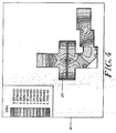
- the pillbox window structure can be built from machined or cast parts, then brazed, soldered or assembled into a single structure as illustrated in FIG. 2 .
- the pillbox window structure can then be brazed into the larger assembly. With the components brazed into a single sealed structure, the structure will have the ability to hold gas pressure as desired.
- the window structure can be designed for use over a broad temperature range by selecting materials having compatible coefficients of thermal expansion. For example, where dielectric window 26 is formed from a ceramic, the window can be supported within cylindrical chamber 28 using a copper diaphragm, mechanically isolating window 26 from the rest of the module 16 assembly so that the ceramic window is not stressed during changes in temperature.
- the system of the invention also includes a gas bypass filtration assembly 30 including one or more gas entry ports 32 in communication with first waveguide 12, an airspace 34 defined between the entry ports 32 and a module housing 35, a first gas path 36 providing a gas pathway from airspace 34 to a filter 38, and a second gas path 40 leading to one or more gas exit ports 42 which communicate with second waveguide 14.
- gas entry ports 32 comprise a plurality of small ports disposed around window support 28 below window 26 in communication with first waveguide section 12.
- Gas entry ports 32 are preferably placed in areas of low electromagnetic wave energy to prevent electric breakdown and unnecessary losses in an electromagnetic signal passing through the waveguides.
- gas entry ports 32 can be sized so as to perform a first pass filtering of the gas traveling through the system by blocking larger particles from passing through the ports. Gas entry ports 32 can also be located around the circumference of window support 28 to reduce the likelihood that the entry ports will become clogged and to allow for the system of the invention 10 to be mounted in a variety of orientations.
- airspace 34 can be designed as an annular chamber that circumscribes support 28 and encompasses a backside of gas entry ports 32. This configuration allows gas flowing through gas entry ports 32 to travel into first gas path 36 and on to filter 38. A person of ordinary skill in the art will recognize that the precise configuration of airspace 34 will depend upon the geometry of the window and gas entry ports selected.
- Filter 38 can be a porous solid filter cup that is U-shaped in cross-section as illustrated in FIG. 2 such as a sintered ceramic or metallic filter element.
- the outside portion of illustrated cup filter 38 communicates with first gas path 36 while the inside portion communicates with second gas path 40.
- Gas bypass filter assembly 30 also includes a cap 44 to close a chamber about the filter and is secured by screws 46 and sealed by O-ring 48. This configuration allows for easy replacement of filters, including for the purpose of providing a filter having different porosity for providing desired filtration or pressure differential results.
- a pressure valve can be included in gas bypass filter assembly 30 if desired to provide a limit for any pressure differential that might occur across window 26.
- the invention results in parallel paths through system 10, one path for microwave transmission and a second path for gas filtering. These two paths are provided within a single, integrated module that can be connected between standard waveguides, resulting in lower part counts, smaller packaging, and higher reliability than other designs.
- the integrated module of the present invention can be connected to standard waveguides and can be used under static pressure, ambient pressure or in a sealed system without degrading the desired pressure system and without degrading the performance of the desired pressure system.
Landscapes
- Physics & Mathematics (AREA)
- Engineering & Computer Science (AREA)
- Plasma & Fusion (AREA)
- Chemical & Material Sciences (AREA)
- Analytical Chemistry (AREA)
- Physical Or Chemical Processes And Apparatus (AREA)
- Processes For Solid Components From Exhaust (AREA)
- Filtering Of Dispersed Particles In Gases (AREA)
- Glass Compositions (AREA)
- Seal Device For Vehicle (AREA)
- Window Of Vehicle (AREA)
Claims (10)
- Système de guide d'ondes pour passer une énergie hyperfréquence tout en filtrant un gaz mobile qui traverse le système, comprenant :des première (12) et seconde (14) parties de guide d'ondes ;une fenêtre hyperfréquence de faible perte (26) disposée entre les première (12) et seconde (14) parties de guide d'ondes afin de permettre le passage de l'énergie hyperfréquence de la première partie de guide d'ondes (12) à la seconde partie de guide d'ondes (14) via la fenêtre hyperfréquence de faible perte (26) ; etun système de filtration de gaz en dérivation (30) ayantun premier orifice (32) en communication avec la première partie de guide d'ondes (12) ;un élément filtrant (38) en communication avec le premier orifice (32) ; etun second orifice (42) en communication avec l'élément filtrant (38) et avec la seconde partie de guide d'ondes (14) ;par lequel un gaz s'écoulant de la première partie de guide d'ondes (12) est bloqué par la fenêtre (26) et s'écoule à travers le système de filtration de gaz en dérivation (30) pour entrer dans la seconde partie de guide d'ondes (14) après avoir traversé le filtre (38) ;caractérisé en ce que :la fenêtre (26) est supportée dans un support de fenêtre entourant (28) ;dans lequel le premier orifice (32) comporte une pluralité de trous dimensionnés de façon à assurer un filtration préliminaire des particules du courant de gaz et disposés autour du support de fenêtre (28) sur un première côté de la fenêtre (26) ; et la fenêtre hyperfréquence et le système de filtration de gaz en dérivation sont fournis dans un module intégré unique.
- Système selon la revendication 1, dans lequel la fenêtre (26) et le système de filtration de gaz en dérivation (30) sont fournis dans un module intégré unique (16).
- Système selon la revendication 1, dans lequel l'élément filtrant (38) est disposé en dehors de toute énergie hyperfréquence traversant le système.
- Système selon la revendication 1, dans lequel les premier (32) et second (42) orifices sont situés dans des régions de faible énergie d'ondes électromagnétiques.
- Système selon la revendication 1, dans lequel l'élément filtrant (38) est remplaçable de façon amovible sans démontage d'aucun composant hyperfréquence.
- Système selon la revendication 1, dans lequel la fenêtre (26) est supportée à l'intérieur du support de fenêtre (28) par une membrane d'isolation mécanique.
- Système selon la revendication 6, comprenant en outre un espace aérien annulaire (34), lequel entoure le support de fenêtre (28) et communique avec le premier orifice (32) ; un premier chemin de gaz (36) qui assure la communication gazeuse entre l'espace aérien annulaire (34) et l'élément filtrant (38) ; et un second chemin de gaz (40) qui assure la communication gazeuse entre l'élément filtrant (38) et le second orifice (42).
- Système selon la revendication 7, dans lequel la fenêtre (26) est circulaire et le support de fenêtre (28) est cylindrique.
- Système selon la revendication 8, dans lequel les première (12) et seconde (14) parties de guide d'ondes ont des sections rectangulaires.
- Système selon l'une quelconque des revendications 1 à 9, dans lequel le système de guide d'ondes est fourni sous forme de système de transmission hyperfréquence à fenêtre de type boîte à pilules et de système de filtration de gaz en dérivation intégrés.
Applications Claiming Priority (3)
| Application Number | Priority Date | Filing Date | Title |
|---|---|---|---|
| US31285701P | 2001-08-16 | 2001-08-16 | |
| US312857P | 2001-08-16 | ||
| PCT/US2002/026082 WO2003017415A2 (fr) | 2001-08-16 | 2002-08-16 | Fenetre pour guides d'onde destinee a empecher des degats dus a la presence d'objets etrangers |
Publications (3)
| Publication Number | Publication Date |
|---|---|
| EP1428287A2 EP1428287A2 (fr) | 2004-06-16 |
| EP1428287A4 EP1428287A4 (fr) | 2005-11-02 |
| EP1428287B1 true EP1428287B1 (fr) | 2008-10-29 |
Family
ID=23213322
Family Applications (1)
| Application Number | Title | Priority Date | Filing Date |
|---|---|---|---|
| EP02770405A Expired - Lifetime EP1428287B1 (fr) | 2001-08-16 | 2002-08-16 | Fenetre pour guides d'onde destinee a empecher des degats dus a la presence d'objets etrangers |
Country Status (7)
| Country | Link |
|---|---|
| US (1) | US6867401B2 (fr) |
| EP (1) | EP1428287B1 (fr) |
| AT (1) | ATE412987T1 (fr) |
| AU (1) | AU2002335641B2 (fr) |
| CA (1) | CA2456227C (fr) |
| DE (1) | DE60229653D1 (fr) |
| WO (1) | WO2003017415A2 (fr) |
Families Citing this family (5)
| Publication number | Priority date | Publication date | Assignee | Title |
|---|---|---|---|---|
| US9357590B2 (en) | 2012-03-14 | 2016-05-31 | Microwave Materials Technologies, Inc. | Microwave heating system with enhanced temperature control |
| US10315126B2 (en) * | 2013-03-14 | 2019-06-11 | Donald W. Ramer | Apparatus for molecular targeting and separation of feedstock fluids |
| US11129243B2 (en) | 2017-03-15 | 2021-09-21 | 915 Labs, Inc. | Multi-pass microwave heating system |
| MX2019011013A (es) | 2017-03-15 | 2019-11-01 | 915 Labs Llc | Elementos de control de energía para calentamiento por microondas mejorado de artículos envasados. |
| SG11201908588QA (en) | 2017-04-17 | 2019-10-30 | 915 Labs Llc | Microwave-assisted sterilization and pasteurization system using synergistic packaging, carrier and launcher configurations |
Family Cites Families (19)
| Publication number | Priority date | Publication date | Assignee | Title |
|---|---|---|---|---|
| US3651622A (en) * | 1968-02-15 | 1972-03-28 | Walter L Wisting | Moisture eliminating apparatus |
| US3846798A (en) | 1968-08-12 | 1974-11-05 | Us Air Force | Integrated window, antenna, and waveguide with plasma alleviation |
| JPS5022865B1 (fr) * | 1969-09-01 | 1975-08-02 | ||
| US3778799A (en) * | 1972-03-28 | 1973-12-11 | Cables De Lyon Geoffroy Delore | Safety device for pipe lines under gas pressure |
| US4286240A (en) * | 1979-12-03 | 1981-08-25 | Varian Associates, Inc. | Circular electric mode microwave window |
| JPS5847680B2 (ja) * | 1979-12-27 | 1983-10-24 | 動力炉、核燃料開発事業団 | 放射性物質用の高周波加熱処理装置 |
| US4500859A (en) * | 1983-04-05 | 1985-02-19 | At&T Bell Laboratories | Filter for existing waveguide structures |
| US4556854A (en) | 1984-06-29 | 1985-12-03 | Litton Systems, Inc. | Microwave window and matching structure |
| US4757292A (en) * | 1986-08-08 | 1988-07-12 | Hughes Aircraft Company | Microwave window |
| JPS63231838A (ja) * | 1987-03-19 | 1988-09-27 | Toshiba Corp | 導波管気密構造体 |
| GB2214720B (en) | 1988-02-01 | 1992-04-08 | Gore & Ass | Waveguides |
| FR2653272A1 (fr) | 1989-10-17 | 1991-04-19 | Thomson Tubes Electroniques | Fenetre hyperfrequence de puissance a large bande, a tenues mecanique et electrique ameliorees. |
| US5313179A (en) * | 1992-10-07 | 1994-05-17 | General Atomics | Distributed window for large diameter waveguides |
| US5346518A (en) * | 1993-03-23 | 1994-09-13 | International Business Machines Corporation | Vapor drain system |
| US5469024A (en) * | 1994-01-21 | 1995-11-21 | Litton Systems, Inc. | Leaky wall filter for use in extended interaction klystron |
| US5471182A (en) * | 1994-08-08 | 1995-11-28 | The United States Of America As Represented By The Secretary Of The Navy | Broadband pressure barrier for circular waveguide |
| JPH10319160A (ja) * | 1997-05-16 | 1998-12-04 | Toshiba Corp | 導波管 |
| US5936493A (en) * | 1997-11-24 | 1999-08-10 | Raytheon Company | Low cost, one-shot switch waveguide window |
| KR100444964B1 (ko) * | 2002-06-29 | 2004-08-21 | 삼성전자주식회사 | 벽걸이형 전자렌지 |
-
2002
- 2002-08-16 EP EP02770405A patent/EP1428287B1/fr not_active Expired - Lifetime
- 2002-08-16 CA CA2456227A patent/CA2456227C/fr not_active Expired - Lifetime
- 2002-08-16 DE DE60229653T patent/DE60229653D1/de not_active Expired - Fee Related
- 2002-08-16 AU AU2002335641A patent/AU2002335641B2/en not_active Expired
- 2002-08-16 US US10/222,255 patent/US6867401B2/en not_active Expired - Lifetime
- 2002-08-16 WO PCT/US2002/026082 patent/WO2003017415A2/fr not_active Ceased
- 2002-08-16 AT AT02770405T patent/ATE412987T1/de not_active IP Right Cessation
Also Published As
| Publication number | Publication date |
|---|---|
| EP1428287A4 (fr) | 2005-11-02 |
| CA2456227C (fr) | 2010-08-10 |
| US20030034345A1 (en) | 2003-02-20 |
| CA2456227A1 (fr) | 2003-02-27 |
| AU2002335641B2 (en) | 2006-04-27 |
| US6867401B2 (en) | 2005-03-15 |
| WO2003017415A2 (fr) | 2003-02-27 |
| WO2003017415A3 (fr) | 2003-11-20 |
| EP1428287A2 (fr) | 2004-06-16 |
| ATE412987T1 (de) | 2008-11-15 |
| DE60229653D1 (de) | 2008-12-11 |
Similar Documents
| Publication | Publication Date | Title |
|---|---|---|
| CA2863046C (fr) | Circulateur a guide d'ondes multijonction sans transitions internes | |
| Kudsia et al. | Innovations in microwave filters and multiplexing networks for communications satellite systems | |
| US6642815B2 (en) | Dielectric resonator filter | |
| CN1137529C (zh) | 具有改进的腔体安排的谐振腔结构 | |
| US20030090344A1 (en) | Dielectric mono-block triple-mode microwave delay filter | |
| US5319329A (en) | Miniature, high performance MMIC compatible filter | |
| CA2629035A1 (fr) | Filtre de guide d'ondes avec large bande affaiblie, reposant sur un mecanisme de substrat de guide d'ondes integre | |
| Zhang et al. | Harmonic-suppressed bandpass filter based on discriminating coupling | |
| US4688009A (en) | Triple-pane waveguide window | |
| EP1428287B1 (fr) | Fenetre pour guides d'onde destinee a empecher des degats dus a la presence d'objets etrangers | |
| US6201453B1 (en) | H-plane hermetic sealed waveguide probe | |
| CA1152587A (fr) | Fenetre pour micro-ondes en mode circulaire electrique | |
| EP1798805B1 (fr) | Assemblages de filtre de résonateur diélectrique et procédés | |
| US10587024B2 (en) | Hermetic sealing of ceramic filters | |
| AU2002335641A1 (en) | Waveguide foreign object damage prevention window | |
| WO2000019628A9 (fr) | Configuration de transducteur/filtre integre en mode orthogonal pour domaine des hyperfrequences | |
| Singh et al. | Enhancing satellite communications: Temperature-compensated filters and their application in satellite technology | |
| US3675165A (en) | Waveguide window for transmission of electromagnetic waves | |
| JP2871725B2 (ja) | 導波管帯域通過フィルター | |
| JPH06511119A (ja) | 狭帯域通過・広帯域消去フィルタ | |
| KR101081419B1 (ko) | 고감도 유전체 공진기 조립체 | |
| US6985047B2 (en) | Continuously tunable waveguide attenuator | |
| US3434076A (en) | Waveguide window having circulating fluid of critical loss tangent for dampening unwanted mode | |
| EP3104451B1 (fr) | Ensemble de résonateur et filtre | |
| CN110459844B (zh) | 一种h面介质可调波导滤波器 |
Legal Events
| Date | Code | Title | Description |
|---|---|---|---|
| PUAI | Public reference made under article 153(3) epc to a published international application that has entered the european phase |
Free format text: ORIGINAL CODE: 0009012 |
|
| AK | Designated contracting states |
Kind code of ref document: A2 Designated state(s): AT BE BG CH CY CZ DE DK EE ES FI FR GB GR IE IT LI LU MC NL PT SE SK TR |
|
| AX | Request for extension of the european patent |
Extension state: AL LT LV MK RO SI |
|
| 17P | Request for examination filed |
Effective date: 20040521 |
|
| A4 | Supplementary search report drawn up and despatched |
Effective date: 20050920 |
|
| RIC1 | Information provided on ipc code assigned before grant |
Ipc: 7H 01P 1/30 B Ipc: 7H 01P 5/02 B Ipc: 7H 01P 1/08 A |
|
| 17Q | First examination report despatched |
Effective date: 20060317 |
|
| 17Q | First examination report despatched |
Effective date: 20060317 |
|
| GRAP | Despatch of communication of intention to grant a patent |
Free format text: ORIGINAL CODE: EPIDOSNIGR1 |
|
| GRAS | Grant fee paid |
Free format text: ORIGINAL CODE: EPIDOSNIGR3 |
|
| GRAA | (expected) grant |
Free format text: ORIGINAL CODE: 0009210 |
|
| AK | Designated contracting states |
Kind code of ref document: B1 Designated state(s): AT BE BG CH CY CZ DE DK EE ES FI FR GB GR IE IT LI LU MC NL PT SE SK TR |
|
| REG | Reference to a national code |
Ref country code: GB Ref legal event code: FG4D |
|
| REG | Reference to a national code |
Ref country code: CH Ref legal event code: EP |
|
| REG | Reference to a national code |
Ref country code: IE Ref legal event code: FG4D |
|
| REF | Corresponds to: |
Ref document number: 60229653 Country of ref document: DE Date of ref document: 20081211 Kind code of ref document: P |
|
| NLV1 | Nl: lapsed or annulled due to failure to fulfill the requirements of art. 29p and 29m of the patents act | ||
| PG25 | Lapsed in a contracting state [announced via postgrant information from national office to epo] |
Ref country code: BG Free format text: LAPSE BECAUSE OF FAILURE TO SUBMIT A TRANSLATION OF THE DESCRIPTION OR TO PAY THE FEE WITHIN THE PRESCRIBED TIME-LIMIT Effective date: 20090129 Ref country code: ES Free format text: LAPSE BECAUSE OF FAILURE TO SUBMIT A TRANSLATION OF THE DESCRIPTION OR TO PAY THE FEE WITHIN THE PRESCRIBED TIME-LIMIT Effective date: 20090209 Ref country code: AT Free format text: LAPSE BECAUSE OF FAILURE TO SUBMIT A TRANSLATION OF THE DESCRIPTION OR TO PAY THE FEE WITHIN THE PRESCRIBED TIME-LIMIT Effective date: 20081029 |
|
| PG25 | Lapsed in a contracting state [announced via postgrant information from national office to epo] |
Ref country code: FI Free format text: LAPSE BECAUSE OF FAILURE TO SUBMIT A TRANSLATION OF THE DESCRIPTION OR TO PAY THE FEE WITHIN THE PRESCRIBED TIME-LIMIT Effective date: 20081029 Ref country code: NL Free format text: LAPSE BECAUSE OF FAILURE TO SUBMIT A TRANSLATION OF THE DESCRIPTION OR TO PAY THE FEE WITHIN THE PRESCRIBED TIME-LIMIT Effective date: 20081029 Ref country code: PT Free format text: LAPSE BECAUSE OF FAILURE TO SUBMIT A TRANSLATION OF THE DESCRIPTION OR TO PAY THE FEE WITHIN THE PRESCRIBED TIME-LIMIT Effective date: 20090330 |
|
| PG25 | Lapsed in a contracting state [announced via postgrant information from national office to epo] |
Ref country code: DK Free format text: LAPSE BECAUSE OF FAILURE TO SUBMIT A TRANSLATION OF THE DESCRIPTION OR TO PAY THE FEE WITHIN THE PRESCRIBED TIME-LIMIT Effective date: 20081029 Ref country code: EE Free format text: LAPSE BECAUSE OF FAILURE TO SUBMIT A TRANSLATION OF THE DESCRIPTION OR TO PAY THE FEE WITHIN THE PRESCRIBED TIME-LIMIT Effective date: 20081029 Ref country code: BE Free format text: LAPSE BECAUSE OF FAILURE TO SUBMIT A TRANSLATION OF THE DESCRIPTION OR TO PAY THE FEE WITHIN THE PRESCRIBED TIME-LIMIT Effective date: 20081029 |
|
| PG25 | Lapsed in a contracting state [announced via postgrant information from national office to epo] |
Ref country code: CZ Free format text: LAPSE BECAUSE OF FAILURE TO SUBMIT A TRANSLATION OF THE DESCRIPTION OR TO PAY THE FEE WITHIN THE PRESCRIBED TIME-LIMIT Effective date: 20081029 Ref country code: SE Free format text: LAPSE BECAUSE OF FAILURE TO SUBMIT A TRANSLATION OF THE DESCRIPTION OR TO PAY THE FEE WITHIN THE PRESCRIBED TIME-LIMIT Effective date: 20090129 Ref country code: IT Free format text: LAPSE BECAUSE OF FAILURE TO SUBMIT A TRANSLATION OF THE DESCRIPTION OR TO PAY THE FEE WITHIN THE PRESCRIBED TIME-LIMIT Effective date: 20081029 |
|
| PLBE | No opposition filed within time limit |
Free format text: ORIGINAL CODE: 0009261 |
|
| STAA | Information on the status of an ep patent application or granted ep patent |
Free format text: STATUS: NO OPPOSITION FILED WITHIN TIME LIMIT |
|
| PG25 | Lapsed in a contracting state [announced via postgrant information from national office to epo] |
Ref country code: SK Free format text: LAPSE BECAUSE OF FAILURE TO SUBMIT A TRANSLATION OF THE DESCRIPTION OR TO PAY THE FEE WITHIN THE PRESCRIBED TIME-LIMIT Effective date: 20081029 |
|
| 26N | No opposition filed |
Effective date: 20090730 |
|
| PG25 | Lapsed in a contracting state [announced via postgrant information from national office to epo] |
Ref country code: MC Free format text: LAPSE BECAUSE OF NON-PAYMENT OF DUE FEES Effective date: 20090831 |
|
| REG | Reference to a national code |
Ref country code: CH Ref legal event code: PL |
|
| PG25 | Lapsed in a contracting state [announced via postgrant information from national office to epo] |
Ref country code: CH Free format text: LAPSE BECAUSE OF NON-PAYMENT OF DUE FEES Effective date: 20090831 Ref country code: LI Free format text: LAPSE BECAUSE OF NON-PAYMENT OF DUE FEES Effective date: 20090831 |
|
| PG25 | Lapsed in a contracting state [announced via postgrant information from national office to epo] |
Ref country code: IE Free format text: LAPSE BECAUSE OF NON-PAYMENT OF DUE FEES Effective date: 20090816 Ref country code: DE Free format text: LAPSE BECAUSE OF NON-PAYMENT OF DUE FEES Effective date: 20100302 |
|
| PG25 | Lapsed in a contracting state [announced via postgrant information from national office to epo] |
Ref country code: GR Free format text: LAPSE BECAUSE OF FAILURE TO SUBMIT A TRANSLATION OF THE DESCRIPTION OR TO PAY THE FEE WITHIN THE PRESCRIBED TIME-LIMIT Effective date: 20090130 |
|
| PG25 | Lapsed in a contracting state [announced via postgrant information from national office to epo] |
Ref country code: LU Free format text: LAPSE BECAUSE OF NON-PAYMENT OF DUE FEES Effective date: 20090816 |
|
| PG25 | Lapsed in a contracting state [announced via postgrant information from national office to epo] |
Ref country code: TR Free format text: LAPSE BECAUSE OF FAILURE TO SUBMIT A TRANSLATION OF THE DESCRIPTION OR TO PAY THE FEE WITHIN THE PRESCRIBED TIME-LIMIT Effective date: 20081029 |
|
| PG25 | Lapsed in a contracting state [announced via postgrant information from national office to epo] |
Ref country code: CY Free format text: LAPSE BECAUSE OF FAILURE TO SUBMIT A TRANSLATION OF THE DESCRIPTION OR TO PAY THE FEE WITHIN THE PRESCRIBED TIME-LIMIT Effective date: 20081029 |
|
| REG | Reference to a national code |
Ref country code: FR Ref legal event code: PLFP Year of fee payment: 15 |
|
| REG | Reference to a national code |
Ref country code: FR Ref legal event code: PLFP Year of fee payment: 16 |
|
| REG | Reference to a national code |
Ref country code: FR Ref legal event code: PLFP Year of fee payment: 17 |
|
| PGFP | Annual fee paid to national office [announced via postgrant information from national office to epo] |
Ref country code: FR Payment date: 20210825 Year of fee payment: 20 |
|
| PGFP | Annual fee paid to national office [announced via postgrant information from national office to epo] |
Ref country code: GB Payment date: 20210827 Year of fee payment: 20 |
|
| REG | Reference to a national code |
Ref country code: GB Ref legal event code: PE20 Expiry date: 20220815 |
|
| PG25 | Lapsed in a contracting state [announced via postgrant information from national office to epo] |
Ref country code: GB Free format text: LAPSE BECAUSE OF EXPIRATION OF PROTECTION Effective date: 20220815 |
|
| P01 | Opt-out of the competence of the unified patent court (upc) registered |
Effective date: 20230731 |