EP1428483A2 - Bracket orthodontique et outil pour libérer un clip - Google Patents
Bracket orthodontique et outil pour libérer un clip Download PDFInfo
- Publication number
- EP1428483A2 EP1428483A2 EP03028121A EP03028121A EP1428483A2 EP 1428483 A2 EP1428483 A2 EP 1428483A2 EP 03028121 A EP03028121 A EP 03028121A EP 03028121 A EP03028121 A EP 03028121A EP 1428483 A2 EP1428483 A2 EP 1428483A2
- Authority
- EP
- European Patent Office
- Prior art keywords
- clip
- main body
- bracket main
- bracket
- arch wire
- Prior art date
- Legal status (The legal status is an assumption and is not a legal conclusion. Google has not performed a legal analysis and makes no representation as to the accuracy of the status listed.)
- Granted
Links
Images




Classifications
-
- A—HUMAN NECESSITIES
- A61—MEDICAL OR VETERINARY SCIENCE; HYGIENE
- A61C—DENTISTRY; APPARATUS OR METHODS FOR ORAL OR DENTAL HYGIENE
- A61C7/00—Orthodontics, i.e. obtaining or maintaining the desired position of teeth, e.g. by straightening, evening, regulating, separating, or by correcting malocclusions
- A61C7/02—Tools for manipulating or working with an orthodontic appliance
-
- A—HUMAN NECESSITIES
- A61—MEDICAL OR VETERINARY SCIENCE; HYGIENE
- A61C—DENTISTRY; APPARATUS OR METHODS FOR ORAL OR DENTAL HYGIENE
- A61C7/00—Orthodontics, i.e. obtaining or maintaining the desired position of teeth, e.g. by straightening, evening, regulating, separating, or by correcting malocclusions
- A61C7/12—Brackets; Arch wires; Combinations thereof; Accessories therefor
- A61C7/28—Securing arch wire to bracket
- A61C7/287—Sliding locks
-
- A—HUMAN NECESSITIES
- A61—MEDICAL OR VETERINARY SCIENCE; HYGIENE
- A61C—DENTISTRY; APPARATUS OR METHODS FOR ORAL OR DENTAL HYGIENE
- A61C7/00—Orthodontics, i.e. obtaining or maintaining the desired position of teeth, e.g. by straightening, evening, regulating, separating, or by correcting malocclusions
- A61C7/12—Brackets; Arch wires; Combinations thereof; Accessories therefor
- A61C7/14—Brackets; Fixing brackets to teeth
- A61C7/145—Lingual brackets
Definitions
- the present invention relates to an orthodontic bracket and a clip release tool, and in particular, for correcting irregular teeth rows or twisted teeth, relates to an orthodontic bracket and a clip release tool.
- the orthodontic bracket has been used for correcting teeth rows.
- a base thereof is provided with a bracket main body.
- the bracket main body is formed with an arch wire slot for receiving an arch wire therein and is furnished with a clip for preventing the arch wire from getting out from the interior of arch wire slot.
- the clip is curved substantially in U-shape and is formed to be engageable in such a manner that a catching end portion formed at an upper distal portion of the clip creeps under a catching part of the bracket main body.
- U.S. Patent 4,698,017 shows an art of rotating a clip by a bar-like tool to release the arch wire slot.
- U.S. Patent 5,562,444 shows an art of releasing a clip rotating round a tie-wing by the bar-like tool inserted in a hole of the clip.
- This publication also discloses a way of pushing to open the front end of the clip by use of a tool (not especially designated).
- U. S. Patent 5, 906, 486 is concerned with a self-ligation bracket of sliding a U-shaped clip and releasing and closing the arch wire slot, and shows an art of inserting the bar-like tool into the hole of the clip for releasing the clip.
- the self-ligation bracket is meant by a bracket where an opening of the arch wire slot is closed with a rotating or sliding clip so that the arch wire does not get out from the interior of the arch wire slot.
- the hole into which the bar-like tool is inserted is formed at about center of the clip, a spring property of the clip is spoiled to reduce force pressing down the arch wire, and besides a problem arises that the clip is easily deformed owing to concentration of stress.
- the invention has been realized. Accordingly it is an obj ect of the invention to offer an orthodontic bracket which enables to prevent the clip from deforming when releasing the clip, and a clip release tool.
- the orthodontic bracket of a first aspect of the invention comprises, a base firmly attachable directly or indirectly to teeth surfaces; a bracket main body equipped on one side of the base; an arch wire slot shaped in groove along mesiodistal direction in the bracket main body, enabling to support an arch wire therein; a substantially belt-like clip curved substantially in U-shape as covering at least one part of an opposite side to the base in the arch wire slot, the clip having a catching end portion for creeping under a cover portion supported by the bracket main body at an upper end part thereof and a recess portion for catching a clip release tool for releasing the clip at the upper end part thereof; and a guide portion formed in at least one of the bracket main body and the base and along a tooth axial direction crossing with the arch wire slot, enabling to guide the clip.
- the orthodontic bracket according to the invention includes an embodiment that.the bracket main body is secured to the face-like base attachable to the teeth surfaces, or an embodiment that the bracket main body is welded, via the base, to a band attached to the teeth surfaces.
- the clip is provided at the upper end part thereof with the recess portion which enables to catch the clip release tool for releasing the clip.
- the position catching the clip release tool is formed to be the recess, so that it is not required to open a hole for the clip to pass through in the thickness direction.
- the clip is substantially U-shaped and narrow in width, it keeps rigidity and can secure spring force to press down the arch wire.
- the clip since the clip is not opened with the hole but formed with the recess portion, concentration of stress is reduced with respect to the clip, and the clip can be prevented from deformation.
- the recess portion is a concave portion which is formed at the upper end part of the clip and does not pass through the clip along thickness.
- the recess portion is made the concave, whereby the clip can be released while being pressing it to the bracket main body, so that the clip is not caused to be deformed, and the recess portion can be comparatively easily formed.
- the recess portion is a cut-and-rising portion where the clip rises along thickness in a direction separating from the bracket main body.
- the recess portion is made the cut-and-rising portion by rising in a direction separating from the bracket main body, so that the recess portion can be comparatively easily formed.
- the clip can be released while being pressing it to the bracket main body by use of an exclusively used tool.
- the recess portion is the cut-and-rising portion where one side of a slit as a boundary formed at the upper end part of the clip rises along thickness in a direction separating from the bracket main body.
- the recess portion is the cut-and-rising portion which causes one side of the slit as the boundary in the direction separating from the bracket main body, whereby the recess portion is comparatively easily formed.
- its front side can be a convex and its inner part can be a concave, so that though not being the exclusively used tool, the clip can be released while being pressing it to the bracket main body.
- the recess portion is formed at an end part of the clip.
- the recess portion is formed at the end part of the clip, whereby the clip can be more easily formed, and the exclusively used tool can be positioned accurately at its front end.
- the recess portion is shaped substantially in a half-spherical dome.
- the recess portion is shaped substantially in the half-spherical dome, whereby the clip release tool can be properly caught by the recess portion, making use of the substantially half-spherical dome.
- the recess portion has a cutout substantially in V-shape at a flat and end part thereof.
- the recess portion is formedwith the cutout, whereby the cutout portion holds the release tool so that the recess portion surely catches the release tool. Therefore, the clip can be more easily released when the clip is released.
- the orthodontic bracket of an eighth aspect of the invention comprises, a base firmly attachable directly or indirectly to teeth surfaces; a bracket main body equipped on one side of the base; an arch wire slot shaped in groove along mesiodistal direction in the bracket main body, enabling to support an arch wire therein; a substantially belt-like clip curved substantially in U-shape as covering at least one part of an opposite side to the base in the arch wire slot, the clip having a catching end portion for creeping under a cover portion supported by the bracket main body at an upper end part thereof and a catching cutout portion substantially in V-shape for catching a clip release tool for releasing the clip at the upper end part thereof; and a guide portion formed in at least one of the bracket main body and the base and along a tooth axial direction crossing with the arch wire slot, enabling to guide the clip.
- the clip is formed at the upper end part thereof with a catching cutout portion substantially in V-shape which enables to catch the clip release tool for releasing the clip, whereby the recess portion can be more easily formed.
- the clip can be easily formed, while the spring force of the clip can influence over the catching ends formed at the upper end parts of the clip extending to both of mesial and distal sides. Therefore, rotation control of the arch wire can be effectively exercised.
- the clip has a contacting portion and the bracket main body has a receiving portion enabling to contact to the contacting portion, and wherein when the clip is released from the bracket main body, the contacting portion contacts to the receiving portion, thereby enabling to regulate a releasing position of the clip from the bracket main body.
- the releasing position of the clip from the bracket main body by the contacting portion and the receiving portion is enabled to be regulated, whereby it is possible to prevent the clip from exceedingly releasing or dropping from the bracket main body.
- the clip release tool of a tenth aspect of the invention for releasing a clip from a bracket main body of an orthodontic bracket, the orthodontic bracket comprising a base firmly attachable directly or indirectly to teeth surfaces, a bracket main body equipped on one side of the base, an arch wire slot shaped in groove along mesiodistal direction in the bracket main body, enabling to support an arch wire therein, a substantially belt-like clip curved substantially in U-shape as covering at least one part of an opposite side to the base in the arch wire slot, the clip having a catching end portion for creeping under a cover portion supported by the bracket main body at an upper end part thereof and a recess portion or a substantially V-shaped catching cutout portion for catching a clip release tool for releasing the clip at the upper end part thereof, and a guide portion formed in at least one of the bracket main body and the base, and along a tooth axial direction crossing with the arch wire slot, enabling to guide the clip, the clip release tool comprising:
- the clip release tool comprises the first projection and the second projection arranged substantially in V-shape.
- the first projection is caught with the recess portion or the catching cutout potion, and the second projection regulates the engagement of the first projection with the recess portion or the catching cutout portion.
- a twin bracket (the bracket having the two cover portions) is exemplified, but the invention is also applicable to a single bracket, and is not limited to the twin bracket only.
- the orthodontic bracket used to a labial side (a lip side) is shown, but also applicable to a lingual side (a tongue side).
- the invention is titled as the orthodontic bracket, but the bracket referred to herein includes a buccal tube for molars, and is not meant by brackets of narrow meaning as for anterior teeth or bicuspids.
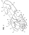
- an orthodontic bracket 10 as a first embodiment of the invention comprises a base 11, a bracket main body 12, an arch wire slot 13, a guide portion 14, and a substantially belt-like clip 20.
- the base 11 is firmly attachable directly or indirectly to teeth surfaces.
- the bracket main body 12 is equipped on one side of the base 11.
- the arch wire slot 13 is shaped in groove in the bracket main body 12.
- the guide portion 14 is formed in at least one of the bracket main body and the base, and along a tooth axial direction crossing with the arch wire slot 13.
- the substantially belt-like clip 20 is guided by the guide portion 14.
- the arch wire slot 13 is formed along the mesiodistal direction of the bracket main body 12.
- the clip 20 is curved substantially in U-shape as covering at least one part of an opposite side to the base in the arch wire slot 13.
- a pair of catching end portions 21 are provided at an upper end part along length of the clip 20.
- a catching groove 15A is provided at the lower part of a cover portion 15 supported by the bracket main body 12. The pair of catching end portions 21 are caught to enable to creep under the catching groove 15A.
- the opposite side to the base is generally designated as the labial side (the lip side), but in a case of the lingual bracket, it is designated as the lingual side (the tongue side).
- the clip 20 is formed to be substantially U-shape with, e.g., a spring thin steel of high corrosion resistance of 0.1 to 0.2 mm thickness.
- a base 22 of the clip 20 is inserted into the guide part 14, while the catching end portions 21 creep into the catching groove 15A under the cover part 15. Therefore the clip 20 is attached to the bracket main body 12 as closing.
- the base 22 is provided with an upper projecting stopper 23 so that, when releasing the clip 20, the base 22 does not get out from the guide part 14.
- the clip 20 is formed with a concave portion 25 as the recess portion in an upper end part 24 between the pair of catching end portions 21.
- the concave portion 25 is used for catching a clip release tool 30 (see Figs. 4 to 7) for releasing the clip 20.
- the clip 20 is not required to have a hole passing through in the thickness direction, so that spring force of the clip 20 can be kept.
- the concave portion 25 of the clip 20 is formed to be larger than a heel portion 31 of the clip release tool 30 for receiving it.
- a toe portion 32 regulates the engagement of the heel portion 31 to the concave portion 25, and at the same time presses down the clip 20, so that it serves to avoid the clip 20 from deformation.
- the toe portion 32 works in a direction of pressing the clip 20 against the bracket main body 12 (see Fig. 1), so that it can be prevented that the clip 20 is turned up by the bar-like tool having referred to concerning the related art, and the clip 20 can be avoided from deformation.
- Fig. 3A the explanation has been made to the example of forming the concave portion 25 to be circular arc, but no limitation is made to this.
- Fig. 3B it is possible to form a position 26 to be deep toward a side of the toe portion 32 in the concave portion 25.
- the heel portion 31 when getting the heel portion 31 into the concave portion 25, the heel portion 31 can be more certainly inserted into the concave portion 31.
- the clip release tool 30 will be referred to on the basis of Figs. 4 to 7B.
- the clip release tool 30 has a left releasing portion 34 and a right releasing portion 35 respectively at left and right end parts of a grip 33.
- the left releasing portion 34 has a heel portion (a first projection) 31 and a toe portion (a second projection) 32, which are disposed substantially in V-shape and in vertical direction.
- the heel portion 31 is positioned to enable to catch the concave portion 25 at the upper end part 24 of the clip 20 (see Figs. 1 and 2).
- the toe portion 32 is positioned to regulate the engagement of the heel portion 31 to the concave portion 25 (see Figs. 1 and 2), and enable to avoid the clip 20 from deformation by pressing down the clip 20 (see Figs. 1 and 2).
- the left releasing part 34 can be used in parallel to the tooth axial direction.
- the heel portion 31 and the toe portion 32 are formed in the same width.
- the right releasing part 35 is provided with a heel portion (the first projection) 37 and a toe portion (the second projection) 38, which are disposed substantially in V-shape and in lateral direction.
- the heel portion 37 is at a position enabling to catch the concave 25 formed in the upper end part 24 of the clip 20 (see Figs. 1 and 2).
- the toe portion 38 is at a position enabling to regulate the engagement of the heel portion 37 with the concave 25 and to avoid deformation of the clip 20 by pressing down the clip 20.
- heel portion 37 and the toe portion 38 are arranged laterally, it is possible to release the clip 20 in the tooth axial direction from a side in a place not permitting to pull toward a front side such as back tooth.
- the heel portion 37 is formed to be narrow in the width and the toe portion 38 is formed to be wide in the width.
- a releasing part 39A may be provided with a column limited in height
- a releasing part 39B may be provided with a half-column limited in height.
- Fig. 8A the operator gets the heel portion 31 of the clip release tool 30 into the concave portion 25. Then, the toe portion 32 regulates fitting of the heel portion 31 in the concave portion 25.
- the clip release tool 30 If moving the clip release tool 30 in a direction of an arrow mark under a condition of getting the heel portion 31 into the concave portion 25, the clip 20 is moved in the arrow direction together with the clip release tool 30.
- the toe portion 32 presses down the clip 20, so that the clip 20 is not turned up, and the clip 20 can be avoided from deformation.
- Fig. 8B the clip 20 is moved together with the clip release tool 30, and the catching end portions 21 get out from the catching groove 15A of the cover 15 to easily move the clip 20 to the releasing position.
- the concave portion 25 provided in the clip 20 at the side of the bracket main body 12 is convex
- the releasing position of.the clip 20 is regulated in that the concave portion 25 contacts, as the convex, a stepwise receiving portion 12A formed in the bracket main body 12. It is possible thereby to avoid an exceeding release or drop of the clip 20 from the bracket main body 12.
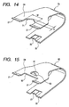
- a clip 40 as the second embodiment of the invention is different from the clip 20 of the first embodiment only in that the clip 40 has, as the recess portion, a cut-and-rising portion 41 rising in a direction separating from the bracket main body 12 (see Fig. 1) along the thickness, and other structures are the same as those of the first embodiment.
- the cut-and-rising portion 41 is made in the direction separating from the bracket main body 12 (see Fig. 1) along the thickness by raising one side of making a boundary a slit 42 formed in the upper end part 24 of the clip 40.
- the other position 43 having the slit 42 as the boundary is raised in the direction approaching the bracket main body 12 along the thickness.
- Fig. 11A the operator disposes the heel portion 31 of the clip release tool 30 neighboring the cut-and-rising portion 41, so that the heel portion 31 contacts the cut-and-rising portion 41.
- the toe portion 32 regulates engagement of the heel portion 31 with the other position 43.
- the toe portion 32 can press down the clip 40 to prevent it from turning up and enable to avoid deformation of the clip 40.
- the other position 43 can be used as a stopper.
- a sliding range is reasonably limited, enabling to prevent the clip 40 from exceedingly releasing.
- a clip 50 as the third embodiment of the invention is different from the clip 20 of the first embodiment only in that the clip 50 has, as the recess portion, a cut-and-rising portion 51 rising in a direction separating from the bracket main body 12 (see Fig. 1) along the thickness, and other structures are the .same as those of the first embodiment.
- the cut-and-rising portion 51 is provided substantially in a half- spherical dome shape at an end part 52 of the clip 50.
- the clip release tool 30 If the clip release tool 30 is moved under a condition of contacting the heel portion 31 (see Fig. 2) to the cut-and- rising portion 51, the clip 50 can be released together with the clip release tool 30.
- a clip 60 as the fourth embodiment of the invention is different from the clip 20 of the first embodiment only in that the clip 60 has, as the recess portion, a cut-and-rising portion 61 raising in a direction separating from the bracket main body 12 (see Fig. 1) along the thickness, and other structures are the same as those of the first embodiment.
- the cut-and-rising portion 61 is provided substantially in a half- spherical dome shape at an end part 62 of the clip 60, and a cutout portion 64 substantially in V-shape is provided in a flat end part 63 of the cut-and-rising portion 61.
- the clip release tool 30 If the clip release tool 30 is moved under a condition of contacting the heel portion 31 (see Fig. 2) to the cut-and-rising portion 61, the clip 60 can be released together with the clip release tool 30.
- the heel portion 31 is held by the cutout portion 64 and can be certainly caught with the cut-and-rising portion 61, so that handling can be more heightened.
- a clip 70 as the fifth embodiment of the invention is different from the clip 20 of the first embodiment only in that the upper end part 24 is provided with a catching cutout portion 71 substantially in V-shape enabling to catch the heel portion 31 (see Fig. 2) of the clip release tool 30 for releasing the clip 70, and other structures are the same as those of the first embodiment.
- the catching cutout portion 71 is determined to be 0.5 to 2.0 mm in width W and 0.3 to 1.0 mm in depth D.
- the clip release tool 30 If the clip release tool 30 is moved under a condition of contacting the heel portion 31 (see Fig. 2) to the catching cutout portion 71, the clip 70 can be released together with the clip release tool 30.
- the heel portion 31 is held by the catching cutout portion 71, so that the handling can be more heightened.
- a clip 80 as the sixth embodiment of the invention is different from the clip 20 of the first embodiment only in that the clip 80 is a cut-and-rising portion 81 rising in a direction separating from the bracket main body 12 (see Fig. 1) along the thickness, and other structures are the same as those of the first embodiment.
- the cut-and-rising portion 81 is provided substantially in a half-spherical dome shape at a part 83 separating from the end part 82 of the clip 80.
- the clip release tool 30 If the clip release tool 30 is moved under a condition of contacting the heel portion 31 (see Fig. 2) to the cut-and-rising portion 81, the clip 80 can be released together with the clip release tool 30.
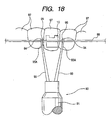
- a clip release tool 90 has, for example, a left releasing portion 34 (see Fig. 4) at the left end part of a grip 91, and a wire releasing portion 92 at the right end part.
- the wire releasing portion 92 has respectively first projections 94 and second projections 95 substantially in V-shape at distal parts 93A of a pair of rods 93.
- the pair of rods 93 are, as shown in Fig. 18, positioned at the front end portions 93A thereof to both sides of the orthodontic bracket 10 disposed on the tooth 97.
- An arch wire 98 is placed between the first and second projections 94, 95 of one rod 93, while the arch wire 98 is similarly placed between the first and second projections 94, 95 of the other rod 93.
- the arch wire 98 can be easily adjusted.
- a seventh embodiment of the orthodontic bracket will be explained on the basis of Figs. 19A to 19C.
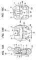
- the orthodontic bracket 100 shown in Figs. 19A to 19C has a bracket main body 120 basically similar to the bracket main body 12 used to the clip release tool 10 of the first embodiment and a clip 200 similar to the clip 50 exemplified in the third embodiment.
- the orthodontic bracket 100 is different from those of the first and third embodiments in that a pair of contacting portions 200A is furnished in the clip 200 and the bracket main body 120 has a pair of receiving portions 120A enabling to contact with the respective contacting portions 200A.
- the contacting portions 200A are provided as cutouts substantially like a crank in flat at an end part of the clip 200 formed as expanding toward the upper end of the clip 200.
- the receiving portions 120A are stepwise portions formed in the surface of the bracket main body 120, and the flat shape thereof corresponds to the flat shape of the contacting portions 200A (see Fig. 19C).
- the contacting portion 200A and the receiving portion 120A contact each other when the clip 200 is released until a predetermined position from the bracket main body 120, thereby to regulate the releasing position of the clip 200 from the bracket main body 120 (see Figs. 19A and 19B).
- the respective contacting portions 200A contact the respective receiving portion 120A. Therefore, the orthodontic bracket 100 regulates the releasing position of the clip 200 from the bracket main body 120, and it is possible to avoid the over-releasing or dropping of the clip 200 from the bracket main body 120.
- the clip is provided at the upper end part thereof with the recess portion which enables to catch the clip release tool for releasing the clip.
- the position catching the clip release tool is formed to be the recess, so that it is not required to open a hole for the clip to pass through in the thickness direction. Thus, it keeps rigidity and can secure spring force.
- the spring force of the clip is secured, and the stress is not concentrated, thereby enabling to avoid the clip from deformation.
- the recess portion is made the concave, so that the recess portion can be comparatively easily formed and the clip can be comparatively easily formed, it is possible to reduce the cost-up, prevent the clip from deformation, and secure the spring force of the clip.
- the recess portion is made the cut-and-rising portion in the direction separating from the bracket main body, so that the recess portion can be comparatively easily formed.
- the clip can be comparatively easily formed, and it is possible to reduce the cost-up, prevent the clip from deformation, and secure the spring force of the clip.
- the recess portion is the cut-and-rising portion which causes one side of the slit as the boundary formed at the upper end part of the clip. to rise along thickness in a direction separating from thebracketmainbody, so that the clip can be comparatively easily formed. It is possible to reduce the cost-up, prevent the clip from deformation, and secure the spring force of the clip.
- the recess portion is formed at the end part of the clip, so that the recess portion can be more easily formed. Therefore, the cost-up can be reduced, and the exclusively used tool can be positioned accurately there at its front end.
- the recess portion is shaped substantially in the half-spherical dome. Therefore, the clip release tool can be easily caught by the recess portion, making use of the substantially half-spherical dome. Thereby, when releasing the clip, it is possible to more easily release the clip.
- the recess portion is formed with the cutout, so that the clip release tool can be easily caught by the recess portion. Thereby, when releasing the clip, it is possible to more easily release the clip.
- the clip is formed at the upper end part thereof with the catching cutout portion substantially in V-shape which enables to catch the clip release tool for releasing the clip. Therefore, the recess portion can be more easily formed, so that the clip can be easily formed, thereby enabling to reduce the cost-up.
- the contacting portion contacts the receiving portion, thereby enabling to regulate the releasing position of the clip from the bracket main body. Therefore, it is possible to prevent the clip from exceedingly releasing from the bracket main body, and the clip from dropping from the bracket main body.
- the clip release tool of the ten aspect of the invention comprises the first projection and the second proj ection arranged substantially in V-shape.
- the first projection is caught with the recess portion or the catching cutout potion, and the second projection regulates the engagement of the first projection with the recess portion or the catching cutout portion.
Landscapes
- Health & Medical Sciences (AREA)
- Oral & Maxillofacial Surgery (AREA)
- Dentistry (AREA)
- Epidemiology (AREA)
- Life Sciences & Earth Sciences (AREA)
- Animal Behavior & Ethology (AREA)
- General Health & Medical Sciences (AREA)
- Public Health (AREA)
- Veterinary Medicine (AREA)
- Dental Tools And Instruments Or Auxiliary Dental Instruments (AREA)
Applications Claiming Priority (2)
| Application Number | Priority Date | Filing Date | Title |
|---|---|---|---|
| US43169302P | 2002-12-09 | 2002-12-09 | |
| US431693P | 2002-12-09 |
Publications (3)
| Publication Number | Publication Date |
|---|---|
| EP1428483A2 true EP1428483A2 (fr) | 2004-06-16 |
| EP1428483A3 EP1428483A3 (fr) | 2005-01-19 |
| EP1428483B1 EP1428483B1 (fr) | 2012-05-23 |
Family
ID=32326652
Family Applications (1)
| Application Number | Title | Priority Date | Filing Date |
|---|---|---|---|
| EP03028121A Expired - Lifetime EP1428483B1 (fr) | 2002-12-09 | 2003-12-05 | Bracket orthodontique et outil pour libérer un clip |
Country Status (3)
| Country | Link |
|---|---|
| US (1) | US7442039B2 (fr) |
| EP (1) | EP1428483B1 (fr) |
| JP (2) | JP4233949B2 (fr) |
Cited By (6)
| Publication number | Priority date | Publication date | Assignee | Title |
|---|---|---|---|---|
| DE102004056168B4 (de) * | 2004-11-18 | 2007-09-06 | Bernhard Förster Gmbh | Selbstligierendes Bracket für die Orthodontie |
| DE202008008095U1 (de) | 2008-05-09 | 2008-11-20 | Tomy Incorporated, Futaba-gun | Clip-Ablösewerkzeug für Zahnspange |
| EP1876991A4 (fr) * | 2005-04-08 | 2009-06-03 | Lancer Orthodontics | Ensemble crochet auto-ligaturant bas profil et procede d'utilisation |
| WO2010083491A1 (fr) | 2009-01-16 | 2010-07-22 | Ormco Corporation | Brackets orthodontiques et procédé de correction de dents mal positionnées |
| EP2705807A1 (fr) | 2012-09-06 | 2014-03-12 | Dental Morelli Ltda. | Mécanisme introduit dans une fixation avec crêtes curvilignes |
| US10751150B2 (en) | 2005-01-11 | 2020-08-25 | Ormco Corporation | Self-ligating orthodontic bracket |
Families Citing this family (51)
| Publication number | Priority date | Publication date | Assignee | Title |
|---|---|---|---|---|
| US7419375B2 (en) | 2002-08-19 | 2008-09-02 | Ormco Corporation | Aesthetic self-ligating orthodontic bracket |
| US7621743B2 (en) * | 2002-11-26 | 2009-11-24 | Orthodontic Research And Development, S.L. | Orthodontic bracket |
| AU2003282122A1 (en) * | 2002-11-26 | 2004-06-18 | Luis Carriere Lluch | Improvements to orthodontic supports applicable to teeth |
| US7993132B2 (en) * | 2002-12-09 | 2011-08-09 | Tomy Incorporated | Orthodontic bracket and clip release tool |
| JP4233949B2 (ja) * | 2002-12-09 | 2009-03-04 | トミー株式会社 | 歯列矯正ブラケットおよびグリップ開放ツール |
| US7186114B2 (en) * | 2004-03-30 | 2007-03-06 | Navarro Carlos F | Self-ligating lingual orthodontic bracket |
| EP1813221B1 (fr) * | 2004-10-29 | 2009-08-19 | Euroortodoncia, S.L. | Bracket à auto-ligaturage avec des pattes laterales |
| FR2882918B1 (fr) * | 2005-03-14 | 2008-02-22 | Charles Clor | Dispositif de correction orthodontique |
| JP3766836B1 (ja) * | 2005-06-03 | 2006-04-19 | 馨 大西 | 歯列矯正器具、ならびにそれに用いられるブラケットおよびキイ |
| US7674110B2 (en) * | 2006-03-23 | 2010-03-09 | Ormco Corporation | Low profile self-ligating orthodontic brackets and methods of using such orthodontic brackets |
| US7704072B2 (en) | 2006-04-19 | 2010-04-27 | Ormco Corporation | Orthodontic bracket |
| US7780443B2 (en) * | 2006-05-04 | 2010-08-24 | World Class Technology Corporation | Self-ligating bracket with rotary cover |
| US7585171B2 (en) * | 2006-05-04 | 2009-09-08 | World Class Technology Corporation | Orthodontic bracket with rotary ligating cover |
| WO2008031060A2 (fr) | 2006-09-07 | 2008-03-13 | Rmo, Inc. | Tube buccal à frottement réduit et procédé d'utilisation |
| US8979528B2 (en) | 2006-09-07 | 2015-03-17 | Rmo, Inc. | Customized orthodontic appliance method and system |
| US8376739B2 (en) * | 2011-05-12 | 2013-02-19 | Rmo, Inc. | Self ligating orthodontic bracket having a rotatable member |
| US9554875B2 (en) | 2006-09-07 | 2017-01-31 | Rmo, Inc. | Method for producing a customized orthodontic appliance |
| EP2008611A1 (fr) * | 2007-06-28 | 2008-12-31 | Ormco Corporation | Outils à main orthodontiques pour une utilisation avec un support orthodontique à ligature automatique, procédés pour l'utilisation de tels outils à main orthodontiques et supports orthodontiques à ligature automatique et systèmes de supports orthodontiques |
| US7845940B2 (en) * | 2007-11-02 | 2010-12-07 | Mark Minium | Orthodontic apparatus with self-ligating bracket and locking device |
| JP5770630B2 (ja) | 2008-08-13 | 2015-08-26 | オルムコ コーポレイション | 審美的歯列矯正ブラケット及びその製造方法 |
| US7963768B2 (en) * | 2008-09-05 | 2011-06-21 | Jack Keith Hilliard | Self-ligating orthodontic bracket assembly |
| WO2010107567A1 (fr) | 2009-03-16 | 2010-09-23 | Rmo, Inc. | Bracket orthodontique doté d'un canal de fil métallique pour arc, et mécanisme de retenue de fil métallique pour arc |
| US11219507B2 (en) | 2009-03-16 | 2022-01-11 | Orthoamerica Holdings, Llc | Customized orthodontic appliance and method |
| US8636507B2 (en) | 2009-06-03 | 2014-01-28 | John C. Voudouris | Self-ligating orthodontic bracket |
| DE102009049659B4 (de) * | 2009-10-09 | 2014-10-30 | Bernhard Förster Gmbh | Selbstligierendes Bracket für die Orthodontie |
| US8162660B2 (en) | 2009-11-20 | 2012-04-24 | Robert T Rudman | Rotating clip orthodontic bracket |
| US20120305668A1 (en) * | 2010-01-29 | 2012-12-06 | Andy Davis | Spray Bottle and Methods of Making and Using the Same |
| US9345558B2 (en) | 2010-09-03 | 2016-05-24 | Ormco Corporation | Self-ligating orthodontic bracket and method of making same |
| US9615897B2 (en) | 2010-09-10 | 2017-04-11 | Ormco Corporation | Self-ligating orthodontic bracket |
| FR2969483B1 (fr) * | 2010-12-28 | 2015-07-31 | H 32 | Ensemble forme par une attache auto-ligaturante et un clip elastique, ensemble forme par cette attache, ce clip et une base, et appareil orthodontique le comportant. |
| FR2969481B1 (fr) * | 2010-12-28 | 2013-11-29 | H 32 | Ensemble attache-clip-base avec base pour appareillage orthodontique et appareil orthodontique le comportant. |
| FR2969482B1 (fr) * | 2010-12-28 | 2013-11-29 | H 32 | Ensemble forme par une attache, un clip et une base pour appareil orthodontique, et appareil orthodontique le comportant |
| BR112013020242A2 (pt) | 2011-02-11 | 2016-10-18 | Orthoarm Inc | suporte ortodôntico |
| USD847349S1 (en) | 2011-09-22 | 2019-04-30 | Rmo, Inc. | Orthodontic lock with flange |
| US9585733B2 (en) | 2012-03-28 | 2017-03-07 | Orthoarm, Inc. | Orthodontic bracket with angled, curved shutter |
| EP2644150B1 (fr) | 2012-03-28 | 2019-01-23 | Orthoarm, Inc. | Support actif à ligature automatique |
| BR302012004589S1 (pt) * | 2012-09-06 | 2014-10-29 | Dental Morelli Ltda | Configuração aplicada em dispositivo ortodôntico |
| US9480541B2 (en) * | 2012-10-09 | 2016-11-01 | Dentsply International Inc. | Self-ligating orthodontic brackets |
| US9468505B2 (en) | 2013-03-15 | 2016-10-18 | American Orthodontics Corporation | Self-ligating bracket |
| WO2014201460A1 (fr) | 2013-06-14 | 2014-12-18 | Ormco Corporation | Bracket orthodontique autoligaturant avec élément de fermeture rotatif |
| JP1518382S (fr) * | 2014-06-10 | 2015-03-02 | ||
| US9504309B2 (en) * | 2014-10-04 | 2016-11-29 | Douglas Ralph | Connector apparatus, system, and method of use |
| US10111731B2 (en) | 2014-11-18 | 2018-10-30 | American Orthodontics Corporation | Self-ligating bracket |
| US9943383B2 (en) * | 2014-12-19 | 2018-04-17 | Ormco Corporation | Biased pivoting slide orthodontic bracket |
| US10080628B2 (en) | 2015-06-08 | 2018-09-25 | American Orthodontics Corporation | Self-ligating bracket |
| USD797294S1 (en) | 2015-11-12 | 2017-09-12 | American Orthodontics Corporation | Self-ligating bracket |
| US9770310B2 (en) | 2016-02-25 | 2017-09-26 | Pbd, Patent & Business Development Ag | Orthodontic self-ligating bracket |
| KR200486668Y1 (ko) * | 2016-11-24 | 2018-06-20 | 문승수 | 치열 교정기의 클립 장탈착기구 |
| CN107019569A (zh) | 2017-05-19 | 2017-08-08 | 吉利 | 自锁托槽及其开启方法 |
| KR102159799B1 (ko) * | 2020-06-16 | 2020-09-24 | 이종형 | 투명 치아 교정장치 |
| USD1035008S1 (en) * | 2022-04-22 | 2024-07-09 | Biocetec Co., Ltd. | Orthodontic bracket |
Citations (3)
| Publication number | Priority date | Publication date | Assignee | Title |
|---|---|---|---|---|
| US4698017A (en) | 1986-12-10 | 1987-10-06 | Hanson Gustaf H | Orthodontic brackets |
| US5562444A (en) | 1994-03-03 | 1996-10-08 | Heiser; Wolfgang | Bracket |
| US5906486A (en) | 1998-05-07 | 1999-05-25 | Hanson; G. Herbert | Self-ligating orthodontic brackets |
Family Cites Families (12)
| Publication number | Priority date | Publication date | Assignee | Title |
|---|---|---|---|---|
| US3076265A (en) * | 1958-03-17 | 1963-02-05 | Harry N Moore | Orthodontic keeper bracket |
| US5039302A (en) * | 1990-02-01 | 1991-08-13 | Johnson & Johnson Consumer Products, Inc. | Dental bracket instrument |
| US5586882A (en) * | 1994-07-12 | 1996-12-24 | Hanson; G. Herbert | Self-ligating orthodontic brackets |
| US20020006595A1 (en) * | 1997-10-20 | 2002-01-17 | Voudouris John C. | Orthodontic tools |
| US6168428B1 (en) * | 1997-11-12 | 2001-01-02 | John C. Voudouris | Orthodontic bracket |
| US6071118A (en) * | 1998-02-17 | 2000-06-06 | Damon Family Limited Partnership | Self-ligating orthodontic bracket |
| US6071119A (en) * | 1998-12-22 | 2000-06-06 | 3M Innovative Properties Company | Dual mode self-ligating orthodontic bracket |
| US6193508B1 (en) * | 1999-03-25 | 2001-02-27 | 3M Innovative Properties Company | Self-ligating orthodontic bracket with enhanced rotation control |
| JP4444410B2 (ja) * | 1999-10-08 | 2010-03-31 | トミー株式会社 | 歯列矯正ブラケットおよび歯列矯正ブラケット用ツール |
| JP4659991B2 (ja) * | 2001-02-28 | 2011-03-30 | トミー株式会社 | 歯列矯正ブラケット |
| JP4411573B2 (ja) * | 2001-08-24 | 2010-02-10 | トミー株式会社 | 歯列矯正ブラケット |
| JP4233949B2 (ja) * | 2002-12-09 | 2009-03-04 | トミー株式会社 | 歯列矯正ブラケットおよびグリップ開放ツール |
-
2003
- 2003-07-28 JP JP2003280766A patent/JP4233949B2/ja not_active Expired - Lifetime
- 2003-12-05 EP EP03028121A patent/EP1428483B1/fr not_active Expired - Lifetime
- 2003-12-09 US US10/730,268 patent/US7442039B2/en not_active Expired - Lifetime
-
2008
- 2008-05-09 JP JP2008122879A patent/JP4833250B2/ja not_active Expired - Fee Related
Patent Citations (3)
| Publication number | Priority date | Publication date | Assignee | Title |
|---|---|---|---|---|
| US4698017A (en) | 1986-12-10 | 1987-10-06 | Hanson Gustaf H | Orthodontic brackets |
| US5562444A (en) | 1994-03-03 | 1996-10-08 | Heiser; Wolfgang | Bracket |
| US5906486A (en) | 1998-05-07 | 1999-05-25 | Hanson; G. Herbert | Self-ligating orthodontic brackets |
Cited By (13)
| Publication number | Priority date | Publication date | Assignee | Title |
|---|---|---|---|---|
| DE102004056168B4 (de) * | 2004-11-18 | 2007-09-06 | Bernhard Förster Gmbh | Selbstligierendes Bracket für die Orthodontie |
| US11065088B2 (en) | 2005-01-11 | 2021-07-20 | Ormco Corporation | Self-ligating orthodontic bracket |
| US10751150B2 (en) | 2005-01-11 | 2020-08-25 | Ormco Corporation | Self-ligating orthodontic bracket |
| EP1876991A4 (fr) * | 2005-04-08 | 2009-06-03 | Lancer Orthodontics | Ensemble crochet auto-ligaturant bas profil et procede d'utilisation |
| DE202008008095U1 (de) | 2008-05-09 | 2008-11-20 | Tomy Incorporated, Futaba-gun | Clip-Ablösewerkzeug für Zahnspange |
| CN102348427B (zh) * | 2009-01-16 | 2014-11-26 | 奥姆科公司 | 正畸托槽以及矫正错位牙齿的方法 |
| US9004916B2 (en) | 2009-01-16 | 2015-04-14 | Ormco Corporation | Orthodontic bracket and method of correcting malpositioned teeth |
| CN104644277A (zh) * | 2009-01-16 | 2015-05-27 | 奥姆科公司 | 正畸托槽以及矫正错位牙齿的方法 |
| EP2387370A4 (fr) * | 2009-01-16 | 2015-08-26 | Ormco Corp | Brackets orthodontiques et procédé de correction de dents mal positionnées |
| US9492247B2 (en) | 2009-01-16 | 2016-11-15 | Ormco Corporation | Orthodontic bracket and method of correcting malpositioned teeth |
| CN102348427A (zh) * | 2009-01-16 | 2012-02-08 | 奥姆科公司 | 正畸托槽以及矫正错位牙齿的方法 |
| WO2010083491A1 (fr) | 2009-01-16 | 2010-07-22 | Ormco Corporation | Brackets orthodontiques et procédé de correction de dents mal positionnées |
| EP2705807A1 (fr) | 2012-09-06 | 2014-03-12 | Dental Morelli Ltda. | Mécanisme introduit dans une fixation avec crêtes curvilignes |
Also Published As
| Publication number | Publication date |
|---|---|
| US7442039B2 (en) | 2008-10-28 |
| JP4233949B2 (ja) | 2009-03-04 |
| JP2004188177A (ja) | 2004-07-08 |
| JP4833250B2 (ja) | 2011-12-07 |
| EP1428483A3 (fr) | 2005-01-19 |
| EP1428483B1 (fr) | 2012-05-23 |
| US20040166458A1 (en) | 2004-08-26 |
| JP2008229367A (ja) | 2008-10-02 |
Similar Documents
| Publication | Publication Date | Title |
|---|---|---|
| US7442039B2 (en) | Orthodontic bracket and clip release tool | |
| US7993132B2 (en) | Orthodontic bracket and clip release tool | |
| JP4467330B2 (ja) | ブラケット | |
| US7255557B2 (en) | Self-ligating bracket for use in orthodontics | |
| US6190166B1 (en) | Orthodontic device | |
| EP1287789B1 (fr) | Bague orthodontique | |
| US8333586B2 (en) | Orthodontic bracket and arrangement for correcting irregularities of the teeth | |
| US8246348B2 (en) | Self-ligating orthodontic bracket | |
| US7967603B2 (en) | Self-ligating orthodontic bracket | |
| JP5926018B2 (ja) | 自己結さつ歯列矯正ブラケット | |
| JP5475440B2 (ja) | パッドを有するブラケット | |
| JP2003527131A (ja) | ポスト及びチューブ歯科器具のための固定機構 | |
| US6033217A (en) | Orthodontic device | |
| US6168429B1 (en) | Orthodontic bracket insert | |
| MXPA06000397A (es) | Bracket para ortodoncia de auto-ligado. | |
| CN113116567A (zh) | 自锁式正畸托槽 | |
| EP2266496A1 (fr) | Support orthodontique | |
| US20020006595A1 (en) | Orthodontic tools | |
| US20040265768A1 (en) | Buccal tube | |
| KR20210114067A (ko) | 치과 교정용 브라켓 | |
| WO2018193829A1 (fr) | Bracket orthodontique | |
| JP2019506975A (ja) | 歯列矯正ブラケット | |
| US20080248440A1 (en) | Orthodontic Bracket | |
| JP2019107204A (ja) | 歯列矯正ブラケット |
Legal Events
| Date | Code | Title | Description |
|---|---|---|---|
| PUAI | Public reference made under article 153(3) epc to a published international application that has entered the european phase |
Free format text: ORIGINAL CODE: 0009012 |
|
| AK | Designated contracting states |
Kind code of ref document: A2 Designated state(s): AT BE BG CH CY CZ DE DK EE ES FI FR GB GR HU IE IT LI LU MC NL PT RO SE SI SK TR |
|
| AX | Request for extension of the european patent |
Extension state: AL LT LV MK |
|
| PUAL | Search report despatched |
Free format text: ORIGINAL CODE: 0009013 |
|
| AK | Designated contracting states |
Kind code of ref document: A3 Designated state(s): AT BE BG CH CY CZ DE DK EE ES FI FR GB GR HU IE IT LI LU MC NL PT RO SE SI SK TR |
|
| AX | Request for extension of the european patent |
Extension state: AL LT LV MK |
|
| 17P | Request for examination filed |
Effective date: 20050321 |
|
| AKX | Designation fees paid |
Designated state(s): DE FR IT SE |
|
| 17Q | First examination report despatched |
Effective date: 20080108 |
|
| GRAP | Despatch of communication of intention to grant a patent |
Free format text: ORIGINAL CODE: EPIDOSNIGR1 |
|
| GRAS | Grant fee paid |
Free format text: ORIGINAL CODE: EPIDOSNIGR3 |
|
| GRAA | (expected) grant |
Free format text: ORIGINAL CODE: 0009210 |
|
| AK | Designated contracting states |
Kind code of ref document: B1 Designated state(s): DE FR IT SE |
|
| REG | Reference to a national code |
Ref country code: DE Ref legal event code: R096 Ref document number: 60340988 Country of ref document: DE Effective date: 20120726 |
|
| REG | Reference to a national code |
Ref country code: SE Ref legal event code: TRGR |
|
| PLBE | No opposition filed within time limit |
Free format text: ORIGINAL CODE: 0009261 |
|
| STAA | Information on the status of an ep patent application or granted ep patent |
Free format text: STATUS: NO OPPOSITION FILED WITHIN TIME LIMIT |
|
| 26N | No opposition filed |
Effective date: 20130226 |
|
| REG | Reference to a national code |
Ref country code: DE Ref legal event code: R097 Ref document number: 60340988 Country of ref document: DE Effective date: 20130226 |
|
| REG | Reference to a national code |
Ref country code: FR Ref legal event code: PLFP Year of fee payment: 13 |
|
| REG | Reference to a national code |
Ref country code: FR Ref legal event code: PLFP Year of fee payment: 14 |
|
| REG | Reference to a national code |
Ref country code: FR Ref legal event code: PLFP Year of fee payment: 15 |
|
| PGFP | Annual fee paid to national office [announced via postgrant information from national office to epo] |
Ref country code: SE Payment date: 20211110 Year of fee payment: 19 Ref country code: FR Payment date: 20211109 Year of fee payment: 19 |
|
| PGFP | Annual fee paid to national office [announced via postgrant information from national office to epo] |
Ref country code: IT Payment date: 20211110 Year of fee payment: 19 |
|
| PGFP | Annual fee paid to national office [announced via postgrant information from national office to epo] |
Ref country code: DE Payment date: 20221102 Year of fee payment: 20 |
|
| REG | Reference to a national code |
Ref country code: SE Ref legal event code: EUG |
|
| PG25 | Lapsed in a contracting state [announced via postgrant information from national office to epo] |
Ref country code: SE Free format text: LAPSE BECAUSE OF NON-PAYMENT OF DUE FEES Effective date: 20221206 |
|
| PG25 | Lapsed in a contracting state [announced via postgrant information from national office to epo] |
Ref country code: FR Free format text: LAPSE BECAUSE OF NON-PAYMENT OF DUE FEES Effective date: 20221231 |
|
| REG | Reference to a national code |
Ref country code: DE Ref legal event code: R071 Ref document number: 60340988 Country of ref document: DE |
|
| PG25 | Lapsed in a contracting state [announced via postgrant information from national office to epo] |
Ref country code: IT Free format text: LAPSE BECAUSE OF NON-PAYMENT OF DUE FEES Effective date: 20221205 |