EP1428541A2 - Stütze für einen Behälter für Infusionsflüssigkeit - Google Patents
Stütze für einen Behälter für Infusionsflüssigkeit Download PDFInfo
- Publication number
- EP1428541A2 EP1428541A2 EP03027262A EP03027262A EP1428541A2 EP 1428541 A2 EP1428541 A2 EP 1428541A2 EP 03027262 A EP03027262 A EP 03027262A EP 03027262 A EP03027262 A EP 03027262A EP 1428541 A2 EP1428541 A2 EP 1428541A2
- Authority
- EP
- European Patent Office
- Prior art keywords
- support
- motor
- height
- magnetic field
- container
- Prior art date
- Legal status (The legal status is an assumption and is not a legal conclusion. Google has not performed a legal analysis and makes no representation as to the accuracy of the status listed.)
- Granted
Links
Images




Classifications
-
- A—HUMAN NECESSITIES
- A61—MEDICAL OR VETERINARY SCIENCE; HYGIENE
- A61M—DEVICES FOR INTRODUCING MEDIA INTO, OR ONTO, THE BODY; DEVICES FOR TRANSDUCING BODY MEDIA OR FOR TAKING MEDIA FROM THE BODY; DEVICES FOR PRODUCING OR ENDING SLEEP OR STUPOR
- A61M3/00—Medical syringes, e.g. enemata; Irrigators
- A61M3/02—Enemata; Irrigators
- A61M3/0266—Stands, holders or storage means for irrigation devices
-
- A—HUMAN NECESSITIES
- A61—MEDICAL OR VETERINARY SCIENCE; HYGIENE
- A61M—DEVICES FOR INTRODUCING MEDIA INTO, OR ONTO, THE BODY; DEVICES FOR TRANSDUCING BODY MEDIA OR FOR TAKING MEDIA FROM THE BODY; DEVICES FOR PRODUCING OR ENDING SLEEP OR STUPOR
- A61M3/00—Medical syringes, e.g. enemata; Irrigators
- A61M3/02—Enemata; Irrigators
- A61M3/0204—Physical characteristics of the irrigation fluid, e.g. conductivity or turbidity
- A61M3/0208—Physical characteristics of the irrigation fluid, e.g. conductivity or turbidity before use
-
- A—HUMAN NECESSITIES
- A61—MEDICAL OR VETERINARY SCIENCE; HYGIENE
- A61M—DEVICES FOR INTRODUCING MEDIA INTO, OR ONTO, THE BODY; DEVICES FOR TRANSDUCING BODY MEDIA OR FOR TAKING MEDIA FROM THE BODY; DEVICES FOR PRODUCING OR ENDING SLEEP OR STUPOR
- A61M3/00—Medical syringes, e.g. enemata; Irrigators
- A61M3/02—Enemata; Irrigators
- A61M3/0204—Physical characteristics of the irrigation fluid, e.g. conductivity or turbidity
- A61M3/0216—Pressure
-
- A—HUMAN NECESSITIES
- A61—MEDICAL OR VETERINARY SCIENCE; HYGIENE
- A61M—DEVICES FOR INTRODUCING MEDIA INTO, OR ONTO, THE BODY; DEVICES FOR TRANSDUCING BODY MEDIA OR FOR TAKING MEDIA FROM THE BODY; DEVICES FOR PRODUCING OR ENDING SLEEP OR STUPOR
- A61M3/00—Medical syringes, e.g. enemata; Irrigators
- A61M3/02—Enemata; Irrigators
- A61M3/0233—Enemata; Irrigators characterised by liquid supply means, e.g. from pressurised reservoirs
- A61M3/0241—Enemata; Irrigators characterised by liquid supply means, e.g. from pressurised reservoirs the liquid being supplied by gravity
-
- A—HUMAN NECESSITIES
- A61—MEDICAL OR VETERINARY SCIENCE; HYGIENE
- A61F—FILTERS IMPLANTABLE INTO BLOOD VESSELS; PROSTHESES; DEVICES PROVIDING PATENCY TO, OR PREVENTING COLLAPSING OF, TUBULAR STRUCTURES OF THE BODY, e.g. STENTS; ORTHOPAEDIC, NURSING OR CONTRACEPTIVE DEVICES; FOMENTATION; TREATMENT OR PROTECTION OF EYES OR EARS; BANDAGES, DRESSINGS OR ABSORBENT PADS; FIRST-AID KITS
- A61F9/00—Methods or devices for treatment of the eyes; Devices for putting in contact-lenses; Devices to correct squinting; Apparatus to guide the blind; Protective devices for the eyes, carried on the body or in the hand
- A61F9/007—Methods or devices for eye surgery
-
- A—HUMAN NECESSITIES
- A61—MEDICAL OR VETERINARY SCIENCE; HYGIENE
- A61M—DEVICES FOR INTRODUCING MEDIA INTO, OR ONTO, THE BODY; DEVICES FOR TRANSDUCING BODY MEDIA OR FOR TAKING MEDIA FROM THE BODY; DEVICES FOR PRODUCING OR ENDING SLEEP OR STUPOR
- A61M2205/00—General characteristics of the apparatus
- A61M2205/33—Controlling, regulating or measuring
- A61M2205/3317—Electromagnetic, inductive or dielectric measuring means
-
- A—HUMAN NECESSITIES
- A61—MEDICAL OR VETERINARY SCIENCE; HYGIENE
- A61M—DEVICES FOR INTRODUCING MEDIA INTO, OR ONTO, THE BODY; DEVICES FOR TRANSDUCING BODY MEDIA OR FOR TAKING MEDIA FROM THE BODY; DEVICES FOR PRODUCING OR ENDING SLEEP OR STUPOR
- A61M2205/00—General characteristics of the apparatus
- A61M2205/33—Controlling, regulating or measuring
- A61M2205/3331—Pressure; Flow
-
- A—HUMAN NECESSITIES
- A61—MEDICAL OR VETERINARY SCIENCE; HYGIENE
- A61M—DEVICES FOR INTRODUCING MEDIA INTO, OR ONTO, THE BODY; DEVICES FOR TRANSDUCING BODY MEDIA OR FOR TAKING MEDIA FROM THE BODY; DEVICES FOR PRODUCING OR ENDING SLEEP OR STUPOR
- A61M2205/00—General characteristics of the apparatus
- A61M2205/33—Controlling, regulating or measuring
- A61M2205/3331—Pressure; Flow
- A61M2205/3344—Measuring or controlling pressure at the body treatment site
-
- A—HUMAN NECESSITIES
- A61—MEDICAL OR VETERINARY SCIENCE; HYGIENE
- A61M—DEVICES FOR INTRODUCING MEDIA INTO, OR ONTO, THE BODY; DEVICES FOR TRANSDUCING BODY MEDIA OR FOR TAKING MEDIA FROM THE BODY; DEVICES FOR PRODUCING OR ENDING SLEEP OR STUPOR
- A61M2209/00—Ancillary equipment
- A61M2209/08—Supports for equipment
- A61M2209/082—Mounting brackets, arm supports for equipment
-
- A—HUMAN NECESSITIES
- A61—MEDICAL OR VETERINARY SCIENCE; HYGIENE
- A61M—DEVICES FOR INTRODUCING MEDIA INTO, OR ONTO, THE BODY; DEVICES FOR TRANSDUCING BODY MEDIA OR FOR TAKING MEDIA FROM THE BODY; DEVICES FOR PRODUCING OR ENDING SLEEP OR STUPOR
- A61M2209/00—Ancillary equipment
- A61M2209/08—Supports for equipment
- A61M2209/084—Supporting bases, stands for equipment
-
- A—HUMAN NECESSITIES
- A61—MEDICAL OR VETERINARY SCIENCE; HYGIENE
- A61M—DEVICES FOR INTRODUCING MEDIA INTO, OR ONTO, THE BODY; DEVICES FOR TRANSDUCING BODY MEDIA OR FOR TAKING MEDIA FROM THE BODY; DEVICES FOR PRODUCING OR ENDING SLEEP OR STUPOR
- A61M2210/00—Anatomical parts of the body
- A61M2210/06—Head
- A61M2210/0612—Eyes
-
- A—HUMAN NECESSITIES
- A61—MEDICAL OR VETERINARY SCIENCE; HYGIENE
- A61M—DEVICES FOR INTRODUCING MEDIA INTO, OR ONTO, THE BODY; DEVICES FOR TRANSDUCING BODY MEDIA OR FOR TAKING MEDIA FROM THE BODY; DEVICES FOR PRODUCING OR ENDING SLEEP OR STUPOR
- A61M3/00—Medical syringes, e.g. enemata; Irrigators
- A61M3/02—Enemata; Irrigators
- A61M3/0202—Enemata; Irrigators with electronic control means or interfaces
-
- A—HUMAN NECESSITIES
- A61—MEDICAL OR VETERINARY SCIENCE; HYGIENE
- A61M—DEVICES FOR INTRODUCING MEDIA INTO, OR ONTO, THE BODY; DEVICES FOR TRANSDUCING BODY MEDIA OR FOR TAKING MEDIA FROM THE BODY; DEVICES FOR PRODUCING OR ENDING SLEEP OR STUPOR
- A61M5/00—Devices for bringing media into the body in a subcutaneous, intra-vascular or intramuscular way; Accessories therefor, e.g. filling or cleaning devices, arm-rests
- A61M5/14—Infusion devices, e.g. infusing by gravity; Blood infusion; Accessories therefor
- A61M5/168—Means for controlling media flow to the body or for metering media to the body, e.g. drip meters, counters ; Monitoring media flow to the body
- A61M5/16804—Flow controllers
- A61M5/16818—Flow controllers by changing the height of the reservoir
Definitions
- the present invention relates generally to an apparatus for ophthalmic surgery, and more particularly to an apparatus for use in ophthalmic surgery with controls to adjust and determine the height of a support coupled to a container from which fluid flows with a desired pressure to a surgical handpiece for the irrigation of a patient's eye.
- Ophthalmic surgery is useful in treating various conditions relating to the eyes.
- One condition which may be alleviated by surgery is cataracts, which are sometimes described as clouding of the eyes.
- cataracts As old cells die, they accumulate within a capsule containing the lens of the eye. This accumulation of dead cells causes an occlusion of the lens, i.e., a cataract.
- a solution or fluid is used to irrigate the eye.
- Operating and controlling a system to deliver or provide the solution can be an issue, and the systems may be complex.
- initial calibrations may be required in order to regulate the supply of the solution. Performing these initial calibrations may slow operation times. Additionally, at times, it is useful to identify the position of a container for the solution to regulate fluid pressure and/or an amount of fluid being supplied.
- the present invention provides an apparatus for use in ophthalmic surgery in which a container for fluid is connected to a line through which fluid flows to a surgical handpiece for the irrigation of a patient's eye.
- the apparatus may comprise a base, a support, an encoder and a controller.
- the support extends from the base and is coupled to the container from which fluid is supplied to the surgical handpiece.
- the encoder can be arranged to determine the absolute position of the support and the controller can be arranged to adjust the height of the support based on the absolute position determined, whereby accurate determination and adjustment of the height of the support ensures that the fluid from the container flows with a desired pressure to the surgical handpiece and into the patient's eye.
- an apparatus for use in ophthalmic surgery in which a container for fluid is connected to a line through which fluid flows to a surgical handpiece for the irrigation of a patient's eye.
- the apparatus comprises means for supporting the container, such as a pole and/or hanger, from which fluid is supplied to the surgical handpiece, means for determining the absolute position of the means for supporting the container with reference to a base, such as a magnet, signal conditioner and a waveguide, and means for adjusting the height of the support based on the absolute position determined, such as a control board and/or motor, whereby accurate determination and adjustment of the height of the support ensures that the fluid from the container flows with a desired pressure to the surgical handpiece and into the patient's eye.
- a further aspect of the invention provides a means for emitting a first magnetic field, such as a magnet, proximate the container and a means for emitting a second magnetic field to interact with the first magnetic field, such as a signal conditioner and waveguide.
- an apparatus for use in ophthalmic surgery in which a container for fluid is connected to a line through which fluid flows to a surgical handpiece for the irrigation of a patient's eye.
- the apparatus comprises a support, a motor and circuitry.
- the support is coupled to the container from which fluid is supplied to the surgical handpiece.
- the motor generates an electro motive force and the circuitry is arranged to prevent vertical movement of the support based on the force generated, whereby the prevention of vertical movement of the support ensures that irrigation fluid from the container flows with a desired pressure to the surgical handpiece and into the patient's eye.
- an apparatus for use in ophthalmic surgery in which a container for fluid is connected to a line through which fluid flows to a surgical handpiece for the irrigation of a patient's eye.
- the apparatus comprises a support, a motor and circuitry.
- the support is coupled to the container from which fluid is supplied to the surgical handpiece.
- the motor is arranged to vertically move the support and the circuitry is arranged to supply a current to the motor to prevent vertical movement of the support, the current supplied having a magnitude that is proportional to a force applied to the motor by the weight of the support, whereby the prevention of vertical movement of the support ensures that fluid from the container flows with a desired pressure to the surgical handpiece and into the patient's eye.
- an apparatus for use in ophthalmic surgery in which a container for fluid is connected to a line through which fluid flows to a surgical handpiece for the irrigation of a patient's eye.
- the apparatus comprises a pole for supporting a container, a magnet for generating a first magnetic field and a carrier housing the magnet and coupled to a portion of the support.
- the apparatus also includes a waveguide proximate the pole containing magnetostrictive strain material and a signal conditioner arranged to cause current to flow through the waveguide to emit a second magnetic field and further arranged to detect a pulse generated from the interaction of the first magnetic field and a second magnetic field.
- the motor can have windings and can be arranged to adjust the height of the pole and the carrier.
- a control board is also arranged to determine the height of the pole based on a time interval between the flow of current to the detection of the pulse by the signal conditioner and further arranged to energize the motor to adjust the length of the pole.
- transistor drivers are arranged to supply drive currents to the windings of the motor and transistor switches are arranged to deactivate the drivers and to supply a current to one of the windings to prevent movement of the motor, whereby accurate determination and adjustment of the height of the support ensures that the fluid from the container flows with a desired pressure to the surgical handpiece and into the patient's eye.
- Another aspect of the invention is a method for use in ophthalmic surgery in which a container for fluid is connected to a line through which fluid flows to a surgical handpiece for the irrigation of a patient's eye.
- the method comprises attaching to a support the container from which fluid is supplied to the surgical handpiece, supplying a current, preventing change of the height of the support by adjusting the current supplied, the current supplied having a magnitude that is proportional to the force exerted by the weight of the support, whereby the prevention of the change of height of the support ensures that fluid from the container flows with a desired pressure to the surgical handpiece and into the patient's eye.
- a method for use in ophthalmic surgery in which a container for fluid is connected to a line through which fluid flows to a surgical handpiece for the irrigation of a patient's eye.
- the method attaches to a support the container from which fluid is supplied to the surgical handpiece, detects the absolute position of the support with reference to a base and adjusts the height of the support based on the absolute position detected, whereby accurate determination and adjustment of the height of the support ensures that the fluid from the container flows with a desired pressure to the surgical handpiece and into the patient's eye.
- a method for use in ophthalmic surgery in which a container for fluid is connected to a line through which fluid flows to a surgical handpiece for the irrigation of a patient's eye.
- the method comprises attaching to a support the container from which fluid is supplied to the surgical handpiece, generating an electro motive force and preventing change of the height of the support based on the force generated, whereby the prevention of the change of height of the support ensures that fluid from the container flows with a desired pressure to the surgical handpiece and into the patient's eye.
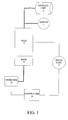
- a telescoping pole 5, shown schematically in FIG. 1, forms a height adjustable support.
- the pole is attached to a base 15, with the length of the pole adjustable.
- a lower section of the pole is adapted to be mounted to a base, such as on a console or cart that can be placed on the floor.
- An upper section of the pole extends in a telescoping manner from the lower section, and the amount of extension is selectable.
- a drive unit 9 is coupled to the pole 5 and is configured to adjust the height of the pole. For example, the drive unit, when actuated, engages the lower section of the pole. The lower section of the pole engages the upper section of the pole to cause the upper section to extend from the lower section of the pole.
- a storage unit 3 is also coupled to the pole 5.
- the storage unit comprises one or more containers, such as bottles or bags, holding a fluid such as a saline solution. In some embodiments, these containers are suspended from the top of pole. Fluid from the container is used to irrigate a patient's eye (not shown). The fluid pressure at the eye is dependent on the height of the pole from which the solution is suspended relative to the patient.
- a detector 13 and a sensor 7 provide a signal indicative of the relative vertical position of the storage unit 3 and the base 15.
- the detector 13 is fixed in position relative to the base 15.
- the sensor 7, although movable, is fixed in position relative to the pole 5. In some embodiments placement of the detector and sensor are reversed. Height adjustment of the pole with respect to the base results in relative movement of the sensor with respect to the detector.
- the controller 11 causes the drive unit 9 to adjust the pole 5 based on information from the detector 13.
- the sensor and detector together act as an absolute encoder that provides an absolute position of the storage unit or a portion of the pole.
- the absolute position is defined as the distance between the detector 13 and the sensor 7 measured along the pole.
- the determination of the absolute position may be accomplished with reference to a predetermined offset or location, such as an offset of distance between the detector and the base and/or an offset of distance between the sensor and the storage unit.
- the absolute position is also determined without determining previous locations of the pole 5 or actuation of the drive unit 9.
- the controller 11 determines the height of the pole 5 or the amount of fluid pressure desired or expected by a user, such as a surgeon. As such, based on the absolute position determined and the height expected, the controller 11 causes the drive unit 9 to extend or retract the pole 5 in a vertical direction, e.g., up or down.
- the detector 13 generates a current pulse.
- the current pulse travels through a waveguide (not shown) coupled parallel to the pole 5.
- a traveling magnetic field is generated by the current pulse, with the magnetic field traveling through the waveguide.
- the sensor 7 is configured to generate another magnetic field.
- the traveling magnetic field interacts with the other magnetic field as the traveling field moves along the waveguide.
- the interaction with the two magnetic fields results in a strain pulse that is received or detected by the detector 13.
- the strain pulse induces current, a magnetic field, or mechanical force along the waveguide.
- the amount of time from the initiation of the current pulse from the detector to the receipt of the strain pulse is proportional to the distance between the detector 13 and the sensor 7.
- the controller 11 determines the distance between the sensor and the detector.
- an absolute encoder e.g., the detector 13 and sensor 7 is described in U.S. Patent No. 3,898,555, the disclosure of which is hereby incorporated by reference. Therefore, a position or height of the pole can be identified quickly and reliably without approximations or initial calibrations.
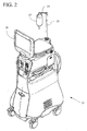
- a pole 23 is mounted on a console 21, as shown in FIG. 2, so as to extend upwardly from the console.
- the console also houses a motor (not shown) used to move or adjust the length of telescoping pole 23.
- the pole 23 extends upward from the console 21.
- a hanger 25 is attached to the pole near the top and supports a container 27.
- the container is filled with, for example, a saline solution. Fluid from the container is delivered to a surgical handpiece for administration to the eye of a patient.
- a monitor 29 is also connected to and mounted on the console 21 to provide feedback, graphical and/or textual information, regarding the surgical procedure and other status data, including the height of the pole. Through the monitor and a touch screen on the monitor or through other input devices, the user can monitor and adjust the height of the pole to adjust, for example, the flow rate of the fluid from the container and the pressure at the eye.
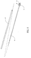
- FIG. 3 illustrates another apparatus in accordance with the invention, for use in ophthalmic surgery.
- This apparatus includes a pole 33.
- a motor 31 is coupled to the pole 33, with the motor configured to adjust the height of the pole in a telescoping manner.
- the motor 31 is connected to pulleys 135a, b and a pulley belt 137. When energized, the motor 31 rotates which causes a shaft (not shown) to rotate. On the end of the shaft not attached to the motor, the pulley 135a is attached. The pulley 135a therefore also rotates in a corresponding manner as the motor rotates.
- Pulley belt 137 couples pulley 135a to pulley 135b which transfers the rotational motion of pulley 135a to pulley 135b.
- pulley 135b also rotates.
- the pulley 135b is coupled to the pole 33 via a lead screw (not visible).
- the lead screw As the lead screw is rotated by pulley 135b, the screw threads engage the pole causing the pole's height to be adjusted. Therefore, depending on the motor turning clockwise, for example, the pole extends and with the motor turning counter clockwise, the pole is retracted.
- a control board 35 is also coupled to the pole 33 and, as illustrated, adjacent to the motor 31.
- the control board receives a signal from a detector head 37.
- the detector head is coupled to a detector controller 39 via input/output cables 131.
- the detector controller and the control board are a single component.
- a waveguide extends parallel to the pole, with the waveguide covered by a support assembly 133. Also covered by the support assembly is a magnet (not shown) which is movable along the waveguide. The support assembly prevents the magnet and/or waveguide from interfering with other components and vice versa.
- a detector head 45 is coupled to one end of the waveguide 41, shown in FIG. 4.
- a magnet 43 substantially surrounds the waveguide and is moveable longitudinally along the waveguide.
- the detector head 45 is coupled to a signal conditioner or detector controller 49 via input cables 47.
- the detector controller 49 is also coupled to a control unit (not shown) via output cables 141.
- a current pulse generated by the detector head 45 causes a magnetic wave to travel through the waveguide 41. This wave interacts with a magnetic field generated by the magnet 43 to cause a strain pulse to travel back toward the detector head 45.
- the detector head senses the strain pulse and provides a return signal to the detector controller 49.
- the detector controller and the control unit are integrated and output cables 141 are therefore not utilized.
- a magnet 53 such as the magnet shown in FIG. 4, is assembled with or embedded in a moveable element 51, such as a carrier nut.
- the moveable element is coupled to a lead screw 55.
- the lead screw is coupled to a portion of the pole 57.
- the carrier nut and the associated magnet moves as the lead screw moves.
- the motor 31 moves or rotates the lead screw 55 which moves the carrier nut with the magnet and the pole. In turn, the position of the container, supported by the pole, moves correspondingly.
- the magnet 53 shown in FIG. 5, and other associated components, including motor 67 and portions of the pole 69, in FIG. 6, are shown assembled in a support structure or assembly 601.
- a waveguide 61 is coupled on one end to a detector head 63 and threaded through a clamp 65a until the detector head is seated next to the clamp.
- the waveguide is also inserted into the support assembly and threaded through the magnet (not shown) in the assembly.
- Another clamp 65b is coupled to the other end of the waveguide, opposite of the detector head.
- the clamps 65a,b couple the waveguide to the support assembly to keep the waveguide and detector head substantially stationary.
- FIG. 7 illustrates an apparatus for use in ophthalmic surgery to supply liquid from a container for the liquid.
- the apparatus includes a detector head 73, a motor 75 and a controller 77.
- a magnet, waveguide and carrier nut are also included but are not visible.
- a bottle hanger 71 extends from a pole 79 and suspends a bottle of fluid (not shown) for delivery to a patient's eye.
- the detector head 73 generates an interrogating current pulse through the waveguide (not shown). As a result, a magnetic field is generated and propagated along the waveguide.
- the waveguide contains a magnetostrictive strain material.
- the magnet (not shown) also generates a magnetic field. The interaction with the two magnetic fields results in a strain pulse that is sensed by the detector head 73. Based on the amount time from the generating the current pulse and receiving of the strain pulse, a detector controller (not shown) is able to determine the distance between the magnet and the detector head element.
- the detector controller includes a pulse width modulator (not shown).
- the pulse width modulator generates a pulse signal, e.g., a voltage square or rectangular wave, based on the interaction of the two magnetic fields.
- the pulse signal is provided to the controller 77.
- the controller 77 measures the pulse width of the pulse signal to determine the absolute position of the magnet relative to the detector head 73.
- a timer or counter (not shown) is initiated to determine a number of counts starting from one edge of the pulse signal to the next edge of the pulse signal. Based on the number of counts, the height of the pole is calculated or compared to values or calculations stored in a memory (not shown) to convert the number of counts into distance units, such as centimeters.
- seventeen counts may correspond to one centimeter.
- the controller 77 determines that the pulse width is fifty counts long, then the pole 17 is about three centimeters away from a predetermined location.
- the predetermined location may be the location of detector head 73 or an offset, such as a particular zero position or set position, e.g., the location of clamp 65b (FIG. 6).
- the magnet since the magnet (not shown) correspondingly moves with the pole 79, the absolute position of the magnet corresponds to or, in one embodiment, is proportional to the current length of the pole.
- the controller 77 in conjunction with the positional information provided by the detector controller causes the motor 75 to move the pole 79 in a particular direction and for a specific distance.
- the detector controller and the controller are described as separate units, both units may be provided as a single controller.
- a process of providing liquid to a patient is diagramed.
- the process determines or checks the height of a container.
- a control unit starts an initialization process by causing strain pulse to be generated, measures the absolute position of the position of the container and displays the position to a user via a console display.
- the process determines if the position of the container is to be modified. The user or system determines or provides input for a desired height of the container or a desired amount or flow rate of liquid. If it is determined that the position of container is to be adjusted, the process continues to block 85. Otherwise, the process returns or ends.
- the process adjusts a structure, e.g., the pole and/or a support structure, supporting the container.
- the process determines the position of the container. In one embodiment this is accomplished in the manner of the determination made in block 81.
- the process determines if the position of the structure is correct, i.e., if the container is at the position desired by the system or user. If so the process ends or returns. Otherwise, the process returns to block 85 to continue to adjust the structure.
- the process also continually repeats and ends or returns when externally commanded or interrupted.
- the process continuously monitors the position of the container to test for faults, e.g., the container is moving when it should be stationary.
- the amount of liquid (intraocular or intravenous liquid) flowing is maintained or regulated by the adjustment of the height of the container or a structure, e.g., a pole and/or a support structure, supporting the container.
- the container, from which liquid is supplied is raised or positioned higher than a predetermined position to increase the flow of the liquid.
- the container, from which the liquid is supplied can be positioned lower relative to a predetermined position to decrease the flow of the liquid.
- the process continuously monitors the height of the pole and automatically adjusts the height of the pole to maintain a constant flow of liquid to a patient.
- FIG. 9 illustrates other aspects of the invention.
- a motor controller 91 is coupled to motor sensors (not shown) and power amplifiers 93.
- the power amplifiers provide phase power to a motor 901.
- the motor sensors such as hall effect sensors, provide positional information regarding the motion or rotation of the motor 901.
- the motor controller 91 in one embodiment, causes DC power to be supplied to the power amplifiers 93 to energize or operate the motor 901 based on the positional information provided or detected by the motor sensors. For example, the motor sensors provide feedback to the motor controller to determine if the motor requires more or less power to rotate a specific or desired number of turns.
- the motor controller 91 is also coupled to dynamic brake circuitry 95.
- the dynamic brake circuitry receives signal input from the motor controller and a micro control unit 97. As such, in cooperation or individually, the motor controller and/or the control unit is able to activate or affect the dynamic brake circuitry.
- the motor controller 91 and the micro control unit 97 are described and shown separately, the motor controller 91 and micro control unit 97 may be a single unit.
- the dynamic brake circuitry 95 is also coupled to the motor 901. Thus, based on enable or command signals from the motor controller 91 or micro control unit 97, the dynamic brake circuitry 95 is configured to energize or cause the motor to operate. In one embodiment, the dynamic brake circuitry 95 causes the motor 901 to turn or exert force to prevent movement of a pole (not shown) or other components coupled to the motor 901 and the pole.
- the micro control unit 97 receives an external input from an input bus, such as a CAN bus, and a detector 13 /sensor 7 (FIG. 1), such as an absolute encoder. Based on input from the input bus, the micro control unit is configured to cause the motor 901 to move or rotate for a particular number of turns and/or time to adjust a pole or components associated with the pole.
- the detector/sensor (not shown) provides absolute position information regarding, for example, the height or vertical displacement of a pole.
- the micro control 97 can continually cause the motor to rotate until the desired extension of the pole is detected by the detector/sensor. Once the desired position is achieved, the micro control unit 97 is configured to command or otherwise cause the motor controller 91 to stop the motor 901.
- the micro control unit can active the dynamic brake circuitry 95. For example, if the micro control unit 97 determines that the pole has reached a desired height and/or the micro control unit has commanded the motor 901 to stop, any change in position as reported or detected by the detector/sensor indicates that the motor and/or pole is moving. Thus, the dynamic brake circuitry can be activated to maintain a particular position or prevent a change in a particular position and maintain a desired fluid pressure, if any.
- a static brake circuitry 99 is also coupled to the motor 901 and a power source or input (not shown). The supplied power can be used to energize the motor.
- the static brake circuitry detects or senses when power to the motor 901 is removed or lost. As such, in response to power being removed or lost, the static brake circuitry 99 causes the motor to resist movement by shorting one or more windings of the motor. By shorting windings of the motor, an electro motive force is generated by the motor to resist or prevent movement of a pole or other components coupled to the motor and/or the pole.
- a mechanical brake (not shown) is also provided.
- the mechanical brake is coupled to the motor 901 and/or pole (not shown) and a power source or input (not shown).
- the power source or input can be the same power source or input supplying power to energize the motor.
- the mechanical brake is activated to stop or prevent movement of the motor and/or pole.
- the pulleys, rotors or other components of the motor 901 or pole are impeded by clamping components together, such as clamping movable components to stationary components.
- FIG. 10 is a schematic diagram of circuitry to actuate and prevent actuation of a motor coupled to a pole.
- Power amplifiers or drivers 101a-c provide drive currents to the motor, such as a three phase brushless DC motor (not shown).
- the motor contains windings and hall effect sensors that, when energized, causes the motor to rotate.
- a motor controller 103 is also coupled to the drivers 101a-c. The controller receives input from the sensors and input from a micro control unit (not shown) which provides commands or input to the controller, for example, to actuate the motor at a particular rate or speed.
- the controller 103 In response, the controller 103 generates drive signals that cause the drivers 101a-c to supply current to the motor to cause the motor to rotate in a particular direction and velocity, e.g., by varying the amplitude and phase of the drive currents supplied to the motor. As a result, a pole (not shown) coupled to the motor (not shown) correspondingly extends or retracts at a particular rate. Likewise, the motor can be commanded or controlled to maintain a particular position or prevent any change in position.
- the drivers 101a-c provide push/pull drive signals that source or sink motor drive currents to rotate the motor.
- driver 101c provides a tri-state drive signal.
- the motor is a single phase motor or another type of multi-phase motor. Power is supplied to each driver from a DC to DC converter (not shown).
- the drivers are complementary, N-type and P-type, metal-oxide-silicon (NMOS and PMOS) switches or transistors.
- the drivers 101a-c are also separately coupled to a relay 105.
- the relay is coupled to a power supply or power supply input to monitor whether power is being supplied. As such, under operating conditions, the relay is opened as it is energized by the supplied power.
- the relay is also coupled to ground separately at each corresponding point where power or each driver is coupled to the relay 105. Thus, in the event that power is lost, the relay closes and paths to ground are opened. As such, phase power is not supplied by the drivers 101a-c to the motor and at least one winding of the motor coupled to the drivers is shorted.
- the motor With one or more windings of the motor shorted and force or gravity being exerted by the pole coupled to the motor, the motor generates an electromotive force that resists movement of the motor and thus the pole remains stationary.
- friction due to the coupling of the pole and motor and other components also assist in preventing adjustment of the pole.
- the controller 103 is also coupled to a drain of a transistor 195b.
- the transistor 195b is gate coupled to the drain of transistor 195a.
- the transistors 195a,b are each source coupled to ground. The transistors act as switches that turn on based on their gate input.
- Transistor 195a receives a lock signal via its gate.
- the lock signal is an overriding or master signal to ensure the motor 901 (FIG. 9) is prevented from rotating, i.e., braking is established.
- the lock signal is asserted to identify a fault or error condition. Under normal operations, the lock signal is not asserted.
- transistor 195a turns on and in turn transistor 195b turns off.
- the transistor 195b causes the controller to initiate braking.
- the controller generates brake signals to prevent the drivers 101a-c from generating drive currents to the motor.
- the controller tri-states the top PMOS transistors of the drivers 101a-c which also shorts the bottom NMOS transistors to short the motor windings to ground.
- Transistor 107a is gate coupled to the drain of transistor 195a.
- the transistor 107a is also source coupled to ground and the drain of the transistor is coupled to the gates of transistors 107b and 107c.
- the transistors 107b and 107c are similarly coupled as transistor 107a.
- transistor 107b is drain coupled to an input of driver 101c.
- Transistor 107c is source coupled to an output of driver 101c via diode 109 and resistor 191a.
- the transistors function as switches that turn on based on their gate input. As such, based on the state of transistor 195a, the transistor 107a turns on or off. For example, when transistor 195a is on, transistor 107a turns off.
- transistor 107b turns on and transistor 107c turns on.
- the transistor 107b ensures deactivation of the driver 101c.
- transistor 107c is coupled to resistors 191b-d that are supplied differing voltage inputs.
- transistor 107c couples a five voltage input to the motor via resistor 191a and diode 109a and thus supplies a holding current to the motor that resists rotation of the motor and/or height adjustment of a pole (not shown) coupled to the motor.
- the current supplied is proportional to the force applied to the motor.
- Transistor 107a is also gate coupled to a brake control input.
- the lock signal is low.
- transistor 195a is off.
- the braking operation is controlled. For example, when the brake control signal is low or not asserted, braking circuitry is applied. As such, transistor 195b and 107a are turned off. Subsequently, transistors 107b and 107c are turned on. Thus, as described above, transistor 107b ensures the deactivation of driver 101c and a holding current is applied to the motor via transistor 107c.
- the brake control signal is high, braking circuitry is deactivated.
- transistor 195b and 107a are turned on. Subsequently, transistors 107b and 107c are turned off. Thus, the holding current via transistor 107c is removed or not applied and transistor 107b does not effect the operation of driver 101c.
- the transistors described above are N-type field effect transistors. Other types of transistors may be utilized with a modification in the wiring or coupling of the transistors to various other components, inputs and itself. In other embodiments, other similarly coupled transistors are provided and coupled to the transistors 107a-c, to provide additional control input to active the braking of the motor. In another aspect of the invention, light emitting diodes, such as diodes 193a,b, are coupled to the relay and/or transistors to provide status information, such as indicating that the relay is open or closed.
- a process of preventing movement of a pole or support used to supply liquid to a patient is diagramed.
- the process determines or checks whether power is being supplied or is lost.
- a relay is tripped to indicate that power is lost.
- the process is notified from an external source that power is about to be lost, i.e., the system is to be shutdown. If the process determines that power is lost or will be lost, the process activates static braking to prevent movement of the pole in block 113. In one aspect, a mechanical brake is also activate in block 115. If the process determines that power is not lost, the process continues to block 117.
- the process determines the position or a change in position of the pole.
- the process reads or is provided the absolute position information of the pole or container coupled to the pole from an encoder, e.g., detector 13 and sensor 7 (FIG. 1). If the process determines that the position of the pole has changed or is not a expected position, the process, in block 119, activates a dynamic braking to adjust the pole to place the pole at the expected position or to prevent any change in position.
- the process repeats to block 117 to check again the position of the pole. In one embodiment, the process continues back to block 111 to check again if power is being supplied. If the process determines that the position of the pole has not changed or is as expected, the process ends or returns. In one aspect, the process continually repeats and ends or returns when externally commanded or interrupted.
- the present invention provides methods and apparatus for use in ophthalmic surgery.
- this invention has been described in relation to certain specific embodiments, many additional modifications and variations will be apparent to those skilled in the art. It is, therefore, to be understood that this invention may be practiced otherwise than as specifically described.
- the present embodiments of the present invention should be considered in all respects as illustrative and not restrictive. The scope of the invention is to be determined by the appended claims, and their equivalents rather than the foregoing description.
Landscapes
- Health & Medical Sciences (AREA)
- General Health & Medical Sciences (AREA)
- Veterinary Medicine (AREA)
- Biomedical Technology (AREA)
- Heart & Thoracic Surgery (AREA)
- Hematology (AREA)
- Life Sciences & Earth Sciences (AREA)
- Animal Behavior & Ethology (AREA)
- Engineering & Computer Science (AREA)
- Anesthesiology (AREA)
- Public Health (AREA)
- Prostheses (AREA)
- Infusion, Injection, And Reservoir Apparatuses (AREA)
- Stopping Of Electric Motors (AREA)
- Eye Examination Apparatus (AREA)
- Magnetic Treatment Devices (AREA)
- Control Of Motors That Do Not Use Commutators (AREA)
- Media Introduction/Drainage Providing Device (AREA)
Priority Applications (1)
| Application Number | Priority Date | Filing Date | Title |
|---|---|---|---|
| EP05104471A EP1576974B1 (de) | 2002-12-13 | 2003-11-28 | Motorisierte Stütze für einen Behälter für Infusionsflüssigkeit |
Applications Claiming Priority (2)
| Application Number | Priority Date | Filing Date | Title |
|---|---|---|---|
| US10/318,825 US6969032B2 (en) | 2002-12-13 | 2002-12-13 | Infusion fluid container support |
| US318825 | 2002-12-13 |
Related Child Applications (1)
| Application Number | Title | Priority Date | Filing Date |
|---|---|---|---|
| EP05104471A Division EP1576974B1 (de) | 2002-12-13 | 2003-11-28 | Motorisierte Stütze für einen Behälter für Infusionsflüssigkeit |
Publications (3)
| Publication Number | Publication Date |
|---|---|
| EP1428541A2 true EP1428541A2 (de) | 2004-06-16 |
| EP1428541A3 EP1428541A3 (de) | 2004-08-04 |
| EP1428541B1 EP1428541B1 (de) | 2006-06-07 |
Family
ID=32325980
Family Applications (2)
| Application Number | Title | Priority Date | Filing Date |
|---|---|---|---|
| EP03027262A Expired - Lifetime EP1428541B1 (de) | 2002-12-13 | 2003-11-28 | Stütze mit verstellbarer Höhe für einen Behälter für Infusionsflüssigkeit |
| EP05104471A Expired - Lifetime EP1576974B1 (de) | 2002-12-13 | 2003-11-28 | Motorisierte Stütze für einen Behälter für Infusionsflüssigkeit |
Family Applications After (1)
| Application Number | Title | Priority Date | Filing Date |
|---|---|---|---|
| EP05104471A Expired - Lifetime EP1576974B1 (de) | 2002-12-13 | 2003-11-28 | Motorisierte Stütze für einen Behälter für Infusionsflüssigkeit |
Country Status (14)
| Country | Link |
|---|---|
| US (1) | US6969032B2 (de) |
| EP (2) | EP1428541B1 (de) |
| JP (1) | JP2004195223A (de) |
| AR (1) | AR042458A1 (de) |
| AT (2) | ATE328620T1 (de) |
| AU (1) | AU2003264619A1 (de) |
| BR (1) | BR0306021A (de) |
| CA (1) | CA2450554A1 (de) |
| DE (2) | DE60305851T2 (de) |
| DK (2) | DK1576974T3 (de) |
| ES (2) | ES2265087T3 (de) |
| IL (1) | IL159099A0 (de) |
| MX (1) | MXPA03011363A (de) |
| PT (1) | PT1576974E (de) |
Cited By (10)
| Publication number | Priority date | Publication date | Assignee | Title |
|---|---|---|---|---|
| EP1576974A2 (de) | 2002-12-13 | 2005-09-21 | Alcon, Inc | Motorisierte Stütze für einen Behälter für Infusionsflüssigkeit |
| FR2963564A1 (fr) * | 2010-04-27 | 2012-02-10 | Doran Internat | Dispositif de regulation de debit |
| WO2014143551A1 (en) * | 2013-03-14 | 2014-09-18 | Abbott Medical Optics Inc. | System and method for providing pressurized infusion |
| US9205186B2 (en) | 2013-03-14 | 2015-12-08 | Abbott Medical Optics Inc. | System and method for providing pressurized infusion |
| WO2016008614A1 (de) * | 2014-07-16 | 2016-01-21 | Pfm Medical Ag | Vorrichtung zur dosierten abgabe einer infusionsflüssigkeit |
| EP3108908A1 (de) * | 2015-06-24 | 2016-12-28 | Lmb Technologie GmbH | Vorrichtung zur kontrollierten abgabe und aufnahme von fluiden von einem patienten, sowie kit mit einer derartigen vorrichtung |
| EP3192538A1 (de) * | 2005-12-14 | 2017-07-19 | Stryker Corporation | Iv-infusionsständer mit motor und motorsteuerungsschaltung |
| US9867928B2 (en) | 2012-06-12 | 2018-01-16 | Eos Gmbh | Device for adjusting the irrigation pressure in eye operations |
| US11154421B2 (en) | 2018-04-20 | 2021-10-26 | Johnson & Johnson Surgical Vision, Inc. | System and method for providing pressurized infusion transfer reservoirs |
| US11357907B2 (en) | 2017-02-10 | 2022-06-14 | Johnson & Johnson Surgical Vision, Inc. | Apparatus, system, and method of gas infusion to allow for pressure control of irrigation in a surgical system |
Families Citing this family (12)
| Publication number | Priority date | Publication date | Assignee | Title |
|---|---|---|---|---|
| US20060149301A1 (en) * | 2005-01-05 | 2006-07-06 | Claus Michael J | Phacoemulsification system utilizing graphical user interfaces for adjusting pulse parameters |
| US7971487B2 (en) * | 2008-05-02 | 2011-07-05 | Carlen Controls, Inc. | Linear position transducer with wireless read head |
| US8684145B2 (en) | 2010-04-07 | 2014-04-01 | Alcon Research, Ltd. | Systems and methods for console braking |
| WO2011126596A1 (en) | 2010-04-07 | 2011-10-13 | Alcon Research, Ltd. | Systems and methods for caster obstacle management |
| WO2011127231A1 (en) | 2010-04-08 | 2011-10-13 | Alcon Research, Ltd. | Patient eye level touch control |
| US9597445B2 (en) * | 2011-11-11 | 2017-03-21 | Abbott Medical Optics Inc. | Fluid management system for use in a medical procedure |
| US8968654B2 (en) | 2012-06-21 | 2015-03-03 | Automation Solutions, Inc. | Fluid delivery system and lift for use in conjunction therewith |
| NL2009424C2 (en) | 2012-09-06 | 2014-03-10 | D O R C Dutch Ophthalmic Res Ct International B V | Irrigation/aspiration system, cartridge, pump unit, surgical machine, method for controlling. |
| EP2754404B1 (de) | 2013-01-15 | 2017-04-19 | EOS GmbH | Augenoperationsgerät |
| DE102014214359A1 (de) * | 2014-07-23 | 2016-01-28 | Olympus Winter & Ibe Gmbh | Pumpenvorrichtung |
| AU2021368555A1 (en) * | 2020-10-26 | 2023-06-15 | Carefusion 303, Inc. | Real time detection and monitoring of fluid volume and flow rate |
| CN112675371A (zh) * | 2020-12-31 | 2021-04-20 | 上海市肺科医院 | 一种用于放置引流瓶的拉杆箱结构 |
Citations (1)
| Publication number | Priority date | Publication date | Assignee | Title |
|---|---|---|---|---|
| US3898555A (en) | 1973-12-19 | 1975-08-05 | Tempo Instr Inc | Linear distance measuring device using a moveable magnet interacting with a sonic waveguide |
Family Cites Families (8)
| Publication number | Priority date | Publication date | Assignee | Title |
|---|---|---|---|---|
| FR2458289A1 (fr) * | 1979-06-05 | 1981-01-02 | Hanusse Gerard | Appareil pour regler des perfusions |
| US4607897A (en) | 1985-07-08 | 1986-08-26 | Schwartz C Bruce | Videoendoscopic support stand |
| DE3815273A1 (de) | 1988-05-05 | 1989-11-16 | Draegerwerk Ag | Mobile intensivbehandlungseinheit |
| US5112019A (en) | 1991-02-04 | 1992-05-12 | Storz Instrument Company | Motorized IV pole assembly |
| US5857685A (en) | 1995-08-09 | 1999-01-12 | Phillips; James R. | Support cart apparatus for supporting intravenous fluid dispensing systems |
| US6251113B1 (en) * | 1996-08-29 | 2001-06-26 | Bausch & Lomb Surgical, Inc. | Ophthalmic microsurgical system employing surgical module employing flash EEPROM and reprogrammable modules |
| US6022088A (en) | 1996-08-29 | 2000-02-08 | Bausch & Lomb Surgical, Inc. | Ophthalmic microsurgical system |
| US6969032B2 (en) | 2002-12-13 | 2005-11-29 | Alcon, Inc. | Infusion fluid container support |
-
2002
- 2002-12-13 US US10/318,825 patent/US6969032B2/en not_active Expired - Lifetime
-
2003
- 2003-11-24 CA CA002450554A patent/CA2450554A1/en not_active Abandoned
- 2003-11-27 AU AU2003264619A patent/AU2003264619A1/en not_active Abandoned
- 2003-11-27 IL IL15909903A patent/IL159099A0/xx unknown
- 2003-11-28 EP EP03027262A patent/EP1428541B1/de not_active Expired - Lifetime
- 2003-11-28 ES ES03027262T patent/ES2265087T3/es not_active Expired - Lifetime
- 2003-11-28 DE DE60305851T patent/DE60305851T2/de not_active Expired - Lifetime
- 2003-11-28 AT AT03027262T patent/ATE328620T1/de active
- 2003-11-28 DK DK05104471T patent/DK1576974T3/da active
- 2003-11-28 PT PT05104471T patent/PT1576974E/pt unknown
- 2003-11-28 DK DK03027262T patent/DK1428541T3/da active
- 2003-11-28 AT AT05104471T patent/ATE357266T1/de active
- 2003-11-28 ES ES05104471T patent/ES2282972T3/es not_active Expired - Lifetime
- 2003-11-28 EP EP05104471A patent/EP1576974B1/de not_active Expired - Lifetime
- 2003-11-28 DE DE60312735T patent/DE60312735T2/de not_active Expired - Lifetime
- 2003-12-09 MX MXPA03011363A patent/MXPA03011363A/es not_active Application Discontinuation
- 2003-12-12 AR ARP030104604A patent/AR042458A1/es unknown
- 2003-12-12 BR BR0306021-7A patent/BR0306021A/pt not_active Application Discontinuation
- 2003-12-12 JP JP2003415430A patent/JP2004195223A/ja active Pending
Patent Citations (1)
| Publication number | Priority date | Publication date | Assignee | Title |
|---|---|---|---|---|
| US3898555A (en) | 1973-12-19 | 1975-08-05 | Tempo Instr Inc | Linear distance measuring device using a moveable magnet interacting with a sonic waveguide |
Cited By (15)
| Publication number | Priority date | Publication date | Assignee | Title |
|---|---|---|---|---|
| EP1576974A2 (de) | 2002-12-13 | 2005-09-21 | Alcon, Inc | Motorisierte Stütze für einen Behälter für Infusionsflüssigkeit |
| EP3192538A1 (de) * | 2005-12-14 | 2017-07-19 | Stryker Corporation | Iv-infusionsständer mit motor und motorsteuerungsschaltung |
| US11130089B2 (en) | 2005-12-14 | 2021-09-28 | Stryker Corporation | Waste collection unit with a control system for regulating levels of vacuums being drawn in waste containers |
| FR2963564A1 (fr) * | 2010-04-27 | 2012-02-10 | Doran Internat | Dispositif de regulation de debit |
| US9867928B2 (en) | 2012-06-12 | 2018-01-16 | Eos Gmbh | Device for adjusting the irrigation pressure in eye operations |
| AU2018229412B2 (en) * | 2013-03-14 | 2019-05-16 | Johnson & Johnson Surgical Vision, Inc. | System and method for providing pressurized infusion |
| US9433723B2 (en) | 2013-03-14 | 2016-09-06 | Abbott Medical Optics Inc. | System and method for providing pressurized infusion |
| US9205186B2 (en) | 2013-03-14 | 2015-12-08 | Abbott Medical Optics Inc. | System and method for providing pressurized infusion |
| WO2014143551A1 (en) * | 2013-03-14 | 2014-09-18 | Abbott Medical Optics Inc. | System and method for providing pressurized infusion |
| US11191668B2 (en) | 2013-03-14 | 2021-12-07 | Johnson & Johnson Surgical Vision, Inc. | System and method for providing pressurized infusion |
| WO2016008614A1 (de) * | 2014-07-16 | 2016-01-21 | Pfm Medical Ag | Vorrichtung zur dosierten abgabe einer infusionsflüssigkeit |
| US11938300B2 (en) | 2014-07-16 | 2024-03-26 | Pfm Medical Ag | Device for the dosed dispensing of an infusion fluid |
| EP3108908A1 (de) * | 2015-06-24 | 2016-12-28 | Lmb Technologie GmbH | Vorrichtung zur kontrollierten abgabe und aufnahme von fluiden von einem patienten, sowie kit mit einer derartigen vorrichtung |
| US11357907B2 (en) | 2017-02-10 | 2022-06-14 | Johnson & Johnson Surgical Vision, Inc. | Apparatus, system, and method of gas infusion to allow for pressure control of irrigation in a surgical system |
| US11154421B2 (en) | 2018-04-20 | 2021-10-26 | Johnson & Johnson Surgical Vision, Inc. | System and method for providing pressurized infusion transfer reservoirs |
Also Published As
| Publication number | Publication date |
|---|---|
| DE60305851T2 (de) | 2007-06-21 |
| EP1428541A3 (de) | 2004-08-04 |
| ATE357266T1 (de) | 2007-04-15 |
| ES2265087T3 (es) | 2007-02-01 |
| EP1576974A3 (de) | 2005-11-02 |
| ATE328620T1 (de) | 2006-06-15 |
| CA2450554A1 (en) | 2004-06-13 |
| EP1576974B1 (de) | 2007-03-21 |
| AU2003264619A1 (en) | 2004-07-01 |
| AR042458A1 (es) | 2005-06-22 |
| MXPA03011363A (es) | 2005-04-19 |
| EP1576974A2 (de) | 2005-09-21 |
| DE60312735T2 (de) | 2007-12-06 |
| US6969032B2 (en) | 2005-11-29 |
| EP1428541B1 (de) | 2006-06-07 |
| IL159099A0 (en) | 2004-05-12 |
| BR0306021A (pt) | 2004-09-08 |
| DK1428541T3 (da) | 2006-10-09 |
| PT1576974E (pt) | 2007-06-18 |
| DE60312735D1 (de) | 2007-05-03 |
| DK1576974T3 (da) | 2007-07-23 |
| JP2004195223A (ja) | 2004-07-15 |
| ES2282972T3 (es) | 2007-10-16 |
| US20040116846A1 (en) | 2004-06-17 |
| DE60305851D1 (de) | 2006-07-20 |
Similar Documents
| Publication | Publication Date | Title |
|---|---|---|
| US6969032B2 (en) | Infusion fluid container support | |
| AU2015355252B2 (en) | Methods for operating mode transitions and related infusion devices and systems | |
| US20220080110A1 (en) | Pump startup algorithms and related systems and methods | |
| US10137243B2 (en) | Infusion devices with distributed motor control and related operating methods | |
| US20210220552A1 (en) | Automatic injection device having a magnetic drive system | |
| US20040191112A1 (en) | Hydrogen peroxide injection system having closed-loop flow control | |
| CN115209930A (zh) | 具有用于控制输送速率的经改进机构的药物输送装置 | |
| CN108136114A (zh) | 输注设备和相关的急救检测方法 | |
| US20120265127A1 (en) | Occlusion recognition in an administering apparatus | |
| CN107787232B (zh) | 用于治疗建议的输注设备 | |
| US12201805B2 (en) | Simplified pneumatic volumetric pump using IV drip chamber | |
| JP2023084434A (ja) | クランプ装置及び点滴監視装置 | |
| US20070080580A1 (en) | Braking control method and system for a positioner in a medical imaging apparatus |
Legal Events
| Date | Code | Title | Description |
|---|---|---|---|
| PUAI | Public reference made under article 153(3) epc to a published international application that has entered the european phase |
Free format text: ORIGINAL CODE: 0009012 |
|
| AK | Designated contracting states |
Kind code of ref document: A2 Designated state(s): AT BE BG CH CY CZ DE DK EE ES FI FR GB GR HU IE IT LI LU MC NL PT RO SE SI SK TR |
|
| AX | Request for extension of the european patent |
Extension state: AL LT LV MK |
|
| PUAL | Search report despatched |
Free format text: ORIGINAL CODE: 0009013 |
|
| AK | Designated contracting states |
Kind code of ref document: A3 Designated state(s): AT BE BG CH CY CZ DE DK EE ES FI FR GB GR HU IE IT LI LU MC NL PT RO SE SI SK TR |
|
| AX | Request for extension of the european patent |
Extension state: AL LT LV MK |
|
| 17P | Request for examination filed |
Effective date: 20041103 |
|
| 17Q | First examination report despatched |
Effective date: 20050314 |
|
| AKX | Designation fees paid |
Designated state(s): AT BE BG CH CY CZ DE DK EE ES FI FR GB GR HU IE IT LI LU MC NL PT RO SE SI SK TR |
|
| GRAP | Despatch of communication of intention to grant a patent |
Free format text: ORIGINAL CODE: EPIDOSNIGR1 |
|
| RTI1 | Title (correction) |
Free format text: INFUSION FLUID CONTAINER SUPPORT WITH ADJUSTABLE HEIGHT |
|
| GRAS | Grant fee paid |
Free format text: ORIGINAL CODE: EPIDOSNIGR3 |
|
| GRAA | (expected) grant |
Free format text: ORIGINAL CODE: 0009210 |
|
| AK | Designated contracting states |
Kind code of ref document: B1 Designated state(s): AT BE BG CH CY CZ DE DK EE ES FI FR GB GR HU IE IT LI LU MC NL PT RO SE SI SK TR |
|
| PG25 | Lapsed in a contracting state [announced via postgrant information from national office to epo] |
Ref country code: FI Free format text: LAPSE BECAUSE OF FAILURE TO SUBMIT A TRANSLATION OF THE DESCRIPTION OR TO PAY THE FEE WITHIN THE PRESCRIBED TIME-LIMIT Effective date: 20060607 Ref country code: SK Free format text: LAPSE BECAUSE OF FAILURE TO SUBMIT A TRANSLATION OF THE DESCRIPTION OR TO PAY THE FEE WITHIN THE PRESCRIBED TIME-LIMIT Effective date: 20060607 Ref country code: IT Free format text: LAPSE BECAUSE OF FAILURE TO SUBMIT A TRANSLATION OF THE DESCRIPTION OR TO PAY THE FEE WITHIN THE PRESCRIBED TIME-LIMIT;WARNING: LAPSES OF ITALIAN PATENTS WITH EFFECTIVE DATE BEFORE 2007 MAY HAVE OCCURRED AT ANY TIME BEFORE 2007. THE CORRECT EFFECTIVE DATE MAY BE DIFFERENT FROM THE ONE RECORDED. Effective date: 20060607 Ref country code: SI Free format text: LAPSE BECAUSE OF FAILURE TO SUBMIT A TRANSLATION OF THE DESCRIPTION OR TO PAY THE FEE WITHIN THE PRESCRIBED TIME-LIMIT Effective date: 20060607 Ref country code: RO Free format text: LAPSE BECAUSE OF FAILURE TO SUBMIT A TRANSLATION OF THE DESCRIPTION OR TO PAY THE FEE WITHIN THE PRESCRIBED TIME-LIMIT Effective date: 20060607 Ref country code: CZ Free format text: LAPSE BECAUSE OF FAILURE TO SUBMIT A TRANSLATION OF THE DESCRIPTION OR TO PAY THE FEE WITHIN THE PRESCRIBED TIME-LIMIT Effective date: 20060607 |
|
| REG | Reference to a national code |
Ref country code: GB Ref legal event code: FG4D |
|
| REG | Reference to a national code |
Ref country code: CH Ref legal event code: EP |
|
| REG | Reference to a national code |
Ref country code: IE Ref legal event code: FG4D |
|
| REF | Corresponds to: |
Ref document number: 60305851 Country of ref document: DE Date of ref document: 20060720 Kind code of ref document: P |
|
| PG25 | Lapsed in a contracting state [announced via postgrant information from national office to epo] |
Ref country code: SE Free format text: LAPSE BECAUSE OF FAILURE TO SUBMIT A TRANSLATION OF THE DESCRIPTION OR TO PAY THE FEE WITHIN THE PRESCRIBED TIME-LIMIT Effective date: 20060907 |
|
| REG | Reference to a national code |
Ref country code: DK Ref legal event code: T3 |
|
| PG25 | Lapsed in a contracting state [announced via postgrant information from national office to epo] |
Ref country code: PT Free format text: LAPSE BECAUSE OF FAILURE TO SUBMIT A TRANSLATION OF THE DESCRIPTION OR TO PAY THE FEE WITHIN THE PRESCRIBED TIME-LIMIT Effective date: 20061107 |
|
| PG25 | Lapsed in a contracting state [announced via postgrant information from national office to epo] |
Ref country code: MC Free format text: LAPSE BECAUSE OF NON-PAYMENT OF DUE FEES Effective date: 20061130 |
|
| ET | Fr: translation filed | ||
| REG | Reference to a national code |
Ref country code: ES Ref legal event code: FG2A Ref document number: 2265087 Country of ref document: ES Kind code of ref document: T3 |
|
| PLBE | No opposition filed within time limit |
Free format text: ORIGINAL CODE: 0009261 |
|
| STAA | Information on the status of an ep patent application or granted ep patent |
Free format text: STATUS: NO OPPOSITION FILED WITHIN TIME LIMIT |
|
| 26N | No opposition filed |
Effective date: 20070308 |
|
| PG25 | Lapsed in a contracting state [announced via postgrant information from national office to epo] |
Ref country code: GR Free format text: LAPSE BECAUSE OF FAILURE TO SUBMIT A TRANSLATION OF THE DESCRIPTION OR TO PAY THE FEE WITHIN THE PRESCRIBED TIME-LIMIT Effective date: 20060908 |
|
| PG25 | Lapsed in a contracting state [announced via postgrant information from national office to epo] |
Ref country code: BG Free format text: LAPSE BECAUSE OF FAILURE TO SUBMIT A TRANSLATION OF THE DESCRIPTION OR TO PAY THE FEE WITHIN THE PRESCRIBED TIME-LIMIT Effective date: 20060907 Ref country code: EE Free format text: LAPSE BECAUSE OF FAILURE TO SUBMIT A TRANSLATION OF THE DESCRIPTION OR TO PAY THE FEE WITHIN THE PRESCRIBED TIME-LIMIT Effective date: 20060607 |
|
| PG25 | Lapsed in a contracting state [announced via postgrant information from national office to epo] |
Ref country code: TR Free format text: LAPSE BECAUSE OF FAILURE TO SUBMIT A TRANSLATION OF THE DESCRIPTION OR TO PAY THE FEE WITHIN THE PRESCRIBED TIME-LIMIT Effective date: 20060607 Ref country code: HU Free format text: LAPSE BECAUSE OF FAILURE TO SUBMIT A TRANSLATION OF THE DESCRIPTION OR TO PAY THE FEE WITHIN THE PRESCRIBED TIME-LIMIT Effective date: 20061208 |
|
| PG25 | Lapsed in a contracting state [announced via postgrant information from national office to epo] |
Ref country code: CY Free format text: LAPSE BECAUSE OF FAILURE TO SUBMIT A TRANSLATION OF THE DESCRIPTION OR TO PAY THE FEE WITHIN THE PRESCRIBED TIME-LIMIT Effective date: 20060607 |
|
| REG | Reference to a national code |
Ref country code: FR Ref legal event code: PLFP Year of fee payment: 13 |
|
| REG | Reference to a national code |
Ref country code: FR Ref legal event code: PLFP Year of fee payment: 14 |
|
| PGFP | Annual fee paid to national office [announced via postgrant information from national office to epo] |
Ref country code: LU Payment date: 20161115 Year of fee payment: 14 |
|
| PGFP | Annual fee paid to national office [announced via postgrant information from national office to epo] |
Ref country code: AT Payment date: 20161025 Year of fee payment: 14 |
|
| REG | Reference to a national code |
Ref country code: FR Ref legal event code: PLFP Year of fee payment: 15 |
|
| REG | Reference to a national code |
Ref country code: AT Ref legal event code: MM01 Ref document number: 328620 Country of ref document: AT Kind code of ref document: T Effective date: 20171128 |
|
| PG25 | Lapsed in a contracting state [announced via postgrant information from national office to epo] |
Ref country code: LU Free format text: LAPSE BECAUSE OF NON-PAYMENT OF DUE FEES Effective date: 20171128 Ref country code: AT Free format text: LAPSE BECAUSE OF NON-PAYMENT OF DUE FEES Effective date: 20171128 |
|
| REG | Reference to a national code |
Ref country code: FR Ref legal event code: PLFP Year of fee payment: 16 |
|
| REG | Reference to a national code |
Ref country code: NL Ref legal event code: PD Owner name: ALCON INC.; CH Free format text: DETAILS ASSIGNMENT: CHANGE OF OWNER(S), MERGE; FORMER OWNER NAME: NOVARTIS AG Effective date: 20191031 |
|
| REG | Reference to a national code |
Ref country code: CH Ref legal event code: PUE Owner name: ALCON INC., CH Free format text: FORMER OWNER: ALCON, INC., CH |
|
| PGFP | Annual fee paid to national office [announced via postgrant information from national office to epo] |
Ref country code: IE Payment date: 20191111 Year of fee payment: 17 Ref country code: NL Payment date: 20191114 Year of fee payment: 17 |
|
| REG | Reference to a national code |
Ref country code: GB Ref legal event code: 732E Free format text: REGISTERED BETWEEN 20200109 AND 20200115 |
|
| REG | Reference to a national code |
Ref country code: GB Ref legal event code: 732E Free format text: REGISTERED BETWEEN 20200116 AND 20200122 |
|
| REG | Reference to a national code |
Ref country code: DE Ref legal event code: R082 Ref document number: 60305851 Country of ref document: DE Representative=s name: BOEHMERT & BOEHMERT ANWALTSPARTNERSCHAFT MBB -, DE Ref country code: DE Ref legal event code: R081 Ref document number: 60305851 Country of ref document: DE Owner name: ALCON INC., CH Free format text: FORMER OWNER: ALCON INC., HUENENBERG, CH |
|
| PGFP | Annual fee paid to national office [announced via postgrant information from national office to epo] |
Ref country code: DK Payment date: 20191112 Year of fee payment: 17 Ref country code: BE Payment date: 20191024 Year of fee payment: 17 |
|
| REG | Reference to a national code |
Ref country code: BE Ref legal event code: PD Owner name: ALCON INC.; CH Free format text: DETAILS ASSIGNMENT: CHANGE OF OWNER(S), CESSION; FORMER OWNER NAME: NOVARTIS AG Effective date: 20191204 |
|
| PGFP | Annual fee paid to national office [announced via postgrant information from national office to epo] |
Ref country code: CH Payment date: 20191116 Year of fee payment: 17 |
|
| REG | Reference to a national code |
Ref country code: ES Ref legal event code: PC2A Owner name: ALCON INC. Effective date: 20200430 |
|
| REG | Reference to a national code |
Ref country code: DK Ref legal event code: EBP Effective date: 20201130 |
|
| REG | Reference to a national code |
Ref country code: CH Ref legal event code: PL |
|
| REG | Reference to a national code |
Ref country code: NL Ref legal event code: MM Effective date: 20201201 |
|
| REG | Reference to a national code |
Ref country code: BE Ref legal event code: MM Effective date: 20201130 |
|
| PG25 | Lapsed in a contracting state [announced via postgrant information from national office to epo] |
Ref country code: NL Free format text: LAPSE BECAUSE OF NON-PAYMENT OF DUE FEES Effective date: 20201201 Ref country code: CH Free format text: LAPSE BECAUSE OF NON-PAYMENT OF DUE FEES Effective date: 20201130 Ref country code: LI Free format text: LAPSE BECAUSE OF NON-PAYMENT OF DUE FEES Effective date: 20201130 |
|
| PG25 | Lapsed in a contracting state [announced via postgrant information from national office to epo] |
Ref country code: IE Free format text: LAPSE BECAUSE OF NON-PAYMENT OF DUE FEES Effective date: 20201128 |
|
| PG25 | Lapsed in a contracting state [announced via postgrant information from national office to epo] |
Ref country code: DK Free format text: LAPSE BECAUSE OF NON-PAYMENT OF DUE FEES Effective date: 20201130 |
|
| PG25 | Lapsed in a contracting state [announced via postgrant information from national office to epo] |
Ref country code: BE Free format text: LAPSE BECAUSE OF NON-PAYMENT OF DUE FEES Effective date: 20201130 |
|
| PGFP | Annual fee paid to national office [announced via postgrant information from national office to epo] |
Ref country code: FR Payment date: 20221021 Year of fee payment: 20 |
|
| PGFP | Annual fee paid to national office [announced via postgrant information from national office to epo] |
Ref country code: IT Payment date: 20221028 Year of fee payment: 20 Ref country code: GB Payment date: 20221020 Year of fee payment: 20 Ref country code: ES Payment date: 20221207 Year of fee payment: 20 Ref country code: DE Payment date: 20220621 Year of fee payment: 20 |
|
| P01 | Opt-out of the competence of the unified patent court (upc) registered |
Effective date: 20230504 |
|
| REG | Reference to a national code |
Ref country code: DE Ref legal event code: R071 Ref document number: 60305851 Country of ref document: DE |
|
| REG | Reference to a national code |
Ref country code: ES Ref legal event code: FD2A Effective date: 20231205 |
|
| REG | Reference to a national code |
Ref country code: GB Ref legal event code: PE20 Expiry date: 20231127 |
|
| PG25 | Lapsed in a contracting state [announced via postgrant information from national office to epo] |
Ref country code: GB Free format text: LAPSE BECAUSE OF EXPIRATION OF PROTECTION Effective date: 20231127 |
|
| PG25 | Lapsed in a contracting state [announced via postgrant information from national office to epo] |
Ref country code: ES Free format text: LAPSE BECAUSE OF EXPIRATION OF PROTECTION Effective date: 20231129 |
|
| PG25 | Lapsed in a contracting state [announced via postgrant information from national office to epo] |
Ref country code: GB Free format text: LAPSE BECAUSE OF EXPIRATION OF PROTECTION Effective date: 20231127 Ref country code: ES Free format text: LAPSE BECAUSE OF EXPIRATION OF PROTECTION Effective date: 20231129 |