EP1428566A1 - Procédé de fabrication de gaze et de matériaux filtrants pliés combinés et produit obtenu par ce procédé - Google Patents
Procédé de fabrication de gaze et de matériaux filtrants pliés combinés et produit obtenu par ce procédé Download PDFInfo
- Publication number
- EP1428566A1 EP1428566A1 EP03078819A EP03078819A EP1428566A1 EP 1428566 A1 EP1428566 A1 EP 1428566A1 EP 03078819 A EP03078819 A EP 03078819A EP 03078819 A EP03078819 A EP 03078819A EP 1428566 A1 EP1428566 A1 EP 1428566A1
- Authority
- EP
- European Patent Office
- Prior art keywords
- high efficiency
- scrim
- approximately
- filter
- fluid filter
- Prior art date
- Legal status (The legal status is an assumption and is not a legal conclusion. Google has not performed a legal analysis and makes no representation as to the accuracy of the status listed.)
- Withdrawn
Links
- 239000000463 material Substances 0.000 title claims description 64
- 238000000034 method Methods 0.000 title description 15
- 239000012530 fluid Substances 0.000 claims abstract description 94
- 238000001914 filtration Methods 0.000 claims abstract description 3
- 238000011144 upstream manufacturing Methods 0.000 claims description 45
- 239000000835 fiber Substances 0.000 claims description 39
- 125000006850 spacer group Chemical group 0.000 claims description 37
- 238000004519 manufacturing process Methods 0.000 claims description 31
- 239000012943 hotmelt Substances 0.000 claims description 30
- 239000007921 spray Substances 0.000 claims description 22
- -1 polypropylene Polymers 0.000 claims description 17
- 239000002245 particle Substances 0.000 claims description 15
- 229920002994 synthetic fiber Polymers 0.000 claims description 13
- 239000004743 Polypropylene Substances 0.000 claims description 12
- 239000002657 fibrous material Substances 0.000 claims description 12
- 229920001155 polypropylene Polymers 0.000 claims description 12
- 239000004831 Hot glue Substances 0.000 claims description 10
- XLYOFNOQVPJJNP-UHFFFAOYSA-N water Substances O XLYOFNOQVPJJNP-UHFFFAOYSA-N 0.000 claims description 8
- 239000000853 adhesive Substances 0.000 claims description 7
- 230000001070 adhesive effect Effects 0.000 claims description 7
- 239000000155 melt Substances 0.000 claims description 7
- AZFKQCNGMSSWDS-UHFFFAOYSA-N MCPA-thioethyl Chemical compound CCSC(=O)COC1=CC=C(Cl)C=C1C AZFKQCNGMSSWDS-UHFFFAOYSA-N 0.000 claims description 5
- 239000004698 Polyethylene Substances 0.000 claims description 5
- 239000004033 plastic Substances 0.000 claims description 5
- 229920003023 plastic Polymers 0.000 claims description 5
- 229920000573 polyethylene Polymers 0.000 claims description 5
- 238000005507 spraying Methods 0.000 claims description 2
- 239000003562 lightweight material Substances 0.000 claims 2
- 239000011248 coating agent Substances 0.000 claims 1
- 238000000576 coating method Methods 0.000 claims 1
- 230000007246 mechanism Effects 0.000 description 11
- 238000009987 spinning Methods 0.000 description 11
- 238000010586 diagram Methods 0.000 description 9
- 239000000428 dust Substances 0.000 description 4
- VTYYLEPIZMXCLO-UHFFFAOYSA-L Calcium carbonate Chemical compound [Ca+2].[O-]C([O-])=O VTYYLEPIZMXCLO-UHFFFAOYSA-L 0.000 description 2
- 229920000034 Plastomer Polymers 0.000 description 2
- 230000007423 decrease Effects 0.000 description 2
- 230000003247 decreasing effect Effects 0.000 description 2
- 238000005516 engineering process Methods 0.000 description 2
- 239000000443 aerosol Substances 0.000 description 1
- 238000004458 analytical method Methods 0.000 description 1
- 229910000019 calcium carbonate Inorganic materials 0.000 description 1
- 239000004927 clay Substances 0.000 description 1
- 229910052570 clay Inorganic materials 0.000 description 1
- 238000005520 cutting process Methods 0.000 description 1
- 230000000694 effects Effects 0.000 description 1
- 125000002467 phosphate group Chemical class [H]OP(=O)(O[H])O[*] 0.000 description 1
- 238000002604 ultrasonography Methods 0.000 description 1
Images


Classifications
-
- B—PERFORMING OPERATIONS; TRANSPORTING
- B01—PHYSICAL OR CHEMICAL PROCESSES OR APPARATUS IN GENERAL
- B01D—SEPARATION
- B01D46/00—Filters or filtering processes specially modified for separating dispersed particles from gases or vapours
- B01D46/52—Particle separators, e.g. dust precipitators, using filters embodying folded corrugated or wound sheet material
- B01D46/521—Particle separators, e.g. dust precipitators, using filters embodying folded corrugated or wound sheet material using folded, pleated material
- B01D46/523—Particle separators, e.g. dust precipitators, using filters embodying folded corrugated or wound sheet material using folded, pleated material with means for maintaining spacing between the pleats or folds
-
- B—PERFORMING OPERATIONS; TRANSPORTING
- B01—PHYSICAL OR CHEMICAL PROCESSES OR APPARATUS IN GENERAL
- B01D—SEPARATION
- B01D29/00—Filters with filtering elements stationary during filtration, e.g. pressure or suction filters, not covered by groups B01D24/00 - B01D27/00; Filtering elements therefor
- B01D29/01—Filters with filtering elements stationary during filtration, e.g. pressure or suction filters, not covered by groups B01D24/00 - B01D27/00; Filtering elements therefor with flat filtering elements
- B01D29/012—Making filtering elements
-
- B—PERFORMING OPERATIONS; TRANSPORTING
- B01—PHYSICAL OR CHEMICAL PROCESSES OR APPARATUS IN GENERAL
- B01D—SEPARATION
- B01D29/00—Filters with filtering elements stationary during filtration, e.g. pressure or suction filters, not covered by groups B01D24/00 - B01D27/00; Filtering elements therefor
- B01D29/01—Filters with filtering elements stationary during filtration, e.g. pressure or suction filters, not covered by groups B01D24/00 - B01D27/00; Filtering elements therefor with flat filtering elements
- B01D29/016—Filters with filtering elements stationary during filtration, e.g. pressure or suction filters, not covered by groups B01D24/00 - B01D27/00; Filtering elements therefor with flat filtering elements with corrugated, folded or wound filtering elements
-
- B—PERFORMING OPERATIONS; TRANSPORTING
- B01—PHYSICAL OR CHEMICAL PROCESSES OR APPARATUS IN GENERAL
- B01D—SEPARATION
- B01D29/00—Filters with filtering elements stationary during filtration, e.g. pressure or suction filters, not covered by groups B01D24/00 - B01D27/00; Filtering elements therefor
- B01D29/11—Filters with filtering elements stationary during filtration, e.g. pressure or suction filters, not covered by groups B01D24/00 - B01D27/00; Filtering elements therefor with bag, cage, hose, tube, sleeve or like filtering elements
- B01D29/111—Making filtering elements
-
- B—PERFORMING OPERATIONS; TRANSPORTING
- B01—PHYSICAL OR CHEMICAL PROCESSES OR APPARATUS IN GENERAL
- B01D—SEPARATION
- B01D29/00—Filters with filtering elements stationary during filtration, e.g. pressure or suction filters, not covered by groups B01D24/00 - B01D27/00; Filtering elements therefor
- B01D29/11—Filters with filtering elements stationary during filtration, e.g. pressure or suction filters, not covered by groups B01D24/00 - B01D27/00; Filtering elements therefor with bag, cage, hose, tube, sleeve or like filtering elements
- B01D29/13—Supported filter elements
- B01D29/15—Supported filter elements arranged for inward flow filtration
- B01D29/21—Supported filter elements arranged for inward flow filtration with corrugated, folded or wound sheets
-
- B—PERFORMING OPERATIONS; TRANSPORTING
- B01—PHYSICAL OR CHEMICAL PROCESSES OR APPARATUS IN GENERAL
- B01D—SEPARATION
- B01D39/00—Filtering material for liquid or gaseous fluids
- B01D39/14—Other self-supporting filtering material ; Other filtering material
- B01D39/16—Other self-supporting filtering material ; Other filtering material of organic material, e.g. synthetic fibres
- B01D39/1607—Other self-supporting filtering material ; Other filtering material of organic material, e.g. synthetic fibres the material being fibrous
- B01D39/1623—Other self-supporting filtering material ; Other filtering material of organic material, e.g. synthetic fibres the material being fibrous of synthetic origin
- B01D39/163—Other self-supporting filtering material ; Other filtering material of organic material, e.g. synthetic fibres the material being fibrous of synthetic origin sintered or bonded
-
- B—PERFORMING OPERATIONS; TRANSPORTING
- B01—PHYSICAL OR CHEMICAL PROCESSES OR APPARATUS IN GENERAL
- B01D—SEPARATION
- B01D39/00—Filtering material for liquid or gaseous fluids
- B01D39/14—Other self-supporting filtering material ; Other filtering material
- B01D39/16—Other self-supporting filtering material ; Other filtering material of organic material, e.g. synthetic fibres
- B01D39/18—Other self-supporting filtering material ; Other filtering material of organic material, e.g. synthetic fibres the material being cellulose or derivatives thereof
-
- B—PERFORMING OPERATIONS; TRANSPORTING
- B01—PHYSICAL OR CHEMICAL PROCESSES OR APPARATUS IN GENERAL
- B01D—SEPARATION
- B01D46/00—Filters or filtering processes specially modified for separating dispersed particles from gases or vapours
- B01D46/0001—Making filtering elements
-
- B—PERFORMING OPERATIONS; TRANSPORTING
- B01—PHYSICAL OR CHEMICAL PROCESSES OR APPARATUS IN GENERAL
- B01D—SEPARATION
- B01D46/00—Filters or filtering processes specially modified for separating dispersed particles from gases or vapours
- B01D46/10—Particle separators, e.g. dust precipitators, using filter plates, sheets or pads having plane surfaces
-
- B—PERFORMING OPERATIONS; TRANSPORTING
- B01—PHYSICAL OR CHEMICAL PROCESSES OR APPARATUS IN GENERAL
- B01D—SEPARATION
- B01D46/00—Filters or filtering processes specially modified for separating dispersed particles from gases or vapours
- B01D46/24—Particle separators, e.g. dust precipitators, using rigid hollow filter bodies
- B01D46/2403—Particle separators, e.g. dust precipitators, using rigid hollow filter bodies characterised by the physical shape or structure of the filtering element
- B01D46/2411—Filter cartridges
-
- B—PERFORMING OPERATIONS; TRANSPORTING
- B01—PHYSICAL OR CHEMICAL PROCESSES OR APPARATUS IN GENERAL
- B01D—SEPARATION
- B01D2201/00—Details relating to filtering apparatus
- B01D2201/12—Pleated filters
- B01D2201/127—Pleated filters with means for keeping the spacing between the pleats
-
- B—PERFORMING OPERATIONS; TRANSPORTING
- B01—PHYSICAL OR CHEMICAL PROCESSES OR APPARATUS IN GENERAL
- B01D—SEPARATION
- B01D2265/00—Casings, housings or mounting for filters specially adapted for separating dispersed particles from gases or vapours
- B01D2265/04—Permanent measures for connecting different parts of the filter, e.g. welding, glueing or moulding
-
- Y—GENERAL TAGGING OF NEW TECHNOLOGICAL DEVELOPMENTS; GENERAL TAGGING OF CROSS-SECTIONAL TECHNOLOGIES SPANNING OVER SEVERAL SECTIONS OF THE IPC; TECHNICAL SUBJECTS COVERED BY FORMER USPC CROSS-REFERENCE ART COLLECTIONS [XRACs] AND DIGESTS
- Y10—TECHNICAL SUBJECTS COVERED BY FORMER USPC
- Y10S—TECHNICAL SUBJECTS COVERED BY FORMER USPC CROSS-REFERENCE ART COLLECTIONS [XRACs] AND DIGESTS
- Y10S264/00—Plastic and nonmetallic article shaping or treating: processes
- Y10S264/48—Processes of making filters
-
- Y—GENERAL TAGGING OF NEW TECHNOLOGICAL DEVELOPMENTS; GENERAL TAGGING OF CROSS-SECTIONAL TECHNOLOGIES SPANNING OVER SEVERAL SECTIONS OF THE IPC; TECHNICAL SUBJECTS COVERED BY FORMER USPC CROSS-REFERENCE ART COLLECTIONS [XRACs] AND DIGESTS
- Y10—TECHNICAL SUBJECTS COVERED BY FORMER USPC
- Y10S—TECHNICAL SUBJECTS COVERED BY FORMER USPC CROSS-REFERENCE ART COLLECTIONS [XRACs] AND DIGESTS
- Y10S55/00—Gas separation
- Y10S55/05—Methods of making filter
-
- Y—GENERAL TAGGING OF NEW TECHNOLOGICAL DEVELOPMENTS; GENERAL TAGGING OF CROSS-SECTIONAL TECHNOLOGIES SPANNING OVER SEVERAL SECTIONS OF THE IPC; TECHNICAL SUBJECTS COVERED BY FORMER USPC CROSS-REFERENCE ART COLLECTIONS [XRACs] AND DIGESTS
- Y10—TECHNICAL SUBJECTS COVERED BY FORMER USPC
- Y10T—TECHNICAL SUBJECTS COVERED BY FORMER US CLASSIFICATION
- Y10T156/00—Adhesive bonding and miscellaneous chemical manufacture
- Y10T156/10—Methods of surface bonding and/or assembly therefor
- Y10T156/1002—Methods of surface bonding and/or assembly therefor with permanent bending or reshaping or surface deformation of self sustaining lamina
- Y10T156/1007—Running or continuous length work
- Y10T156/1016—Transverse corrugating
- Y10T156/1018—Subsequent to assembly of laminae
-
- Y—GENERAL TAGGING OF NEW TECHNOLOGICAL DEVELOPMENTS; GENERAL TAGGING OF CROSS-SECTIONAL TECHNOLOGIES SPANNING OVER SEVERAL SECTIONS OF THE IPC; TECHNICAL SUBJECTS COVERED BY FORMER USPC CROSS-REFERENCE ART COLLECTIONS [XRACs] AND DIGESTS
- Y10—TECHNICAL SUBJECTS COVERED BY FORMER USPC
- Y10T—TECHNICAL SUBJECTS COVERED BY FORMER US CLASSIFICATION
- Y10T156/00—Adhesive bonding and miscellaneous chemical manufacture
- Y10T156/10—Methods of surface bonding and/or assembly therefor
- Y10T156/1002—Methods of surface bonding and/or assembly therefor with permanent bending or reshaping or surface deformation of self sustaining lamina
- Y10T156/1007—Running or continuous length work
- Y10T156/1016—Transverse corrugating
- Y10T156/102—Transverse corrugating with deformation or cutting of corrugated lamina
Definitions
- the present invention relates to fluid filter media material and more particularly to a unique and novel arrangement for combining scrim and filter media materials of selected characteristics in a combined pleated arrangement capable of having a desired pressure drop with a minimum efficiency reporting value (MERV).
- MMV minimum efficiency reporting value
- the present invention finds its background in the development of melt blown filter media materials and particularly in the inventive features set forth in several patents issued to Kyung-Ju Choi. Included among these several patents are: U.S. Patents No. 5,725,812, issued March 10, 1998, and No. 5,891,373, issued April 6, 1999 - both of which patents relate to melt blown fiber attenuating die structure; No. 5,968,373, issued October 19, 1999, which patent relates to fiber layer positioning; No. 5,976,209, issued November 2, 1999 and No. 5,976,427, also issued on November 2, 1999, which patent relates to fiber spinning arrangements; and, U.S. Patents No. 6,159,318, issued December 12, 2000; No. 6,165,241, issued December 26,2000; No.
- a unique, novel, straight-forward, efficient and economical method of pleating and spacing a combined scrim and filter medium and a unified product of the same is provided.
- the inventive method and related inventive product can be readily and inexpensively manufactured and assembled in a novel manner with a minimum of steps and a minimum of parts, effectively utilizing and inventively adding to the know-how of arrangements as set forth in the aforedescribed and enumerated issued U.S. Patents.
- the present invention provides a novel and unique combined filter arrangement, including a novel method and unified product of making the same, the unique combined filter media product produced by the novel method steps obtaining a desired efficiency at a desired low pressure drop.
- the present invention provides a novel method of manufacturing a low pressure drop pleated fluid filter media including an upstream and downstream media face and being capable of obtaining a desirable minimum efficiency reporting value (MERV) comprising: feeding from a first supply zone to a forming zone at least one first layer of downstream support scrim, the support scrim layer being fibrous material of comparatively selected weight, fiber size and thickness; feeding from a second supply zone to the forming zone upon the scrim layer at least one upstream layer of filter media, the upstream filter media layer also being of a fibrous material of comparatively selected weight, fiber size and thickness with bonding between layers being accomplished without or with a minimum amount of bonding activity ⁇ depending upon the filter media density or mass per unit volume.
- the upstream filter application can be composed of very fine fibers with some loose ends and self adhering so that at least one upstream additional scrim layer can be added to the upstream filter layer.
- any desired bonding between layers can be accomplished with a suitable ultrasonic technique.
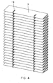
- the combined layers can be pleated into a plurality of longitudinally extending pleats which can be separated by spacer material in such a unique manner that the upstream crests of the pleats are of a selected narrow breadth so that the combined pleated filter arrangement obtains a desired minimum efficiency reporting value (MERV) with an appropriate minimal pressure drop.
- MEV minimum efficiency reporting value
- the present invention provides a unified high efficiency, low pressure drop pleated fluid filter media product including an upstream and downstream face and being capable of obtaining a desirable minimum efficiency reporting value (MERV) comprising: at least one layer of downstream support scrim of a first fibrous material of selected by relative estimation of weight, fiber size and thickness; and, at least one application of fibrous filter media material combined in facing relation on the support scrim, with the combined scrim and filter media layer being pleated into a plurality of longitudinally extending adjacent crested pleats of specified depth and specified spacing between pleats to provide upstream and downstream filter faces, the combined scrim and filter media layer also being selected by relative estimation of weight, fiber size and thickness, and the longitudinally extending pleats of the combined layer being separated by a series of inventively contoured narrow strips of spacer material of specified shape and thickness to determine spacing between pleats with the upstream pleat crests being of selected narrow breadth whereby the combined pleated filter arrangement obtains a desired minimum efficiency reporting value (MERV) at a desired pressure drop
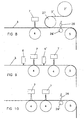
- FIG. 1 and 1A of the drawings discloses structure utilized to carry out one embodiment of the several steps of the inventive method to produce the novel high efficiency low pressure drop pleated fluid filter media - such as air filter media - a supply roll 2, which, if desirable, can be rotated by a suitable controllable motor (not shown) feeds from a supply zone a layer of comparatively selected scrim layer 3 to the anvil roll 4 which serves as a forming zone.
- the selected scrim layer 3 functions as a downstream support layer and, in accordance with one feature of the invention, advantageously can be a dri-laid or spun bond scrim material in the range of approximately forty (40) to one hundred fifty (150) grams per square meter and advantageously around sixty (60) grams per square meter (g./sq. m.) in basic weight with a fiber size of in the range of approximately seven (7) to one hundred (100) micrometers and advantageously around forty five (45) micrometers for the dri-laid and around twenty (20) micrometers in diameter for spun-bond and a Gurley stiffness of in the range of thirty (30) to five hundred (500) grams and advantageously around eighty (80) grams.
- the hot melt spray can selectively be a plastomer material such as polyethylenevinylacetate.
- an application of fine melt blown polypropylene filter media material of a relatively estimated selected weight, fiber size, thickness and porosity is applied in the forming zone 4 from a spinning source 7 to the hot melt sprayed downstream scrim support layer 3.
- the spinning source 7 can advantageously be in accordance with any one or more of the melt blown patented processes heretofore identified in the specification and therefore not described in detail herein.
- the combined scrim and filter media layer 3 is passed along from the forming zone over spaced, aligned turning guide roller 5 to a scoring zone 9 in order to make sharp scores on combined scrim and filter media layer 3 for pleating purposes by providing a series of spaced rows of spaced aligned scores which extend laterally or transversely across the combined scrim and filter media layer 3. The spacing of these rows of lateral, transversely spaced scores is selected to determine the depth of the subsequently formed pleats.
- the pleats can be of a depth of approximately three quarters (3/4) inch.
- the formed scores are empirically or by relative estimation selectively and inventively of very small size to insure that the longitudinally extending upstream crests of subsequently formed pleats are desirably sharp and narrow in breadth so as to afford a minimum of crest resistance to a treated fluid stream.
- the peak sharpness advantageously can be in the range of zero point zero one (0.01) to zero point two (0.2) inches, and, advantageously, the breadth of the crests can be less than zero point zero five (0.05) inches, depending upon the thickness of combined scrim and filter media layer 3.
- the combined scrim and filter media layer 3 is passed along to spacer application zone 17 to turning guide roller 14 and over endless belt conveyor 16. It is to be noted that the guide rollers 5 and 14 are so spaced and positioned that both faces of combined scrim and filter media layer 3 can be accessible to spacer treatment by pleat spacer applicators 17 and 18.
- the high efficiency fluid filter material of the combined scrim and filter media layer 3 has a desired minimum efficiency reporting value (MERV) of at least twelve (12) under ASHRAE standard 52.2 - 1999 at a minimum fluid flow pressure drop of approximately zero point two (0.2) inches of water gage at a fluid flow rate of approximately three hundred (300) feet per minute (ft/min.).
- MMV minimum efficiency reporting value
- the combined scrim and filter media layer 3 is capable of capturing at least eighty (80) percent (%) or more of particle sizes in the range of one (1) to three (3) microns and at least (90) percent (%) of particle sizes in the range of three (3) to ten (10) microns in a treated fluid stream moving at approximately three hundred (300) feet per minute (ft/min) for residential application and at approximately five hundred (500) feet per minute (ft/min) for commercial and industrial applications.
- the pleat spacers in the spacer treating zone can be of varied form - Figures 2, 2A and 4 disclosing spaced lateral rows of inventively cross-sectional bow shaped short spacer strips 19 spacer strips 19 extending in spaced longitudinal alignment along combined scrim and filter media layer 3 and Figure 3 disclosing laterally spaced longitudinally extending spacer strips 21 on combined scrim and filter media layer 3.
- short spacers 19 and continuous longitudinally extending spacers 21 can be formed from any one of a member of known suitable fluid pliable adhesives which can be inserted in aforedescribed spacer applicators 17 and 18.
- the strips can be formed from thermo-bondable plastic materials which can incorporate a small percentage by weight of calcium carbonate, clay, phosphate derivatives or halogenic derivatives to enhance flame retardency and reduce costs with spacing in the range of one (1) to four (4) inches.
- the thickness of the applied spacer materials in accordance with one feature of the present invention can be carefully selected so as to optimize pleat spacing and fluid resistance.
- the adhesive spacers can have an optimum thickness of approximately zero point one (0.1) inches.
- the cross-sectional bow shape is narrowest at the middle area where it is arranged to engage the sharp pleat crest so as to thus optimize pleat spacing and fluid resistance.
- the peak sharpness can be in the range of zero point zero one (0.01) to zero point two (0.2) inches.
- a support scrim 3 of cellulosic material embodying the features of the present invention can be used in a cylindrical type filter application 15 with a typical basic weight being approximately one hundred (100) grams per square meter (g/sq. m.).
- FIG. 6 of the drawings there is schematically disclose in another embodiment of the present invention, a modified upstream forming zone portion of the structure which can be used in the present invention.
- an ultrasonic horn 26 and anvil 26' are disclosed positioned above the upper part of combined scrim and filter media layer 3 in spaced relation downstream from the melt blown spinning source 7.
- the ultrasonic horn 26 can have a frequency in the range of five (5) to sixty (60) kilohertz (kHz) and advantageously twenty (20) kilohertz, serving to heat and adhesively bind the combined scrim and filter media layer 3 before the same is passed to the other zones disclosed in Figures 1 and 1A.
- FIG 7 another forming zone embodiment of the upstream structure is disclosed.
- the upstream melt blown layer is composed of very fine fibers with some loose ends
- at least one upstream scrim is added on top of this layer.
- a second hot melt spray 6' is positioned in spaced relation downstream melt blown spinning arrangement 7 and an upper scrim layer 3' is added from scrim supply source 2', feeding scrim 3' over idle roller 27 before it engages the combined filter media and scrim layer 3.
- scrim 3' can be a synthetic spun bond scrim in the range by weight of approximately five (5) to forty (40) grams per square meter (g/sq.
- the upstream scrim layer 3' can be of a synthetic material such as a low melt polypropylene spun bond material of approximately fourteen (14) grams per square meter (g/sq. m.) as can the other combined filter media application from the melt blown source thus being sandwiched in faced relation between scrim layers 3 and 3'.
- the high efficiency fluid filter material of the combined sandwiched layer 3 of Figure 7, including the filter media application sandwiched between downstream and upstream scrim layers has a desired minimum efficiency reporting value (MERV) of at least twelve (12) under ASHRAE standard 52.2 - 1999 at a minimum fluid flow pressure drop of approximately zero point two (0.2) inches of water gage at a fluid flow rate of approximately three hundred (300) feet per minute (ft/min.).
- MMV minimum efficiency reporting value
- the combined scrim and sandwiched filter media layer is capable of capturing at least eighty (80) percent (%) or more of particle sizes in the range of one (1) to three (3) microns and at least (90) percent (%) of particle sizes in the range of three (3) to ten (10) microns in a treated fluid stream moving at approximately three hundred (300) feet per minute (ft/min) for residential application and at approximately five hundred (500) feet per minute (ft/min) for commercial and industrial applications.
- the downstream support scrim of the combined scrims and filter media application layer of Figure 7 can be a dri-laid or spun bond scrim material in the range of approximately forty (40) to one hundred fifty (150) grams per square meter and advantageously around sixty (60) grams per square meter (g/sq. m) in basic weight with a fiber size in the range of approximately seven (7) to one hundred (100) micrometers and advantageously around forty five (45) micrometers for the dri-laid and around twenty (20) micrometers in diameter for spun-bond and a Gurley stiffness in the range of thirty (30) to five hundred (500) grams and advantageously around eighty (80) grams.
- the aforedescribed sandwiched filter media of Figure 7 can be a fine synthetic material such as a melt blown polypropylene and the upstream scrim can be a light weight synthetic spun bond scrim in the range by weight of approximately five (5) to forty (40) grams per square meter (g/sq. m) and advantageously a polypropylene spun bond scrim of approximately fourteen (14) grams per square meter (g/sq. m).
- the hot melt spray from hot melt sprays 6 and 6' can be a synthetic hot melt adhesive such as a low melt polyethylene or a plastomer such as polyethylenevinylacetate.
- the hot melt spray mechanism 6 can be replaced by an ultrasonic horn 26 and anvil 26' with a horn frequency of five (5) to sixty (60) kilohertz (kHz) and advantageously twenty (20) kilohertz to heat and adhesively bind the scrim and filter media layers.
- an ultrasonic horn 26 and anvil 26' can be spacedly positioned downstream melt blown spinning mechanism spaced and scrim supply 2' and idle roller 27 which serves to add the third lighter scrim layer 3'.
- the forming zone embodiment disclosed includes hot melt sprays 6 and 6' and intermediate spaced melt blown spinning mechanism 7 and anvil 4 and a further second downstream spaced melt blown spinning mechanism 7 and anvil 4.
- the forming zone includes two successively spaced melt blown spinning mechanisms 7 and anvil 4 above the scrim layer 3 which are followed by ultrasonic horn and anvil 26 and 26'.
- the forming zone includes three successively spaced hot melt sprays 6 with intermediate melt blown spinning mechanisms 7 and anvil 4. This arrangement is followed by a spaced light weight scrim third layer supply 2' and accompanying idle roller 27.
- a still further forming embodiment of invention which includes above the combined scrim and filter media layer 3, two spaced melt blown spinning mechanisms 7 and anvils 4 followed by a light weight scrim supply 2' and accompanying idle roller 27 followed by spaced ultrasonic horn 26 and anvil 26'.
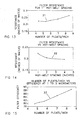
- curve 31 is disclosed sloping upwardly from left to right with the resistance increasing as the number of pleats per inch increases.
- curve 32 is disclosed sloping downwardly from left to right with the resistance decreasing as the hot melt spacing decreases.
- the novel method includes the steps of feeding from a supply zone to a spaced filter media application zone at least one layer of support scrim material of empirically or relatively estimated and selected weight, fiber size and thickness; applying and combining at least one application of filter media on the support scrim, such filter media also being of empirically or relatively estimated selected weight, fiber size and thickness so as to obtain at least a combination of scrim and filter media of desired minimum efficiency reporting value (MERV) at a desired pressure drop.
- MMV minimum efficiency reporting value
- the combined layer of scrim and filter media application(s) can be moved to still another scrim applicator zone to apply a comparatively light weight scrim layer obtaining sandwiched filter media and scrim combination.
- Appropriate hot melt adhesive spraying zones or ultrasound treating zones can be utilized in forming two, three or even more filter media applications.
- Further steps can be included wherein the applied filter media is successively passed to a hot melt spacing zone; at least one spacer applicator zone and advantageously to two such spacer application zones to apply spacers in a spaced selected shaped segment or continuous longitudinally ribbon form on opposite faces of the combined scrim and filter media layer with the combined layer then being passed to a successive pleating zone 4.
- test results 1 with spun-bond support scrim Test Air Flow Rate (CFM)/Velocity (FPM) 819 cfm/295fpm Initial Resistance (in. WG) 0.196 Final Resistance (in.
- WG 1.0 Minimum Efficiency Rating Value (MERV) MERV 12 @820 cfm Minimum Average Efficiency 0.3 to 1.0 Microns (E1) 52.2 Minimum Average Efficiency 1.0 to 3.0 Microns (E2) 81.4 Minimum Average Efficiency 3.0 to 10.0 Microns (E3) 96.6 Dust Fed to Final Resistance (grams) 17.2 grams Test Results 2 with dri-laid support scrim: Test Air Flow Rate (CFM)/Velocity (FPM) 819 cfm/295fpm Initial Resistance (in. WG) 0.183 Final Resistance (in.
- CFM Test Air Flow Rate
- FPM Velocity
- WG 1.0 Minimum Efficiency Rating Value (MERV) MERV 12 @819 cfm Minimum Average Efficiency 0.3 to 1.0 Microns (E1) 61.1 Minimum Average Efficiency 1.0 to 3.0 Microns (E2) 86.9 Minimum Average Efficiency 3.0 to 10.0 Microns (E3) 97.8 Dust Fed to Final Resistance (grams) 13.0 grams
Landscapes
- Chemical & Material Sciences (AREA)
- Chemical Kinetics & Catalysis (AREA)
- Physics & Mathematics (AREA)
- Geometry (AREA)
- Filtering Materials (AREA)
Applications Claiming Priority (2)
| Application Number | Priority Date | Filing Date | Title |
|---|---|---|---|
| US317437 | 1994-10-04 | ||
| US10/317,437 US7097684B2 (en) | 2002-12-12 | 2002-12-12 | Method of forming combined pleated scrim and filter media materials and product of same |
Publications (1)
| Publication Number | Publication Date |
|---|---|
| EP1428566A1 true EP1428566A1 (fr) | 2004-06-16 |
Family
ID=32325941
Family Applications (1)
| Application Number | Title | Priority Date | Filing Date |
|---|---|---|---|
| EP03078819A Withdrawn EP1428566A1 (fr) | 2002-12-12 | 2003-12-03 | Procédé de fabrication de gaze et de matériaux filtrants pliés combinés et produit obtenu par ce procédé |
Country Status (3)
| Country | Link |
|---|---|
| US (1) | US7097684B2 (fr) |
| EP (1) | EP1428566A1 (fr) |
| CA (1) | CA2435470A1 (fr) |
Cited By (6)
| Publication number | Priority date | Publication date | Assignee | Title |
|---|---|---|---|---|
| WO2008068182A1 (fr) * | 2006-12-04 | 2008-06-12 | Mann+Hummel Gmbh | Garniture de filtre remplaçable |
| EP1860236A3 (fr) * | 2006-05-24 | 2008-10-15 | Johns Manville | Tapis à fibres non tissées pour filtre MERV et procédé de fabrication |
| EP2188031A1 (fr) * | 2007-09-07 | 2010-05-26 | E. I. du Pont de Nemours and Company | Structures plissées en nanotissu améliorées |
| EP2714240A4 (fr) * | 2011-05-27 | 2015-06-03 | Clarcor Air Filtration Products Inc | Batterie de filtres non en v pour une installation de confinement d'animaux |
| US9687766B2 (en) | 2011-05-27 | 2017-06-27 | Clarcor Air Filtration Products, Inc. | Collapsible and/or assembled filter housing and filter used therewith |
| CN120502141A (zh) * | 2025-05-28 | 2025-08-19 | 江西虔悦新材料有限公司 | 基于钴镍负载的石墨烯吸波材料制备方法 |
Families Citing this family (32)
| Publication number | Priority date | Publication date | Assignee | Title |
|---|---|---|---|---|
| US20060027494A1 (en) * | 1999-01-23 | 2006-02-09 | Aaf-Mcquay, Inc., A Kentucky Corporation | Oil treated filter media |
| US20040261376A1 (en) * | 2003-06-26 | 2004-12-30 | Morgan Lee Pendleton | Pleated air filter with reverse pulsating air flow cleaning |
| US7896940B2 (en) * | 2004-07-09 | 2011-03-01 | 3M Innovative Properties Company | Self-supporting pleated filter media |
| US7156891B2 (en) * | 2004-09-10 | 2007-01-02 | Filtration Group Incorporated | Forced air system air filter |
| US20060137317A1 (en) * | 2004-12-28 | 2006-06-29 | Bryner Michael A | Filtration media for filtering particulate material from gas streams |
| US7625418B1 (en) * | 2005-06-08 | 2009-12-01 | Aaf-Mcquay, Inc. | Spacer arrangement for pleated filter |
| US7481862B2 (en) * | 2005-06-09 | 2009-01-27 | Purolator Filters Na Llc | Filter assembly using adhesive center tube |
| DE102006047316A1 (de) * | 2006-10-06 | 2008-04-10 | Pfannenberg Gmbh | Filterlüfter |
| US8986432B2 (en) * | 2007-11-09 | 2015-03-24 | Hollingsworth & Vose Company | Meltblown filter medium, related applications and uses |
| CN107126764A (zh) * | 2007-11-09 | 2017-09-05 | 霍林斯沃思和沃斯有限公司 | 熔喷过滤介质 |
| US8950587B2 (en) * | 2009-04-03 | 2015-02-10 | Hollingsworth & Vose Company | Filter media suitable for hydraulic applications |
| CN102458608B (zh) * | 2009-06-12 | 2016-08-31 | 克拉克空气过滤产品有限公司 | 无薄膜过滤器和/或用于过滤器的整体框架 |
| US10065481B2 (en) * | 2009-08-14 | 2018-09-04 | Freudenberg Filtration Technologies, L.P. | Non-woven air exhauster and filter |
| US8679218B2 (en) | 2010-04-27 | 2014-03-25 | Hollingsworth & Vose Company | Filter media with a multi-layer structure |
| CN103180887B (zh) | 2010-07-22 | 2016-11-09 | 克拉克空气过滤产品有限公司 | 结合有防水过滤器的自助式服务终端机 |
| US10155186B2 (en) | 2010-12-17 | 2018-12-18 | Hollingsworth & Vose Company | Fine fiber filter media and processes |
| US20120152821A1 (en) | 2010-12-17 | 2012-06-21 | Hollingsworth & Vose Company | Fine fiber filter media and processes |
| DE102011050915A1 (de) * | 2011-06-08 | 2012-12-13 | Neufilter Gmbh | Papiergelegefiltermodul, Verfahren zur Herstellung eines solchen Papiergelegefiltermoduls und Papiergelegefiltermodulwand aus einer Mehrzahl derartiger Papiergelegefiltermodule |
| EP2966197A4 (fr) * | 2013-03-08 | 2017-03-08 | Finetex Ene, Inc. | Appareil d'électrofilage |
| MX386355B (es) | 2013-03-15 | 2025-03-18 | Donaldson Co Inc | Medios y elementos de filtro. |
| US9694306B2 (en) | 2013-05-24 | 2017-07-04 | Hollingsworth & Vose Company | Filter media including polymer compositions and blends |
| US9474994B2 (en) | 2013-06-17 | 2016-10-25 | Donaldson Company, Inc. | Filter media and elements |
| EP3077078A1 (fr) * | 2013-12-05 | 2016-10-12 | Mann+Hummel GmbH | Élément de filtrage avec soufflet de filtrage |
| US10730001B2 (en) * | 2014-09-08 | 2020-08-04 | Clarcor Air Filtration Products, Inc. | Filter with high dust capacity |
| US10343095B2 (en) | 2014-12-19 | 2019-07-09 | Hollingsworth & Vose Company | Filter media comprising a pre-filter layer |
| DE102015006355A1 (de) * | 2015-05-19 | 2016-11-24 | Mann + Hummel Gmbh | Filterelement mit Filterbalg |
| JP6674823B2 (ja) * | 2016-04-01 | 2020-04-01 | 株式会社テクノフロンティア | 筒状フィルタ |
| JP6715653B2 (ja) * | 2016-04-01 | 2020-07-01 | 株式会社テクノフロンティア | 筒状フィルタ |
| US12420221B2 (en) | 2016-07-01 | 2025-09-23 | Hollingsworth & Vose Company | Multi-layered electret-containing filtration media |
| JP2019531880A (ja) * | 2016-08-26 | 2019-11-07 | スリーエム イノベイティブ プロパティズ カンパニー | 縁部ダムを有するプリーツフィルタメディアを備えるプリーツフィルタエレメント並びにこれを製造及び使用する方法 |
| US11123946B2 (en) * | 2019-02-07 | 2021-09-21 | K&N Engineering, Inc. | Pleated filter preparation system |
| US11638893B1 (en) * | 2022-12-29 | 2023-05-02 | Filtration Advice, Inc. | Reinforced air filter |
Citations (3)
| Publication number | Priority date | Publication date | Assignee | Title |
|---|---|---|---|---|
| US5084178A (en) * | 1988-06-15 | 1992-01-28 | Pall Corporation | Corrugated filter arrangement with support layer and flow channels |
| US5800586A (en) * | 1996-11-08 | 1998-09-01 | Johns Manville International, Inc. | Composite filter media |
| US6165242A (en) * | 1999-03-27 | 2000-12-26 | Aaf International, Inc | Pleated filter media with crest spacers and method of making |
Family Cites Families (17)
| Publication number | Priority date | Publication date | Assignee | Title |
|---|---|---|---|---|
| US4917942A (en) * | 1988-12-22 | 1990-04-17 | Minnesota Mining And Manufacturing Company | Nonwoven filter material |
| ATE98892T1 (de) | 1989-01-05 | 1994-01-15 | Camfil Ab | Filter. |
| DE3916838A1 (de) * | 1989-05-19 | 1990-11-22 | Lippold Hans Joachim | Filtereinsatz |
| DE4004079A1 (de) * | 1990-02-08 | 1991-08-14 | Lippold Hans Joachim | Filtereinsatz |
| US5306321A (en) | 1992-07-07 | 1994-04-26 | Donaldson Company, Inc. | Layered air filter medium having improved efficiency and pleatability |
| US5427597A (en) * | 1992-07-07 | 1995-06-27 | Donaldson Company, Inc. | Layered air filter medium having improved efficiency and pleatability |
| DE4345122A1 (de) | 1993-12-30 | 1995-07-06 | Detroit Holding Ltd | Verfahren zur Herstellung eines Filtereinsatzes |
| US6146436A (en) * | 1994-08-05 | 2000-11-14 | Firma Carl Freudenberg | Cartridge filter |
| US5891482A (en) | 1996-07-08 | 1999-04-06 | Aaf International | Melt blowing apparatus for producing a layered filter media web product |
| US5725812A (en) | 1996-07-08 | 1998-03-10 | Aaf International | Melt blowing apparatus and method for forming a fibrous layered web of filter media including a fluid distribution arrangement |
| US7625420B1 (en) * | 1997-02-24 | 2009-12-01 | Cabot Corporation | Copper powders methods for producing powders and devices fabricated from same |
| US5968373A (en) | 1997-12-22 | 1999-10-19 | Aaf International | Filter arrangement having at least two successive layers having predetermined spacing and its method for making |
| US6159318A (en) | 1998-10-21 | 2000-12-12 | Aaf International, Inc. | Method for forming fibrous filter media, filter units and product |
| US6165241A (en) * | 1999-03-27 | 2000-12-26 | Aaf International, Inc. | Pleated filter media with strip spacers and method of making |
| US6254653B1 (en) | 1999-10-08 | 2001-07-03 | Aaf International | Pleated fluid filter medium blend |
| US6800117B2 (en) * | 2000-09-05 | 2004-10-05 | Donaldson Company, Inc. | Filtration arrangement utilizing pleated construction and method |
| EP1339477A4 (fr) * | 2000-11-14 | 2007-07-04 | Lydall Inc | Materiau de filtration de gaz forme par voie seche/humide |
-
2002
- 2002-12-12 US US10/317,437 patent/US7097684B2/en not_active Expired - Fee Related
-
2003
- 2003-07-17 CA CA002435470A patent/CA2435470A1/fr not_active Abandoned
- 2003-12-03 EP EP03078819A patent/EP1428566A1/fr not_active Withdrawn
Patent Citations (3)
| Publication number | Priority date | Publication date | Assignee | Title |
|---|---|---|---|---|
| US5084178A (en) * | 1988-06-15 | 1992-01-28 | Pall Corporation | Corrugated filter arrangement with support layer and flow channels |
| US5800586A (en) * | 1996-11-08 | 1998-09-01 | Johns Manville International, Inc. | Composite filter media |
| US6165242A (en) * | 1999-03-27 | 2000-12-26 | Aaf International, Inc | Pleated filter media with crest spacers and method of making |
Cited By (10)
| Publication number | Priority date | Publication date | Assignee | Title |
|---|---|---|---|---|
| EP1860236A3 (fr) * | 2006-05-24 | 2008-10-15 | Johns Manville | Tapis à fibres non tissées pour filtre MERV et procédé de fabrication |
| WO2008068182A1 (fr) * | 2006-12-04 | 2008-06-12 | Mann+Hummel Gmbh | Garniture de filtre remplaçable |
| US8501002B2 (en) | 2006-12-04 | 2013-08-06 | Mann + Hummel Gmbh | Exchangeable filter insert |
| EP2188031A1 (fr) * | 2007-09-07 | 2010-05-26 | E. I. du Pont de Nemours and Company | Structures plissées en nanotissu améliorées |
| EP2714240A4 (fr) * | 2011-05-27 | 2015-06-03 | Clarcor Air Filtration Products Inc | Batterie de filtres non en v pour une installation de confinement d'animaux |
| US9185877B2 (en) | 2011-05-27 | 2015-11-17 | Clarcor Air Filtration Products, Inc. | Collapsible and/or assembled filter housing and filter used therewith |
| US9510557B2 (en) | 2011-05-27 | 2016-12-06 | Clarcor Air Filtration Products, Inc. | Non V-bank filter for animal confinement facility |
| US9687766B2 (en) | 2011-05-27 | 2017-06-27 | Clarcor Air Filtration Products, Inc. | Collapsible and/or assembled filter housing and filter used therewith |
| US10507416B2 (en) | 2011-05-27 | 2019-12-17 | Clarcor Air Filtration Products, Inc. | Inlet frame and filter assembly including an inlet frame |
| CN120502141A (zh) * | 2025-05-28 | 2025-08-19 | 江西虔悦新材料有限公司 | 基于钴镍负载的石墨烯吸波材料制备方法 |
Also Published As
| Publication number | Publication date |
|---|---|
| CA2435470A1 (fr) | 2004-06-12 |
| US20040112023A1 (en) | 2004-06-17 |
| US7097684B2 (en) | 2006-08-29 |
Similar Documents
| Publication | Publication Date | Title |
|---|---|---|
| US7097684B2 (en) | Method of forming combined pleated scrim and filter media materials and product of same | |
| US7661540B2 (en) | Method of forming spaced pleated filter material and product of same | |
| CA2572307C (fr) | Procede de formation de supports filtrants plisses autoporteurs | |
| US7896940B2 (en) | Self-supporting pleated filter media | |
| US7625418B1 (en) | Spacer arrangement for pleated filter | |
| US6409864B1 (en) | Method of assembly of pleated filter with spacer insert | |
| US8152889B2 (en) | Filter with EPTFE and method of forming | |
| CA2311138C (fr) | Melange de materiau filtrant pour liquides et methode de fabrication | |
| US7112255B2 (en) | Thermobondable filter medium and border frame and method of making same | |
| US6165241A (en) | Pleated filter media with strip spacers and method of making | |
| US6165242A (en) | Pleated filter media with crest spacers and method of making | |
| US12017175B2 (en) | Pleated air filter with bridging filaments and continuous-contact filaments | |
| CA3108368A1 (fr) | Filtre a air plisse avec filaments de renforcement comprenant des zones de flexion localement amincies | |
| US12076680B1 (en) | Air filter with different diameter glue beads | |
| CN1354082A (zh) | 蜂窝制造方法 | |
| WO2007047636A1 (fr) | Filtre à panneau et processus de fabrication de filtre à panneau |
Legal Events
| Date | Code | Title | Description |
|---|---|---|---|
| PUAI | Public reference made under article 153(3) epc to a published international application that has entered the european phase |
Free format text: ORIGINAL CODE: 0009012 |
|
| AK | Designated contracting states |
Kind code of ref document: A1 Designated state(s): AT BE BG CH CY CZ DE DK EE ES FI FR GB GR HU IE IT LI LU MC NL PT RO SE SI SK TR |
|
| AX | Request for extension of the european patent |
Extension state: AL LT LV MK |
|
| 17P | Request for examination filed |
Effective date: 20041216 |
|
| AKX | Designation fees paid |
Designated state(s): AT BE BG CH CY CZ DE DK EE ES FI FR GB GR HU IE IT LI LU MC NL PT RO SE SI SK TR |
|
| 17Q | First examination report despatched |
Effective date: 20100120 |
|
| STAA | Information on the status of an ep patent application or granted ep patent |
Free format text: STATUS: THE APPLICATION IS DEEMED TO BE WITHDRAWN |
|
| 18D | Application deemed to be withdrawn |
Effective date: 20110701 |