EP1428596A1 - Installation pour la fabrication de grilles en fils de fer - Google Patents
Installation pour la fabrication de grilles en fils de fer Download PDFInfo
- Publication number
- EP1428596A1 EP1428596A1 EP02406080A EP02406080A EP1428596A1 EP 1428596 A1 EP1428596 A1 EP 1428596A1 EP 02406080 A EP02406080 A EP 02406080A EP 02406080 A EP02406080 A EP 02406080A EP 1428596 A1 EP1428596 A1 EP 1428596A1
- Authority
- EP
- European Patent Office
- Prior art keywords
- cross
- combing
- assembly unit
- conveyor belt
- wires
- Prior art date
- Legal status (The legal status is an assumption and is not a legal conclusion. Google has not performed a legal analysis and makes no representation as to the accuracy of the status listed.)
- Withdrawn
Links
- 238000003466 welding Methods 0.000 claims description 41
- 238000006073 displacement reaction Methods 0.000 claims description 21
- 238000002360 preparation method Methods 0.000 claims description 19
- 238000005259 measurement Methods 0.000 claims description 7
- 230000006698 induction Effects 0.000 claims description 4
- 210000001520 comb Anatomy 0.000 claims description 3
- 230000002093 peripheral effect Effects 0.000 description 9
- 238000004519 manufacturing process Methods 0.000 description 4
- 230000006978 adaptation Effects 0.000 description 3
- 230000001360 synchronised effect Effects 0.000 description 3
- 230000005540 biological transmission Effects 0.000 description 2
- 230000005484 gravity Effects 0.000 description 2
- 239000010410 layer Substances 0.000 description 2
- 229910000746 Structural steel Inorganic materials 0.000 description 1
- 238000010276 construction Methods 0.000 description 1
- 238000011109 contamination Methods 0.000 description 1
- 230000001419 dependent effect Effects 0.000 description 1
- 230000001771 impaired effect Effects 0.000 description 1
- 238000002955 isolation Methods 0.000 description 1
- 238000000034 method Methods 0.000 description 1
- 230000010363 phase shift Effects 0.000 description 1
- 238000009420 retrofitting Methods 0.000 description 1
- 238000000926 separation method Methods 0.000 description 1
- 239000002356 single layer Substances 0.000 description 1
- 238000003860 storage Methods 0.000 description 1
Images


Classifications
-
- B—PERFORMING OPERATIONS; TRANSPORTING
- B21—MECHANICAL METAL-WORKING WITHOUT ESSENTIALLY REMOVING MATERIAL; PUNCHING METAL
- B21F—WORKING OR PROCESSING OF METAL WIRE
- B21F27/00—Making wire network, i.e. wire nets
- B21F27/08—Making wire network, i.e. wire nets with additional connecting elements or material at crossings
- B21F27/10—Making wire network, i.e. wire nets with additional connecting elements or material at crossings with soldered or welded crossings
-
- B—PERFORMING OPERATIONS; TRANSPORTING
- B21—MECHANICAL METAL-WORKING WITHOUT ESSENTIALLY REMOVING MATERIAL; PUNCHING METAL
- B21F—WORKING OR PROCESSING OF METAL WIRE
- B21F23/00—Feeding wire in wire-working machines or apparatus
- B21F23/005—Feeding discrete lengths of wire or rod
-
- B—PERFORMING OPERATIONS; TRANSPORTING
- B65—CONVEYING; PACKING; STORING; HANDLING THIN OR FILAMENTARY MATERIAL
- B65G—TRANSPORT OR STORAGE DEVICES, e.g. CONVEYORS FOR LOADING OR TIPPING, SHOP CONVEYOR SYSTEMS OR PNEUMATIC TUBE CONVEYORS
- B65G47/00—Article or material-handling devices associated with conveyors; Methods employing such devices
- B65G47/02—Devices for feeding articles or materials to conveyors
- B65G47/04—Devices for feeding articles or materials to conveyors for feeding articles
- B65G47/12—Devices for feeding articles or materials to conveyors for feeding articles from disorderly-arranged article piles or from loose assemblages of articles
- B65G47/14—Devices for feeding articles or materials to conveyors for feeding articles from disorderly-arranged article piles or from loose assemblages of articles arranging or orientating the articles by mechanical or pneumatic means during feeding
- B65G47/1407—Devices for feeding articles or materials to conveyors for feeding articles from disorderly-arranged article piles or from loose assemblages of articles arranging or orientating the articles by mechanical or pneumatic means during feeding the articles being fed from a container, e.g. a bowl
Definitions
- the invention relates to a system for producing wire mesh from intersecting and at the crossing points welded longitudinal and transverse wires.
- Grid welding systems known hitherto for producing wire grids of the type mentioned at the beginning Type such as Structural steel mats, lattice structures of shopping trolleys, storage racks etc. enable the production of wire mesh with a high production rate, as long as all cross wires are essentially identical to each other are.
- cross wires with different Diameters and / or different lengths are to be processed Time-consuming and complicated retrofitting work required to the grid welding machine to adapt to the changed cross wire dimensions.
- the object of the invention is to provide a grid welding system which is quick and simple adaptation of the mesh welding system for processing cross wires with modified Cross wire dimensions enabled.
- the solution to the problem is defined by the features of claim 1.
- the Invention has a mesh welding system for producing wire mesh from each other intersecting longitudinal and transverse wires welded together at the crossing points at least one welding machine for welding a cross wire a plurality of longitudinal wires and a cross wire feeder for feeding of the cross wire to the welding machine.
- the cross wire feeder includes a cross wire preparation device, which is used for the bundle pickup of cross wires, for separating the cross wires and for providing the separated cross wires one after the other in a one defined by the cross wire provision device Provision position is formed.
- the cross wire provision device has a stationary machine frame as well as at least a first conveyor belt for conveying the isolated cross wires are formed with respect to the machine frame and defines a feed direction.
- the first conveyor belt is part of a first assembly unit formed, which is displaceable as a whole transversely to the feed direction.
- the cross wire delivery facility also has first displacement means for displacing the first assembly unit transverse to the feed direction.
- the direction of transport of the cross wire from the place its inclusion by the feed device up to the welding machine as the feed direction designated.
- the feed direction usually changes during transport of the cross wire through the feed device. It depends on the location of the cross wire in the Feeder from. Corresponds in the area of the conveyor belt for cross wire transport the feeding direction of the conveying direction of the cross wire on the conveyor belt.
- first assembly unit and the cross wire preparation device provided with first displacement means for displacing the first assembly unit is a simple and quick adjustment of the position of the first conveyor belt enabled across the conveying direction. This enables the cross wire provision device can be quickly and easily adapted to different lengths of cross wires on the first conveyor belt are conveyed transversely to their longitudinal direction.
- the Cluer wire provision device further at least a second to promote the isolated cross wires formed conveyor belt, which is designed as part of a second assembly unit, which can be moved as a whole transversely to the feed direction and parallel to the first assembly unit is, and second displacement means for displacing the second assembly unit transversely to the feed direction and parallel to the first assembly unit.
- the at least two across Conveyor belts adjustable in the feed direction allow both an adjustment of the Cross wire supply device to different cross wire lengths as well as one Change of the staging position in which the cross wires are stowed in Regarding the cross wire longitudinal direction.
- the first and second displacement means can be designed such that they are completely mutually independent displacement of the first and second assembly unit guarantee.
- the first and second displacement means can also be designed such that the first and second assembly units are only partially can be moved independently of one another. You can e.g. be trained that the first and second assembly unit only one after the other in two mutually independent Moving positions are displaceable or with a simultaneous shift can only be moved parallel to each other at the same speed are.
- the first and second displacement means a common Threaded spindle, which are parallel to the direction of displacement of the first and extends second assembly units and provided with an external thread and for Moving both the first and the second assembly unit is formed.
- a common threaded spindle to move the first and the second assembly unit allows a particularly simple and inexpensive construction the displacement means.
- there are also other suitable means of moving of the assembly units can be used, e.g. Linear drives based on toothed belts, Circulating chains or pinion racks.
- the first Moving means have a first lock nut that with the first assembly unit is connected and has an internal thread that optionally with the threaded spindle in Can be brought in and brought out of engagement again in order to rotate the threaded spindle the first assembly unit either crosswise in the manner of a spindle-nut drive to move to the feed direction or rest with respect to the stationary machine frame allow.
- the second displacement means can have a second lock nut, which is connected to the second assembly unit and has an internal thread that can optionally be brought into engagement with the threaded spindle and brought out of engagement again is to either the second assembly unit (17, 19) with rotating threaded spindle either to move in the manner of a spindle-nut drive transversely to the feed direction or to let it rest.
- the two lock nuts are preferably independent of one another can be actuated in order to move the to enable both assembly units.
- Assembly units provided a conveyor belt drive shaft in the stationary machine frame rotatable about a first axis of rotation extending transversely to the feed direction and is immovably mounted in the longitudinal direction of the shaft, this conveyor belt drive shaft for driving both the first conveyor belt with respect to the first assembly unit as well as the second conveyor belt with respect to the second assembly unit is.
- This makes it easy to synchronize the conveyor belts of the two Assembly units are guaranteed.
- the movability of the assembly units not to be affected, the conveyor belt drive shaft is non-rotatable, but in Wavelength direction slidably coupled to the assembly units.
- a further drive shaft is advantageously provided, which is in the stationary machine frame rotatable about a second axis of rotation parallel to the first axis of rotation and in the longitudinal direction of the shaft is immovably mounted, this further drive shaft for driving both a first functional unit related to the first assembly unit is rotatable, as well as a second functional unit, which is related to the second assembly unit is rotatable, is formed.
- additional functional units can be installed on the different assembly units are driven synchronously.
- the drive shaft is in turn non-rotatable, but can also be displaced in the longitudinal direction of the shaft coupled to the assembly units to adjust the displaceability of the assembly units to ensure the stationary machine frame.
- a functional unit driven by the further drive shaft can e.g. one with grooving grooves (also known as drive grooves) provided combing wheel (also as Driver wheel or drive plate), which is rotatable about an axis of rotation arranged on a mounting unit and for combing out a single transverse wire a plurality of cross wires is formed.
- Combing wheels are known per se Devices used for separating wires from a wire bundle.
- a functional unit driven by the further drive shaft can also have a support wheel be rotatable about an axis of rotation on a mounting unit and for support a particularly long transverse wire is formed.
- the jockey wheel can in particular arranged parallel to a combing wheel and driven synchronously with it to support the cross wire during combing out.
- Another advantageous variant of the invention is characterized in that the Mounting unit a guide plate is fixedly attached to the lateral guidance of the Cross wires during the conveyance of the cross wires on the same assembly unit arranged conveyor belt is formed and arranged. This enables the guide shield easy to move together with the assembly unit when the Guide plate adjusted for the purpose of adaptation to a changed cross wire length must become.
- the cross wire provision device comprises further a position measuring device and a control device.
- the position measuring device is for automatically measuring the position of all assembly units related to the stationary machine frame, for production of position signals corresponding to the measured positions and for the transmission of these Position signals formed on the control device.
- the control device is dependent on receiving the position signals and generating control signals the position signals and for transmitting the control signals to the displacement means educated.
- the shifting means in turn are for shifting the assembly units depending on the control signals received by the control device educated. This will automatically shift the assembly units to Adaptation of the cross wire provision device to changed cross wire dimensions allows.
- the position measuring device is preferably for measuring the positions of the assembly units based on induction resistance measurements.
- Position measurement sensors on the basis of induction resistance measurements are little interference and susceptible to contamination and therefore good for use in the harsh environment of Suitable for welding machines.
- the cross wire preparation device 10 shown in FIGS. 1 and 2 is part of a grid welding system for the production of wire grids from crossing and at the Crossing points of welded longitudinal and cross wires 1.
- the grid welding system has a welding machine (not shown) for welding a Cross wire 1 with a plurality of longitudinal wires and a cross wire feed device for receiving the cross wire 1 and for feeding the cross wire 1 to the Welding machine on.
- the cross wire feeder includes those in Figs. 1 and 2 shown cross wire supply device 10. This is used for bundle recording of cross wires 1, for separating the cross wires 1 and for providing the isolated cross wires 1 in succession in a through the cross wire supply device 10 defined staging position.
- the cross wire feeder includes further a cross wire transport device (not shown), which the isolated Cross wires 1 are picked up one after the other in the ready position and from the ready position in a predetermined cross wire target position in the welding machine transported.
- a loose bundle of a large number of cross wires is used to operate the grid welding system 1 loaded onto a platform 2 of the cross wire provision device 10, which on a stationary machine frame 3 of the cross wire preparation device 10 is arranged is.
- the top of the platform 2 is designed in the manner of an inclined plane and arranged. It serves as a support or feed surface for the cross wires 1.
- Die Cross wires 1 are with their longitudinal direction transverse to the falling lines of the inclined feed surface (and thus horizontally) aligned so that it is transverse to gravity their longitudinal direction on the feed surface along the fold lines downwards (i.e. in the feed direction) roll or slide.
- a rejection element 4 also as a wiping element referred to
- the height of this control gap is dimensioned such that the cross wires 1 the control gap only as a single-layer wire layer can happen with little play. Cross wires 1 on the lowest cross wire layer are rejected by the rejection body 4.
- the cross wire preparation device 10 further comprises a number of combing-out wheels 5, 6, 1 of which are shown in the illustration in FIG. 1.
- the combing wheels 5, 6 are essentially identical to each other and in relation to the feed direction immediately in front of the control gap parallel to each other around a common (virtual) Rotation axis 11 rotatably arranged.
- the common as Auskmmrad axis of rotation 11
- the axis of rotation 11 of the combing-out wheels 5, 6 runs parallel to the plane of the feed surface and perpendicular to the fall lines of this plane (i.e. overall parallel to the longitudinal direction of the cross wire and therefore horizontal).
- the combing-out wheels 5, 6 essentially have one circumferential surface in the shape of a cylindrical cylinder and are in this way about the (virtual) axis of rotation 11 rotatable that the axis of rotation 11 with the (geometric) cylinder axis of the peripheral surface matches.
- the combing-out wheels 5, 6 are arranged with respect to the feed surface in such a way that the front edge of the inclined feed surface with little in relation to the feed direction Game clearance immediately behind a substantially vertical section of the peripheral surfaces the combing wheels 5, 6.
- the combing wheels 5, 6 are at regular tangential intervals each have mutually identical grooves 12 (combing grooves), which are extend parallel to the combing wheel axis of rotation 11.
- the combing wheels 5, 6 rotate continuously in synchronism with each other the combing wheel axis of rotation 11, the combing wheels 5, 6 being synchronized with one another in this way are mutually corresponding combing grooves 12 of the different combing wheels 5, 6 a series (corresponding to the number of combing wheels 5, 6) of combing grooves Form 12, which are parallel to each other in the Auskalmmrad axis of rotation 11 aligned.
- the direction of rotation of the combing wheels 5, 6 is such that the immediately before portions of the peripheral surfaces of the combing-out wheels lying at the front edge of the feed surfaces 5, 6 run up. This causes everyone to gravity on the feed surface forward and down conveyed cross wire 1 immediately after Pass the control gap individually into one of the series of aligned ones Auskammnuten 12 is promoted.
- the thickness of the combing grooves 12 is the diameter of the cross wires 1 are adjusted in such a way that only one cross wire 1 is recorded.
- the transverse wires 1 received in the combing grooves 12 are taken up by the rotating combing wheels 5, 6 and on a circular Path corresponding to the radial distance of the combing grooves 12 to the combing wheel axis of rotation 11 promoted away from the feed surface.
- the combing wheels 5, 6 cause the actual separation of the cross wires 1, because the previously adjacent cross wires 1 are now individually arranged in the combing-out groove series 12 of the combing-out wheels 5, 6, the comb-out groove series 12 in the peripheral surfaces of the comb-out wheels 5, 6 in tangential direction are spaced from each other.
- the cross wire preparation device 10 is also provided with a plurality of conveyor belts 7, 8, 9 provided, of which three are shown in the illustration of FIG. 1. Every conveyor belt 7, 8, 9 is designed in the manner of an endlessly rotating conveyor belt, the upper one Run the cross bars 1 from the combing wheels during operation of the grid welding system and conveys the feed surface forward and down.
- the conveyor belts 7, 8, 9 are each identical to one another and in relation to the direction of the combing wheel axis of rotation 11 arranged parallel to each other. They run during operation Conveyor belts 7, 8, 9 each in a perpendicular to the combing wheel axis of rotation 11 (and thus vertical) level endlessly.
- Each conveyor belt 7, 8, 9 is on its outside outwardly projecting cams, the term "outside" in the present Connection in relation to the direction of rotation of the conveyor belt 7, 8, 9 to understand is.
- the cams are at regular intervals along the entire length of the belt distributed.
- all conveyor belts 7, 8, 9 run synchronously to each other, the conveyor belts 7, 8, 9 being synchronized to one another in such a way that corresponding cams of the different conveyor belts 7, 8, 9 each a series (corresponding to the number of conveyor belts) of cams that are related to the Direction of the combing wheel axis of rotation 11 are arranged parallel to each other.
- a transport compartment is defined between two adjacent cam series, which for Includes a cross wire 1.
- Each of the grooves 12 in the combing-out wheels 5, 6 recorded cross wires 1 is by the rotating combing wheels 5, 6 on a circular path from the feed surface to the conveyor belts 7, 8, 9 and conveyed stored there individually in a transport compartment, the length of the transport route Cross wires 1 from the feed surface to the conveyor belts about a third of that circular path corresponding circular circumference.
- cross wires 1 After the cross wires are placed individually in the transport compartments, they are through the upper run of the conveyor belts 7, 8, 9 in a feed direction defined by this run conveyed diagonally forwards and downwards.
- the cross wires 1 In the area of the conveyor belt drive rollers 13, which is also formed as the foremost deflection roller of each conveyor belt 7, 8, 9 are, the cross wires 1 in succession in a stationary cross wire holder 14th the cross wire supply device filed or discarded.
- This cross wire holder 14 comprises a plurality of identically designed plate-shaped holding parts, in whose top is each formed a V-shaped groove. The holding parts are arranged in such a way that their V-shaped grooves in the direction parallel to the combing wheel axis of rotation 11 to each other aligned.
- the cross wire holder 14 By the cross wire holder 14, the ready position Cross wires 1 defined in relation to the directions perpendicular to the longitudinal direction of the cross wire.
- the position of the cross wires 1 in the longitudinal direction of the cross wire (and thus the ready position of the cross wires in relation to the cross wire longitudinal direction) is first through two vertical guide plates 15 roughly defined in relation to the feed direction laterally next to the two outermost conveyor belts 9 of the cross wire preparation device are arranged.
- These guide plates 15 are in relation to the feed direction slightly tapered from the back to the front and work during the transport of the cross wires 1 on the conveyor belts 7, 8, 9 in abrupt Function on the facing longitudinal end of each cross wire 1.
- each cross wire 1 during transport on the conveyor belts 7, 8, 9 through the Guide plates 15 from its two longitudinal ends in the cross wire longitudinal direction in the desired longitudinal position pushed before being dropped into the cross wire holder 14 becomes.
- the cross wire preparation device 14 is further provided with two plungers 16, arranged in the extension of the mutually aligned grooves of the cross wire holder 14 are and in the cross wire longitudinal direction in an abutting function on one longitudinal end act on a transverse wire 1 received in the transverse wire holder 14 in order to make a fine adjustment the provision position of the cross wire 1 with respect to the cross wire longitudinal direction make.
- the cross wire 1 With a later welding with the longitudinal wires sufficient position accuracy in Provided with respect to its longitudinal direction in the ready position. Subsequently is the cross wire through the cross wire transport device (not shown) in the Provision position seized and held firmly, guided by the Provision position transported to the cross wire target position in the welding machine and placed there precisely. As a result, the cross wire is positioned precisely in set its target position in the welding machine that in the welding machine no readjustment of the position of the cross wire is required.
- each conveyor belt 7, 8, 9 is part an assembly unit 17, 18, 19, which is referred to as a universal slide 17, 18, 19 and as a whole parallel to the combing wheel axis of rotation 11 (i.e. transverse to the feed direction) with respect to the stationary machine frame 3 of the cross wire provision device 10 is displaceable.
- 1 shows three such universal slides 17, 18, 19, one of them partially broken away.
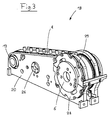
- Fig. 3 shows the middle universal slide 18 from FIG. 1 in a perspective view in isolation.
- 2 is the same carriage 18 shown in a side view, together with the rest of the cross wire provision device 10 in a partially sectioned illustration.
- the universal slide 18 shown in FIGS. 1-3 comprises one as a base or support structure of the universal slide 18 formed slide body 20.
- First on the slide body 20 is the drive roller 13 for the conveyor belt 8 with respect to the carriage body 20 rotatably mounted about a (virtual) axis of rotation 21, which to the combing wheel axis of rotation 11 is parallel and is referred to as the drive roller axis of rotation 21.
- the conveyor belt 8 is formed on its inner side with respect to the direction of rotation in the manner of a toothed belt and provided with a toothing, which with a corresponding toothing combs, which is formed on the outer peripheral surface of the driving roller 13. All in all the conveyor belt drive roller 13 thus serves as a drive pinion 13 for the type a conveyor belt 8.
- the conveyor belt drive roller 13 becomes coaxial with the drive roller axis of rotation 13 (and thus parallel to the drive wheel axis of rotation) arranged drive shaft 22 (conveyor belt drive shaft 22) driven to rotate about the drive roller axis of rotation 21.
- the conveyor belt drive shaft 22 is in two side walls 23 with respect to these in the longitudinal direction of the shaft immovable and rotatably mounted about the drive roller axis of rotation 21.
- the two side walls 23 are on one side laterally outside the through the Conveyor belts 7, 8, 9 formed cross wire feed path arranged, these side walls 23 as part of the stationary machine frame 3 of the cross wire provision device 10 are formed.
- a threaded spindle 24 provided with an external thread is provided, which extends parallel to the combing wheel axis of rotation 11 and around an axis to the combing wheel 11 parallel axis of rotation 25 (spindle axis 25) is rotatable.
- the threaded spindle 24 is in the two same side walls 23 with respect to these in the longitudinal direction of the spindle immovable and rotatably mounted about the spindle axis 25, in which also the Conveyor belt drive shaft 22 is mounted.
- the threaded spindle 24 passes through the slide body 20 and a lock nut 26, which is in a central region of the slide body 20 arranged and with this in the longitudinal direction of the spindle (i.e. in the direction parallel to Combing wheel axis of rotation 11) is coupled immovably.
- the lock nut is with one the internal thread corresponding to the external thread of the threaded spindle 24. It is designed as a divisible nut, being controlled automatically by a control signal can optionally be closed and opened again. In closed The lock nut 26 is in engagement with the thread of the threaded spindle 24.
- All universal slides 17, 18, 19 of the cross wire preparation device shown in FIGS. 1 and 2 10 are in terms of the conveyor belt drive and the drive for Purpose of moving the universal slide 17, 18, 19 transversely to the feed direction identical educated.
- the universal slides 17, 18, 19 are in relation to the combing wheel axis of rotation 11 arranged parallel to each other, the conveyor belt drive rollers 13 of the various universal slides 17, 18, 19 from a single common conveyor belt drive shaft 22 are driven. This makes synchronization simple the conveyor belts 7, 8, 9 of the various universal slides 17, 18, 19 reached.
- the lock nuts 26 of the various universal slides are also used 17, 18, 19 driven by a single common threaded spindle 24.
- the lock nuts 26 of the universal slide 17, 18, 19 become individual and independent controlled by each other to open or close them. This will give you the opportunity created, the individual universal slide 17, 18, 19 independently of one another transversely to the feed direction, although they are from a common threaded spindle 24th are driven.
- the cross wire preparation device 10 shown in FIGS. 1 and 2 is further with a Position measuring system provided, which for the automatic measurement of the position along the spindle axis 25 with respect to the stationary machine frame 3 of the cross wire preparation device 10 of each universal slide 17, 18, 19 is formed.
- the position measuring system measures the position of each universal slide 17, 18, 19 the basis of an induction resistance measurement and transmits the position data to one central machine control.
- the machine control then generates based on the measured Position data and depending on the length of the cross wires to be processed 1 and the desired position of these cross wires 1 with respect to the cross wire longitudinal direction Control signals for controlling the lock nuts 26 and the threaded spindle 24. These control signals are then sent to a drive motor (not shown).
- the universal car 17, 18, 19 shown in Fig. 1-3 are further with a combing wheel 5, 6 for combing out (separating) the cross wires 1 and / or a support wheel 27 for Support the cross wires 1 and / or a guide plate 15 for determining the position of the cross wires 1 in the cross wire longitudinal direction, the combing wheels 5, 6, Support wheels 27 and the guide plates 15 also together with the universal carriage 17, 18, 19, on which they are arranged, are displaceable transversely to the feed direction.
- the in Fig. 1 with respect to the feed direction arranged universal carriage 17, which in part is shown broken away, is on its right side with a provided the first combing wheel 5.
- FIG. 2 and 3 is on its left side with respect to FIG the feed direction with a second combing wheel 6 that with respect to a vertical mirror plane transverse to the feed direction mirror symmetrical, but otherwise essentially is identical to the first combing wheel 5.
- the one in Fig. 1 with respect to the feed direction of the universal carriage 19 arranged on the outside right is on its left Side with a support wheel 27 for supporting the cross wires 11 during their transport in the combing grooves 12 of the combing wheels 5, 6.
- the radius of the jockey wheel 27 corresponds approximately to the radial distance of the groove bottom of the combing grooves 12 from the Combing wheel axis of rotation 11.
- this universal carriage 19 On the right side is this universal carriage 19 with a vertical guide plate 15 provided on the right-hand longitudinal ends of the cross wires 1 acts to position them with respect to the cross wire longitudinal direction when the cross wires 1 on the conveyor belts 7, 8, 9 are conveyed along the guide plate 15 become.
- the automatic position measuring system is the device for automatic Moving the universal slide 17, 18, 19 transversely to the feed direction and Possibility of a plurality of different functional elements 5, 6, 15, 27 to be able to arrange the universal slide 17, 18, 19 ensures that the one shown in FIG and FIG. 2 shown cross wire provision device 10 for a multitude of different ones Cross wires 1 can be used and each quickly changes to cross wire dimensions can be customized.
- the universal slide 18 shown in FIGS. 1-3 is in the rearmost area of the slide body 20 the combing wheel 6 with respect to the slide body 20 about the combing wheel axis of rotation 11 rotatably mounted in the carriage body 20.
- the combing wheel 6 includes one first annular combing disc 28 (main combing disc 28), which with respect the carriage body 28 is rotatably mounted about the combing wheel axis of rotation 11.
- the main combing disk 28 is arranged coaxially with the axis of rotation 11 of the combing wheel Drive shaft 30 (combing wheel drive shaft 30) for rotation about its axis of rotation 11 driven.
- the comb-out wheel drive shaft 30 is in the two same side walls 23 of the stationary machine frame 3 with respect to these side walls 23 in the longitudinal direction of the shaft immovable and rotatable about the combing wheel axis of rotation 11, in which also the conveyor belt drive shaft 22 is mounted.
- the Main combing wheel 28 with the combing wheel drive shaft 30 is non-rotatable, but in Wavelength direction slidably coupled with respect to the combing wheel drive shaft 30.
- the combing wheel 6 further comprises a second annular combing disc 29 (Auxiliary combing disc 29), which is relative to the slide body 20 about the combing wheel axis of rotation 11 is rotatably mounted.
- the auxiliary combing disc 29 is parallel to the main combing disc 28 and arranged directly next to the same on the universal slide 18.
- a pinion-shaped pinion in the shape of a circular cylinder is attached to the auxiliary combing disk 29, which is arranged coaxially to the combing wheel axis of rotation 11.
- the pinion On its outer peripheral surface the pinion is provided with a toothing, which with the toothing of the conveyor belt 8 combs, which partially wraps around the pinion.
- the pinion serves as the drive pinion for the auxiliary combing disc 29 and at the same time as a deflection roller for the conveyor belt 8.
- the pinion of the auxiliary combing disk 29 is designed and arranged in such a way that that it is on the one hand by the conveyor belt 8 in the manner of a drive or transmission belt is driven to rotate about the combing wheel axis of rotation 11 and thereby the with the pinion auxiliary combing disc 29 for rotation about the combing wheel axis of rotation 11 drives.
- the pinion of the auxiliary combing disk 29 steers this Conveyor belt 8 so that its upper run on the desired path from the combing wheel 6 runs forward and down to the conveyor belt drive roller 13 runs to the To promote cross bars 1 on this track away from the combing wheel 6.
- the conveyor belt 8 has thus on the one hand the function of a conveyor belt, the cross bars 8 on it promotes upper strand.
- the annular auxiliary combing disc 29 is in its center from the combing wheel drive shaft 30 enforced.
- the auxiliary combing disk 29 is, however, in relation to the Combing wheel drive shaft 30 can be moved both in the longitudinal direction of the shaft and by the combing wheel axis of rotation 11 is rotatable. Overall, the arrangement of the auxiliary combing disc 29 with respect to the combing wheel drive shaft 30, the displaceability of the universal carriage 18 parallel to the combing wheel axis of rotation 11 is not impaired.
- each part-combing groove is designed such that its on the running direction of the combing wheel 6 (i.e. the running direction of the main and auxiliary combing disks 28, 29) front groove wall from the groove edge in the peripheral surface of the combing wheel at an angle of approximately 45 ° to a tangent to the edge of the groove in a straight line Line falls backwards to the front edge of the groove base.
- the groove bottom is in Formed essentially parallel to the circumferential line. It closes at its rear edge rear groove wall, which is essentially in the radial direction from the groove bottom to Extends peripheral surface.
- the main combing disc 28 and the auxiliary combing disc 29 driven synchronously with each other to rotate about the combing wheel axis of rotation 11, the main and auxiliary combing disks 28, 29 synchronized with one another in this way are that they are adjustable by one, but between two setting processes rotate constant phase angle offset from each other about the combing wheel axis of rotation 11.
- the phase angle or the offset between the main and auxiliary combing disks 28, 29 is set such that the groove cross sections of mutually corresponding partial combing grooves the main and auxiliary combing disks 28, 29 in to the combing wheel axis of rotation 11 in the parallel direction (i.e. in the longitudinal direction of the groove) partially or completely overlap.
- the total for the combing-out groove 12 of the combing-out wheel 6 effective groove cross-section is then smaller than the groove cross-sections in the main combing disc 28 and the auxiliary combing-out disc 29 formed part-combing grooves.
- the combing wheel 6 offers the Possibility of adapting the groove cross section or the groove thickness of the combing grooves 12 on cross wires 1 with different diameters.
- the cross wire preparation device 10 shown in FIGS. 1 and 2 is for processing of cross wires 1 are formed in a single path. That is, all cross wires can be provided in succession in the ready position in the cross wire holder 14.
- the cross wire provision device can also be used for parallel processing of Cross wires can be used in two or more lanes. Are for this purpose only to provide a sufficient number of universal slides and with appropriate Combing combing wheels, support wheels and side guide plates.
- the invention is a mesh welding system is specified, which a quick and easy adjustment of the grid welding system for Processing of cross wires with changed cross wire dimensions enabled.
Landscapes
- Engineering & Computer Science (AREA)
- Mechanical Engineering (AREA)
- Wire Processing (AREA)
Priority Applications (1)
| Application Number | Priority Date | Filing Date | Title |
|---|---|---|---|
| EP02406080A EP1428596A1 (fr) | 2002-12-09 | 2002-12-09 | Installation pour la fabrication de grilles en fils de fer |
Applications Claiming Priority (1)
| Application Number | Priority Date | Filing Date | Title |
|---|---|---|---|
| EP02406080A EP1428596A1 (fr) | 2002-12-09 | 2002-12-09 | Installation pour la fabrication de grilles en fils de fer |
Publications (1)
| Publication Number | Publication Date |
|---|---|
| EP1428596A1 true EP1428596A1 (fr) | 2004-06-16 |
Family
ID=32319728
Family Applications (1)
| Application Number | Title | Priority Date | Filing Date |
|---|---|---|---|
| EP02406080A Withdrawn EP1428596A1 (fr) | 2002-12-09 | 2002-12-09 | Installation pour la fabrication de grilles en fils de fer |
Country Status (1)
| Country | Link |
|---|---|
| EP (1) | EP1428596A1 (fr) |
Cited By (3)
| Publication number | Priority date | Publication date | Assignee | Title |
|---|---|---|---|---|
| FR2895288A1 (fr) * | 2005-12-22 | 2007-06-29 | Fabrication Rationalisee D Arm | Installation de fabrication d'armatures pour beton arme. |
| WO2009124520A1 (fr) * | 2008-04-07 | 2009-10-15 | Bam Ag | Machine pour la production de treillis soudé pour béton armé mono-axe |
| CN113677453A (zh) * | 2019-04-04 | 2021-11-19 | Mbk机械工程有限公司 | 用于装配笼式焊接机的装置及笼式焊接机 |
Citations (4)
| Publication number | Priority date | Publication date | Assignee | Title |
|---|---|---|---|---|
| FR2246477A1 (en) * | 1973-10-03 | 1975-05-02 | Herlin Bernard | Device to feed individual long bars for machining - uses oscillating arm with magnet or suction to lift rods |
| US4748309A (en) * | 1986-04-02 | 1988-05-31 | Evg Entwicklungs-U. Verwertungs-Gesellschaft M.B.H. | Multi-spot resistance-welding machine |
| EP0319950A1 (fr) * | 1987-12-07 | 1989-06-14 | Emil Jäger GmbH & Co. KG | Dispositif pour l'amenage de fils transversaux dans une soudeuse de treillis |
| DE10016036A1 (de) * | 2000-03-31 | 2001-10-18 | Tracto Technik | Metallbearbeitungsmaschine mit Zuführvorrichtung für stabförmige Werkstücke |
-
2002
- 2002-12-09 EP EP02406080A patent/EP1428596A1/fr not_active Withdrawn
Patent Citations (4)
| Publication number | Priority date | Publication date | Assignee | Title |
|---|---|---|---|---|
| FR2246477A1 (en) * | 1973-10-03 | 1975-05-02 | Herlin Bernard | Device to feed individual long bars for machining - uses oscillating arm with magnet or suction to lift rods |
| US4748309A (en) * | 1986-04-02 | 1988-05-31 | Evg Entwicklungs-U. Verwertungs-Gesellschaft M.B.H. | Multi-spot resistance-welding machine |
| EP0319950A1 (fr) * | 1987-12-07 | 1989-06-14 | Emil Jäger GmbH & Co. KG | Dispositif pour l'amenage de fils transversaux dans une soudeuse de treillis |
| DE10016036A1 (de) * | 2000-03-31 | 2001-10-18 | Tracto Technik | Metallbearbeitungsmaschine mit Zuführvorrichtung für stabförmige Werkstücke |
Cited By (3)
| Publication number | Priority date | Publication date | Assignee | Title |
|---|---|---|---|---|
| FR2895288A1 (fr) * | 2005-12-22 | 2007-06-29 | Fabrication Rationalisee D Arm | Installation de fabrication d'armatures pour beton arme. |
| WO2009124520A1 (fr) * | 2008-04-07 | 2009-10-15 | Bam Ag | Machine pour la production de treillis soudé pour béton armé mono-axe |
| CN113677453A (zh) * | 2019-04-04 | 2021-11-19 | Mbk机械工程有限公司 | 用于装配笼式焊接机的装置及笼式焊接机 |
Similar Documents
| Publication | Publication Date | Title |
|---|---|---|
| DE19522189C2 (de) | Gruppier- und Puffervorrichtung | |
| DE2803223C2 (fr) | ||
| DE2903461C2 (fr) | ||
| EP1525811A1 (fr) | Dispositif et procédé pour transférer articles en forme de tige | |
| EP3277605B1 (fr) | Convoyeur à bande à auges pour transporter des poissons de manière transversale par rapport à leur extension longitudinale dans une direction de transport, ensemble et procédé | |
| DE3641064A1 (de) | Foerdervorrichtung zum foerdern von einem doppelstrang abgetrennter stabfoermiger artikel der tabakverarbeitenden industrie | |
| DE102013206138A1 (de) | Vorrichtung zum Komplettieren eines Formatsatzes von Produkten | |
| DE69718374T2 (de) | Verfahren und Vorrichtung zum geordneten Abführen von ungeordnet zugeführten Produkten | |
| DE1166674B (de) | Zwischenfoerderer fuer nebeneinanderliegende Reihen von Filtern oder anderen stabfoermigen Gegenstaenden | |
| DE4343477C1 (de) | Verfahren sowie Vorrichtung zum Verteilen von Behältern oder dergleichen Fördergut auf einen mehrreihigen Förderabschnitt | |
| DE3729081A1 (de) | Aufgabefoerderer zum aufgeben von stueckgutteilen auf einen aufnahmefoerderer | |
| EP3802382B1 (fr) | Dispositif de transport et procédé de transport d'applicateurs de tampon | |
| DE10351068B4 (de) | Staffeltrommel | |
| DE1285931B (de) | Zwischenfoerderer fuer nebeneinanderliegende Reihen von Filterstaeben, Zigaretten oder anderen stabfoermigen Gegenstaenden | |
| DE2035157C3 (de) | Vorrichtung zum kontinuierlichen Versetzen von zunächst n koaxial nebeneinander in quer zur Längsrichtung nacheinander liegenden stabförmigen Artikeln der Tabak verarbeitenden Industrie | |
| DE3224330C2 (fr) | ||
| EP1428596A1 (fr) | Installation pour la fabrication de grilles en fils de fer | |
| EP2384652A2 (fr) | Dispositif de remplissage de combles avec des articles en forme de tiges et machine de fabrication pour articles en forme de tiges dotée d'un tel dispositif | |
| EP0297201B1 (fr) | Dispositif d'amenée d'éléments longitudinaux coupés à une certaine longueur à une soudeuse de treillis | |
| EP1428594A2 (fr) | Dispositif de séparation de fils | |
| EP1428592A1 (fr) | Dispositif de séparation de fils | |
| DE29521082U1 (de) | Gruppier- und Puffervorrichtung | |
| DE2822823A1 (de) | Vorrichtung zum foerdern von behaeltern | |
| DE4406089A1 (de) | Verfahren und Vorrichtung zum Abfüllen von Tabletten oder dergleichen in Tablettenröhrchen | |
| EP3613293B1 (fr) | Dispositif et procédé de traitement de saucisses |
Legal Events
| Date | Code | Title | Description |
|---|---|---|---|
| PUAI | Public reference made under article 153(3) epc to a published international application that has entered the european phase |
Free format text: ORIGINAL CODE: 0009012 |
|
| AK | Designated contracting states |
Kind code of ref document: A1 Designated state(s): AT BE BG CH CY CZ DE DK EE ES FI FR GB GR IE IT LI LU MC NL PT SE SI SK TR |
|
| AX | Request for extension of the european patent |
Extension state: AL LT LV MK RO SI |
|
| 17P | Request for examination filed |
Effective date: 20040830 |
|
| AKX | Designation fees paid |
Designated state(s): AT BE BG CH CY CZ DE DK EE ES FI FR GB GR IE IT LI LU MC NL PT SE SI SK TR |
|
| 17Q | First examination report despatched |
Effective date: 20050401 |
|
| GRAP | Despatch of communication of intention to grant a patent |
Free format text: ORIGINAL CODE: EPIDOSNIGR1 |
|
| STAA | Information on the status of an ep patent application or granted ep patent |
Free format text: STATUS: THE APPLICATION IS DEEMED TO BE WITHDRAWN |
|
| 18D | Application deemed to be withdrawn |
Effective date: 20051122 |