EP1428630A1 - Klammererfassungsmechanismus für elektrische heftvorrichtung - Google Patents
Klammererfassungsmechanismus für elektrische heftvorrichtung Download PDFInfo
- Publication number
- EP1428630A1 EP1428630A1 EP02760713A EP02760713A EP1428630A1 EP 1428630 A1 EP1428630 A1 EP 1428630A1 EP 02760713 A EP02760713 A EP 02760713A EP 02760713 A EP02760713 A EP 02760713A EP 1428630 A1 EP1428630 A1 EP 1428630A1
- Authority
- EP
- European Patent Office
- Prior art keywords
- actuator
- staples
- staple cartridge
- passage
- staple
- Prior art date
- Legal status (The legal status is an assumption and is not a legal conclusion. Google has not performed a legal analysis and makes no representation as to the accuracy of the status listed.)
- Withdrawn
Links
Images



Classifications
-
- B—PERFORMING OPERATIONS; TRANSPORTING
- B25—HAND TOOLS; PORTABLE POWER-DRIVEN TOOLS; MANIPULATORS
- B25C—HAND-HELD NAILING OR STAPLING TOOLS; MANUALLY OPERATED PORTABLE STAPLING TOOLS
- B25C5/00—Manually operated portable stapling tools; Hand-held power-operated stapling tools; Staple feeding devices therefor
- B25C5/16—Staple-feeding devices, e.g. with feeding means, supports for staples or accessories concerning feeding devices
- B25C5/1689—Staple-feeding devices, e.g. with feeding means, supports for staples or accessories concerning feeding devices with means for indicating the number of staples remaining
-
- B—PERFORMING OPERATIONS; TRANSPORTING
- B25—HAND TOOLS; PORTABLE POWER-DRIVEN TOOLS; MANIPULATORS
- B25C—HAND-HELD NAILING OR STAPLING TOOLS; MANUALLY OPERATED PORTABLE STAPLING TOOLS
- B25C5/00—Manually operated portable stapling tools; Hand-held power-operated stapling tools; Staple feeding devices therefor
- B25C5/16—Staple-feeding devices, e.g. with feeding means, supports for staples or accessories concerning feeding devices
-
- B—PERFORMING OPERATIONS; TRANSPORTING
- B27—WORKING OR PRESERVING WOOD OR SIMILAR MATERIAL; NAILING OR STAPLING MACHINES IN GENERAL
- B27F—DOVETAILED WORK; TENONS; SLOTTING MACHINES FOR WOOD OR SIMILAR MATERIAL; NAILING OR STAPLING MACHINES
- B27F7/00—Nailing or stapling; Nailed or stapled work
- B27F7/17—Stapling machines
- B27F7/38—Staple feeding devices
Definitions
- the present invention relates to amechanismof detecting the presence of staples, which are accommodated in a staple cartridge, in an electric stapler.
- This staple cartridge is mounted in a passage, which is formed in a magazine portion of the stapler body, used for attaching the cartridge.
- a staple at the lead of the sheet staples is stricken out while both sides of the staple are being bent, and the following staples are successively stricken out while both sides of the staples are being bent.
- this type electric stapler when a quantity of residual sheet staples in the staple cartridge are decreased, it is necessary to pick up the cartridge from the magazine portion and replace it with a new cartridge. Therefore, it is necessary to provide a staple detecting sensor for detecting the quantity of residual sheet staples in the staple cartridge.
- a space of the passage provided in the stapler body, to which the staple cartridge is attached is small. Therefore, even when a common microswitch is attached into the space, a stroke of the switch is too short. Accordingly, the microswitch is operated even when the staple cartridge is moved a little. For example, even when a sufficiently large quantity of staples are left in the cartridge, when the sheet staples are deformed being badly warped, the actuator of the microswitch comes into action. Therefore, the reliability of detection is unavoidably deteriorated. In the case where the microswitch is arranged in the passage, when the actuator is arranged making a right angle with the passage, it obstructs the attaching and detaching work of the staple cartridge.
- the present invention has been accomplished to solve the above problems. It is an object of the present invention to provide a mechanism of detecting staples in an electric stapler by which a quantity of residual staples can be positively detected even when a space, in which the mechanism is arranged, is small, when a profile and mode of operation of the actuator are improved.
- the present invention provides a mechanism of detecting staples in an electric stapler.
- the electric stapler is composed as follows. A passage for attaching a staple cartridge is formed in a magazine portion of the stapler body. In the staple cartridge, sheet staples, in which a large number of linear staples are connected to each other being formed into a sheet-shape, are accommodated. Both sides of the lead staple and the following staples of the sheet staples are successively bent and stricken out by the electric stapler.
- the mechanism of detecting staples is composed as follows.
- a staple detection sensor both side portions of the end of the actuator of which are tapered, is arranged so that both the side portions can be directed to an entrance of the passage and the end of the actuator can be engaged with an upper or a lower face of the sheet staples of the staple cartridge attached into the passage.
- the actuator is attached so that the actuator can be swung and tilted in the perpendicular direction to the longitudinal direction of the passage, and the actuator is biased by a spring so that it can be raised obliquely at all times.
- reference numeral 1 is a stapler body
- reference numeral 3 is a staple cartridge
- reference numeral 4 is a passage
- reference numeral 8 is an actuator.
- Fig. 1 is a perspective view of the stapler body of the electric stapler
- Fig. 2 is a simplified view of the side of the stapler body of the electric stapler
- Fig. 3 is a rear view of the stapler body of the electric stapler.
- the staple cartridge 3 shown in Figs. 4 and 5 is detachably attached to the magazine portion 2 of the stapler body 1.
- a plurality of stages of sheet staples "a" shown in Fig. 6
- a large number of linear staples are connected with each other being formed into a sheet-shape as shown in Fig. 6, are stacked and accommodated.
- the passage 4 for attaching the cartridge is formed in the magazine portion 2 of the stapler body 1.
- the above staple cartridge 3 is inserted and attached into the above passage 4.
- the driver plate 5 provided in the stapler body 1 is driven upward, and a staple at the lead of the sheet staples "a” is made to penetrate sheets of paper to be stapled.
- the upper arm 12 is driven downward so that both sides of the staple, which has penetrated the sheets of paper to be stapled, are bent.
- the driver plate 5 and the arm 12 are respectively descended and ascended to the initial position, and the sheet staples are fed forward by a feeding means (not shown) so as to prepare for the next binding operation.
- the aforementioned operation is repeated, and both sides of the staples are successively bent and stricken out.
- the mechanism of bending both sides of the lead staple and striking the staple is well known. Therefore, the explanations are omitted here.
- the sensor 7 for detecting the staple is arranged in the neighborhood on the cartridge introducing portion side of the passage 4 of the above magazine portion 2.
- the switch is turned on and off when the. actuator 8 provided in the switch body 7a is operated. Both sides 8a, 8b of the end portion of the actuator 8 are tapered. In this way, the actuator 8 is formed into a triangular-plate-shape or trapezoidal-plate-shape.
- the actuator 8 is attached so that it can be tilted with respect to the switch body 7a. The tilting direction is perpendicular to the face of the actuator 8. When the actuator 8 rises, it is a little inclined with respect to the perpendicular direction.
- the actuator 8 is biased by a spring not shown so that it can rise at all times.
- the detection sensor 7 is arranged in the neighborhood of the cartridge 3 introducing portion side (the entrance side) of the passage 4. At this time, the staple detection sensor 7 is attached so that both sides 8a, 8b described above can be directed to the entrance of the passage 4. At this time, the actuator 8 protrudes into the passage 4.
- the guide passage 10 of the sheet staples "a” and the knob 11 are provided in the staple cartridge 3.
- the opening 9 is formed at the rear portion corresponding to the detection sensor 7 when the staple cartridge 3 is inserted into the magazine portion 2 of the stapler body 1, that is, at the position on the knob side.
- the lower face of the sheet staples "a", which are provided inside, is exposed from this opening 9.
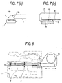
- Fig. 8 is a side view showing a state in which the staple cartridge 3 is attached, and Fig.
- FIG. 9 is a rear view showing a state in which the staple cartridge 3 is attached.
- the actuator 8 proceeds into the cartridge 3 from the opening 9, which is formed in the lower portion of the staple cartridge 3, by a force of the spring.
- the actuator 8 is engaged with the lower face of the sheet staples "a", which are accommodated in the cartridge 3, and tilted as shown in Fig. 7(b). This tilting state of the actuator 8 is maintained.
- the staple cartridge 3 may be pulled out in the opposite direction to the inserting direction and replaced with a new staple cartridge 3.
- the edge 9a (shown in Fig. 5) of the opening 9 of the staple cartridge 3 comes into contact with and pushes the inclined side portion 8b of the front side of the actuator 8. Since the actuator 8 obliquely rises, when the inclined side portion 8b is pushed, the actuator 8 is swung and tilted resisting the spring force. Therefore, the actuator 8 does not obstruct the insertion of the staple cartridge 3. Accordingly, the staple cartridge 3 can be smoothly and positively attached to and detached from the stapler.
- a.plurality of stages of sheet staples are stacked in the staple cartridge 3 and the thus stacked sheet staples are successively consumed from the upper stage.
- the stacked sheet staples are successively consumed from the. lower stage.
- long sheet staples are spirally accommodated in the staple cartridge.
- the staple detection sensor may be arranged on the upper side of the passage, and the actuator may be composed so that it can protrude from top to bottom.
- the actuator 8 of the above detection sensor is not protruded to and retracted from the passage 4 under the condition that it rises perpendicularly, but the detection sensor is tilted with respect to the passage 4. Therefore, the operation stroke of the actuator 8 is extended. Accordingly, even when a space of the passage 4 is small, no malfunction of the actuator 8 is caused, and the presence of staples can be positively detected. Therefore, the reliability of detection is high.
- the actuator is composed in such a manner that both side portions 8a, 8b of the end portion of the actuator are tapered and the actuator can be freely tilted, and when the actuator collides with the staple cartridge 3, it can move so as to escape from the staple cartridge 3. Therefore, the actuator 3 does not obstruct the attaching work of the staple cartridge 3. Accordingly, a big relief margin of the actuator 8 is not required.
Landscapes
- Engineering & Computer Science (AREA)
- Mechanical Engineering (AREA)
- Life Sciences & Earth Sciences (AREA)
- Forests & Forestry (AREA)
- Portable Nailing Machines And Staplers (AREA)
- Dovetailed Work, And Nailing Machines And Stapling Machines For Wood (AREA)
Applications Claiming Priority (3)
| Application Number | Priority Date | Filing Date | Title |
|---|---|---|---|
| JP2001253528A JP4784020B2 (ja) | 2001-08-23 | 2001-08-23 | 電動ホッチキスにおけるステープルの検出機構 |
| JP2001253528 | 2001-08-23 | ||
| PCT/JP2002/008482 WO2003018268A1 (en) | 2001-08-23 | 2002-08-22 | Staple detection mechanism of electric stapler |
Publications (2)
| Publication Number | Publication Date |
|---|---|
| EP1428630A1 true EP1428630A1 (de) | 2004-06-16 |
| EP1428630A4 EP1428630A4 (de) | 2008-06-11 |
Family
ID=19081841
Family Applications (1)
| Application Number | Title | Priority Date | Filing Date |
|---|---|---|---|
| EP02760713A Withdrawn EP1428630A4 (de) | 2001-08-23 | 2002-08-22 | Klammererfassungsmechanismus für elektrische heftvorrichtung |
Country Status (7)
| Country | Link |
|---|---|
| US (1) | US6892919B2 (de) |
| EP (1) | EP1428630A4 (de) |
| JP (1) | JP4784020B2 (de) |
| KR (1) | KR100777472B1 (de) |
| CN (1) | CN1277659C (de) |
| TW (1) | TW555629B (de) |
| WO (1) | WO2003018268A1 (de) |
Cited By (1)
| Publication number | Priority date | Publication date | Assignee | Title |
|---|---|---|---|---|
| EP1867441A4 (de) * | 2005-04-07 | 2009-06-24 | Max Co Ltd | Elektrische heftmaschine |
Families Citing this family (11)
| Publication number | Priority date | Publication date | Assignee | Title |
|---|---|---|---|---|
| WO2003018267A1 (en) * | 2001-08-23 | 2003-03-06 | Max Co., Ltd. | Staple cartridge of electric stapler |
| JP4120225B2 (ja) * | 2002-01-18 | 2008-07-16 | マックス株式会社 | カートリッジ |
| JP4239732B2 (ja) * | 2003-07-07 | 2009-03-18 | マックス株式会社 | 電動ステープラーの駆動機構 |
| JP4561210B2 (ja) | 2004-07-16 | 2010-10-13 | マックス株式会社 | ステープルカートリッジ |
| GB2428018B (en) * | 2005-07-06 | 2010-07-28 | Acco Uk Ltd | Stapling device |
| US7784661B2 (en) * | 2005-10-04 | 2010-08-31 | Max Co., Ltd. | Electric stapler |
| DE102006046842A1 (de) * | 2006-10-02 | 2008-04-03 | Robert Bosch Gmbh | Eintreibgerät zum Eintreiben von Befestigungsmitteln |
| KR200449206Y1 (ko) | 2008-06-17 | 2010-06-24 | 한일이화주식회사 | 타카핀 감지센서가 구비된 타카장치 |
| JP6870280B2 (ja) * | 2015-12-22 | 2021-05-12 | マックス株式会社 | ステープラ、後処理装置及び画像形成システム |
| EP3378598A1 (de) * | 2017-03-20 | 2018-09-26 | HILTI Aktiengesellschaft | Verfahren zum betreiben einer eintreibvorrichtung |
| CN110487466B (zh) * | 2019-09-19 | 2020-11-13 | 上海晨光文具股份有限公司 | 一种订书机打钉力检测装置及其检测方法 |
Family Cites Families (15)
| Publication number | Priority date | Publication date | Assignee | Title |
|---|---|---|---|---|
| JPS41266B1 (de) * | 1963-02-14 | 1966-01-12 | ||
| US4623082A (en) * | 1985-05-14 | 1986-11-18 | Max Co. Ltd. | Electronic stapler |
| JPS6279977A (ja) * | 1985-09-24 | 1987-04-13 | キヤノン株式会社 | ステ−プラ−の針送り装置 |
| US5230457A (en) * | 1987-11-16 | 1993-07-27 | Canon Kabushiki Kaisha | Sheet stapler |
| JPH0730282Y2 (ja) * | 1990-09-14 | 1995-07-12 | マックス株式会社 | 電動ホッチキスにおけるステープル検出装置 |
| EP0475436B1 (de) * | 1990-09-14 | 1996-01-31 | Max Co., Ltd. | Elektrische Klammermaschine mit unbeweglichem ortsfestem Magazin |
| US5269503A (en) * | 1990-09-29 | 1993-12-14 | Canon Kabushiki Kaisha | Sheet processing apparatus with detachable staple cartridge and cartridge locking means |
| SE500252C2 (sv) * | 1993-06-02 | 1994-05-24 | Isaberg Ab | Häftapparat för indrivning av häftklamrar |
| US5529235A (en) * | 1994-04-28 | 1996-06-25 | Ethicon Endo-Surgery, Inc. | Identification device for surgical instrument |
| JP2932438B2 (ja) * | 1995-02-28 | 1999-08-09 | マックス株式会社 | 電動ホッチキスにおける自動綴り準備機構 |
| US6050471A (en) * | 1996-10-23 | 2000-04-18 | Max Co., Ltd. | Electric stapler |
| JP3436029B2 (ja) * | 1996-12-20 | 2003-08-11 | マックス株式会社 | 電動ステープラのステープル検出装置 |
| JP2000167782A (ja) * | 1998-12-02 | 2000-06-20 | Nisca Corp | ステープラ用針パッケージ及びステープラ装置 |
| US6474633B1 (en) * | 1999-10-04 | 2002-11-05 | Canon Kabushiki Kaisha | Stapler with interchangeable cartridges |
| JP4419335B2 (ja) * | 2001-03-12 | 2010-02-24 | マックス株式会社 | ステープルカートリッジシステム |
-
2001
- 2001-08-23 JP JP2001253528A patent/JP4784020B2/ja not_active Expired - Fee Related
-
2002
- 2002-08-22 US US10/487,260 patent/US6892919B2/en not_active Expired - Fee Related
- 2002-08-22 KR KR1020047002592A patent/KR100777472B1/ko not_active Expired - Fee Related
- 2002-08-22 EP EP02760713A patent/EP1428630A4/de not_active Withdrawn
- 2002-08-22 CN CNB028161637A patent/CN1277659C/zh not_active Expired - Fee Related
- 2002-08-22 WO PCT/JP2002/008482 patent/WO2003018268A1/ja not_active Ceased
- 2002-08-23 TW TW091119111A patent/TW555629B/zh active
Cited By (2)
| Publication number | Priority date | Publication date | Assignee | Title |
|---|---|---|---|---|
| EP1867441A4 (de) * | 2005-04-07 | 2009-06-24 | Max Co Ltd | Elektrische heftmaschine |
| US7946462B2 (en) | 2005-04-07 | 2011-05-24 | Max Co., Ltd. | Electric stapler |
Also Published As
| Publication number | Publication date |
|---|---|
| CN1277659C (zh) | 2006-10-04 |
| KR20040027979A (ko) | 2004-04-01 |
| CN1543390A (zh) | 2004-11-03 |
| WO2003018268A1 (en) | 2003-03-06 |
| JP4784020B2 (ja) | 2011-09-28 |
| US20040195288A1 (en) | 2004-10-07 |
| EP1428630A4 (de) | 2008-06-11 |
| US6892919B2 (en) | 2005-05-17 |
| KR100777472B1 (ko) | 2007-11-19 |
| TW555629B (en) | 2003-10-01 |
| JP2003062765A (ja) | 2003-03-05 |
Similar Documents
| Publication | Publication Date | Title |
|---|---|---|
| US6892919B2 (en) | Staple detection mechanism of electric stapler | |
| US4463890A (en) | Staplers | |
| US7118019B2 (en) | Jam resistant staple holding track for staplers | |
| EP1174224B1 (de) | Kraftverstärkender Mechanismus für Hefter | |
| US7124924B2 (en) | Desktop stapler striker/anvil alignment system | |
| US20060213950A1 (en) | Spring energized desktop stapler | |
| US20100270353A1 (en) | Stapler | |
| US7143921B2 (en) | Staple cartridge for electric stapler | |
| CN1988986B (zh) | 订书机以及订书钉装订盒 | |
| JP2025083509A (ja) | ステープラ | |
| CN100548587C (zh) | 订书钉装订匣 | |
| CN100441383C (zh) | 订书钉脚引导机构 | |
| SE517108C2 (sv) | Häftapparat | |
| US7234622B2 (en) | Stapler, cartridge for stapler, and system having the stapler and cartridge in combination | |
| JP2003291077A (ja) | ステープラ | |
| US7757921B2 (en) | Driving machine | |
| US20070251970A1 (en) | Spring-loaded desktop stapler with interchangeable staple cartridges | |
| JP4254500B2 (ja) | ステープラーのワンタッチオープン機構 | |
| JP2009208188A (ja) | ステープラ | |
| JP2004209561A (ja) | ステープル脚ガイド機構 | |
| JPH11254347A (ja) | ロールステープルカートリッジにおけるステープル切断機構 | |
| CN101189102A (zh) | 订书机 | |
| JP2004009213A (ja) | 電動ホッチキスにおけるセルフプライミング検知機構 | |
| JP2003291078A (ja) | ステープラ |
Legal Events
| Date | Code | Title | Description |
|---|---|---|---|
| PUAI | Public reference made under article 153(3) epc to a published international application that has entered the european phase |
Free format text: ORIGINAL CODE: 0009012 |
|
| 17P | Request for examination filed |
Effective date: 20040301 |
|
| AK | Designated contracting states |
Kind code of ref document: A1 Designated state(s): AT BE BG CH CY CZ DE DK EE ES FI FR GB GR IE IT LI LU MC NL PT SE SK TR |
|
| AX | Request for extension of the european patent |
Extension state: AL LT LV MK RO SI |
|
| A4 | Supplementary search report drawn up and despatched |
Effective date: 20080515 |
|
| GRAP | Despatch of communication of intention to grant a patent |
Free format text: ORIGINAL CODE: EPIDOSNIGR1 |
|
| STAA | Information on the status of an ep patent application or granted ep patent |
Free format text: STATUS: THE APPLICATION IS DEEMED TO BE WITHDRAWN |
|
| 18D | Application deemed to be withdrawn |
Effective date: 20091207 |