EP1428780B1 - Vorrichtung zum Zuführen von Folie zur Herstellung von Folienbeuteln und Vorrichtung zur Herstellung von Folienbeuteln - Google Patents
Vorrichtung zum Zuführen von Folie zur Herstellung von Folienbeuteln und Vorrichtung zur Herstellung von Folienbeuteln Download PDFInfo
- Publication number
- EP1428780B1 EP1428780B1 EP02026889A EP02026889A EP1428780B1 EP 1428780 B1 EP1428780 B1 EP 1428780B1 EP 02026889 A EP02026889 A EP 02026889A EP 02026889 A EP02026889 A EP 02026889A EP 1428780 B1 EP1428780 B1 EP 1428780B1
- Authority
- EP
- European Patent Office
- Prior art keywords
- film
- roller
- dancer
- looping
- rollers
- Prior art date
- Legal status (The legal status is an assumption and is not a legal conclusion. Google has not performed a legal analysis and makes no representation as to the accuracy of the status listed.)
- Expired - Lifetime
Links
Images



Classifications
-
- B—PERFORMING OPERATIONS; TRANSPORTING
- B65—CONVEYING; PACKING; STORING; HANDLING THIN OR FILAMENTARY MATERIAL
- B65H—HANDLING THIN OR FILAMENTARY MATERIAL, e.g. SHEETS, WEBS, CABLES
- B65H23/00—Registering, tensioning, smoothing or guiding webs
- B65H23/04—Registering, tensioning, smoothing or guiding webs longitudinally
- B65H23/18—Registering, tensioning, smoothing or guiding webs longitudinally by controlling or regulating the web-advancing mechanism, e.g. mechanism acting on the running web
- B65H23/182—Registering, tensioning, smoothing or guiding webs longitudinally by controlling or regulating the web-advancing mechanism, e.g. mechanism acting on the running web in unwinding mechanisms or in connection with unwinding operations
-
- B—PERFORMING OPERATIONS; TRANSPORTING
- B65—CONVEYING; PACKING; STORING; HANDLING THIN OR FILAMENTARY MATERIAL
- B65H—HANDLING THIN OR FILAMENTARY MATERIAL, e.g. SHEETS, WEBS, CABLES
- B65H19/00—Changing the web roll
- B65H19/10—Changing the web roll in unwinding mechanisms or in connection with unwinding operations
- B65H19/18—Attaching, e.g. pasting, the replacement web to the expiring web
-
- B—PERFORMING OPERATIONS; TRANSPORTING
- B65—CONVEYING; PACKING; STORING; HANDLING THIN OR FILAMENTARY MATERIAL
- B65H—HANDLING THIN OR FILAMENTARY MATERIAL, e.g. SHEETS, WEBS, CABLES
- B65H23/00—Registering, tensioning, smoothing or guiding webs
- B65H23/04—Registering, tensioning, smoothing or guiding webs longitudinally
- B65H23/042—Sensing the length of a web loop
-
- B—PERFORMING OPERATIONS; TRANSPORTING
- B65—CONVEYING; PACKING; STORING; HANDLING THIN OR FILAMENTARY MATERIAL
- B65H—HANDLING THIN OR FILAMENTARY MATERIAL, e.g. SHEETS, WEBS, CABLES
- B65H23/00—Registering, tensioning, smoothing or guiding webs
- B65H23/04—Registering, tensioning, smoothing or guiding webs longitudinally
- B65H23/18—Registering, tensioning, smoothing or guiding webs longitudinally by controlling or regulating the web-advancing mechanism, e.g. mechanism acting on the running web
- B65H23/182—Registering, tensioning, smoothing or guiding webs longitudinally by controlling or regulating the web-advancing mechanism, e.g. mechanism acting on the running web in unwinding mechanisms or in connection with unwinding operations
- B65H23/185—Registering, tensioning, smoothing or guiding webs longitudinally by controlling or regulating the web-advancing mechanism, e.g. mechanism acting on the running web in unwinding mechanisms or in connection with unwinding operations motor-controlled
-
- B—PERFORMING OPERATIONS; TRANSPORTING
- B65—CONVEYING; PACKING; STORING; HANDLING THIN OR FILAMENTARY MATERIAL
- B65H—HANDLING THIN OR FILAMENTARY MATERIAL, e.g. SHEETS, WEBS, CABLES
- B65H2511/00—Dimensions; Position; Numbers; Identification; Occurrences
- B65H2511/10—Size; Dimensions
- B65H2511/11—Length
- B65H2511/112—Length of a loop, e.g. a free loop or a loop of dancer rollers
-
- B—PERFORMING OPERATIONS; TRANSPORTING
- B65—CONVEYING; PACKING; STORING; HANDLING THIN OR FILAMENTARY MATERIAL
- B65H—HANDLING THIN OR FILAMENTARY MATERIAL, e.g. SHEETS, WEBS, CABLES
- B65H2513/00—Dynamic entities; Timing aspects
- B65H2513/10—Speed
-
- B—PERFORMING OPERATIONS; TRANSPORTING
- B65—CONVEYING; PACKING; STORING; HANDLING THIN OR FILAMENTARY MATERIAL
- B65H—HANDLING THIN OR FILAMENTARY MATERIAL, e.g. SHEETS, WEBS, CABLES
- B65H2601/00—Problem to be solved or advantage achieved
- B65H2601/20—Avoiding or preventing undesirable effects
- B65H2601/22—Gravity effects, e.g. effect of weight of handled material
-
- Y—GENERAL TAGGING OF NEW TECHNOLOGICAL DEVELOPMENTS; GENERAL TAGGING OF CROSS-SECTIONAL TECHNOLOGIES SPANNING OVER SEVERAL SECTIONS OF THE IPC; TECHNICAL SUBJECTS COVERED BY FORMER USPC CROSS-REFERENCE ART COLLECTIONS [XRACs] AND DIGESTS
- Y10—TECHNICAL SUBJECTS COVERED BY FORMER USPC
- Y10T—TECHNICAL SUBJECTS COVERED BY FORMER US CLASSIFICATION
- Y10T156/00—Adhesive bonding and miscellaneous chemical manufacture
- Y10T156/17—Surface bonding means and/or assemblymeans with work feeding or handling means
Definitions
- the invention relates to a device for feeding films for the production of Foil bags and a device for producing foil bags.
- Such machines according to the preamble of claim 1 and claim 10 are from DE 198 247 98 (US 6340130) known.
- a film web is unwound from a supply roll by a stationary deflection roller and a movably mounted dancer roller and deflected by a trigger device further promoted. From this it is also known to have two dancer rollers that are fixed together are coupled to use. The dancer roller is used to unroll the film web to control the supply roll.
- the object of the present invention is therefore a device for feeding film to provide for the production of foil bags with which the unrolling of the foil can be controlled from the supply roll without the film a strong or exposed to uncontrolled tensile stress. It is also a task of Invention to provide a device for the production of foil bags, the comprises an improved device for feeding film.
- This coupling enables the dancer rollers to move so that they roll off the film can be controlled from the supply roll. At the same time they hang Dancer rolls with their weight on the opposite ends of a flexible Suspension, so that their weight is at least partially or completely compensated and their weight no or only a small tensile stress in the film and therefore none Stretching caused. Furthermore, by coupling the dancer rollers the flexible suspension enables a jerky movement of the dancer rollers because they can set each other in motion.
- a device according to the invention for producing film bags comprises at least two devices for feeding film according to the invention and one Welding device for welding the two foils.
- Welding device for welding the two foils.
- a slide is a pattern from a front of a to be manufactured foil bag and the other foil contain a pattern of the back can, is a precise merging of the two foils in a predetermined, relative Position of the two patterns to each other is essential. Since with the invention Device for feeding film a strong or uncontrolled stretching of the films is prevented, it is easy to bring the foils together precisely. The Production of foil bags is thus simplified. You can also use one or more additional foils are fed and sealed, e.g. a bottom film that is perforated and can be folded and inserted between the two foils.
- Fig. 1 is a device for feeding film for the production of film bags shown.
- a film supply roll 5 is in a supply roll holder 3 which can be driven by a drive held.
- a film 2 is shown unrolled from the film supply roll 5.
- a film sensor device 6 is arranged downstream of the supply roll 5.
- the Film sensor device 6 comprises a plurality of deflection rollers 7, 15, 16, 22 and two Dancer rollers 8, 9.
- the deflection and dancer rollers 7, 8, 9, 15, 16, 22 are arranged that the film 2 in the order of the first deflection roller 7, the first dancer roller 8, the second deflection roller 15, the third deflection roller 16, the second dancer roller 9 and the fourth deflecting roller 22 alternately downwards and upwards is redirected.
- a conveyor device 4 is located downstream of the film sensor device 6 consisting of two rollers, at least one of which is driven, arranged the two rollers of the conveying device 4 cooperate in such a way that the film 2 absorb and promote between themselves.
- a conveyor can also be arranged further downstream than the rollers 4, so that the rollers 4 serve only as deflection rollers that are not driven.
- the deflection rollers 7 and 15 are each arranged at approximately the same height. The same applies for the deflection rollers 16 and 22.
- the dancer roller 8 can vary between the height of the Move deflection roller 7 and 16. Accordingly, the dancer roller 9 between the Move the height of the guide rollers 15 and 16.
- the dancer rolls 8.9 can run along move vertical guides, the vertical guides in Fig. 1 not are shown.
- the dancer roller 8 is arranged in a hanging film loop which is open at the top.
- the dancer roller 9 is provided in a film loop which is open at the bottom.
- the Foil loop of the dancer roller 9 is held upwards by the dancer roller 9.
- the bearing 10 of the first dancer roller 8 and the bearing 11 of the second dancer roller 9 are with each other via a belt 12 which is deflected via deflection wheels 13, 14 coupled.
- the weight of the bearings 10 and 11 and the first and second dancer roll 8, 9 each hangs on the suspension 12. As a result, the dancer rollers 8, 9 load with their Do not weight the film 2.
- the weight of the dancer rollers 8, 9 is neutralized, e.g. the dancer roller 8 through a weight, a spring, an elastic band or similar can be easily preloaded without stretch the film 2 noticeably or permanently. This can create a slight tension in the Film 2 are generated, which keeps the film 2 stretched between the individual rollers.
- neutralizing the dancer roll weights and the controlled provision of one the film tension can be adjusted as desired, so that too thin and sensitive foils can be processed.
- the deflection wheels 13, 14 of the suspension are arranged approximately at the same height.
- the Suspension 12 is arranged horizontally between the two deflection wheels 13 and 14. In addition to the deflection wheels 13 and 14, the suspension 12 runs vertically along the Dancer roll guide.
- FIGS. 2a, 2b The mode of operation of the film sensor device is explained with reference to FIGS. 2a, 2b.
- Fig. 2a shows a state in which the film sensor 6 has a large amount of film has recorded.
- the first dancer roll 8 is at a large distance from the Deflection roller 7, so that between the deflection roller 7 and the first dancer roller 8 as well the first dancer roll 8 and the deflection roll 15 there is a lot of film.
- the Dancer roller 8 with the bearing 10 is in a lower position.
- the dancer roller 9 with the bearing 11 is at a large distance from the deflection roller 16, so that also between the deflection roller 16 and the dancer roller 9 and between the Dancer roller 9 and the deflection roller 22 a lot of film material is added.
- the Dancer roller 9 and the bearing 11 are in an upper position.
- both dancer rollers can synchronously in Set movement.
- the bearing 10 with the dancer roller 8 is raised. This shortens both the distance between the deflection roller 16 and the Dancer roller 9, as well as the distance between dancer roller 9 and deflection roller 22 as well additionally the distance between the deflection roller 7 and the dancer roller 8 and the Dancer roller 8 and the deflection roller 15. This can be done simultaneously without a jerky Movement much film material are removed from the film sensor device.
- the first dancer roll 8 is located near the first deflecting roller 7, so that there is between the deflecting roller 7 and the first dancer roller 8 and the first dancer roller 8 and the deflection roller 15 there is little film material.
- the dancer roller 9 is close to the deflection roller 16 and the deflection roller 22, so that also between the deflection roller 16, the dancer roller 9 and the deflecting roller 22 there is little film material.
- the first dancer roll 8 is here in an upper position and the second dancer roller 9 in a lower position.
- the drive is the drivable Supply roll holder 3 from FIG. 1, which supplies the film 2 to the film sensor device 6, are slowed down, so that less film material to the film sensor device 6 is fed. This will result in constant removal after a certain time the film sensor device 6 set the state in Fig. 2b. In this condition the drive of the drivable supply roll holder 3 is accelerated, so that more Foil material is fed to the foil sensor device 6.
- the film from the first deflection roller 7 to the fourth deflection roller 22 runs, the film sensor device can also be used vice versa.
- the Foil 2 runs over the deflecting roller 22 into the foil sensor device 6 and is thus first deflected upwards, then runs over the dancer roller 9, the deflection rollers 16 and 15 to the dancer roller 8 and finally to the deflection roller 7, where the film 2 Leaves film sensor device.
- the Foil sensor device has a frame from the horizontally lying Elements 18a, 18b, 18c and 18d.
- the elements 18a and 18b are vertical Rods 19a and 19b connected together.
- the horizontal elements 18c and 18d are connected to each other via the vertical rods 19c and 19d.
- the deflecting rollers 7 and 15 are arranged between the top Horizontal elements 18b and 18c.
- the deflecting rollers 16 and 22 Between the lower horizontal elements 18a and 18d are the deflecting rollers 16 and 22 arranged.
- the deflecting rollers 7, 15, 16 and 22 are fixed and can be rotated.
- a sliding bearing 20a is provided on the vertical rod 19a, on which the bearing 10 is fixed so that the bearing 10 is movably mounted and extends along the rod 19a can move up and down.
- the bearing 10 is a bearing for the first dancer roller 8.
- a comparable slide bearing 20c is provided, with which the bearing at the other end of the Dancer roller 8 is movably mounted.
- Slide bearings 20b and 20d are arranged on the vertical rods 19b and 19d, respectively Bear bearing 11 for storing the second dancer roller 9.
- the dancer roller 9 to the Bearings 11 can slide bearings 20b and 20d along vertical bars 19b and 19d can be moved up and down.
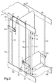
- the bearings 10 and 11 are via a toothed belt 12 coupled to each other, the toothed belt 12 via the deflection gears 13 and 14 to be led. While only one toothed belt 12 is shown in FIG. 3, those in FIG 3 rear bearing, for example the bearings attached to the slide bearing 20c, 20d, be connected to each other via a second toothed belt.
- the bearing 10 of the dancer roll 8 is biased downwards by a spring 25, whereby controlled slight film tension is achieved.
- 3 shows four sensors 17a, 17b, 17c and 17d which are used to detect the position of the second dancer roller 9 or its bearing 11 or the slide bearing 20b. If the sensor 17c detects the dancer roller 9 in its vicinity, the drive of the drivable supply roll holder can be accelerated and if the second sensor detects the dancer roller 9 from above 17b, the drive can be slowed down. If the sensor 17a or 17d detects, ie the sensor at the very top or the sensor at the very bottom the dancer roller 9, the device for producing film bags can be switched off as a whole.
- sensors can also be used to detect the position the dancer roll 8 may be provided. Sensors for detecting the rotation of the Deflection wheels 13, 14 or used to detect their current rotational position be to control the drive of the drivable supply roll holder, because with a Changing the position of the dancer rollers 8, 9, the deflection wheels 13, 14 are rotated.
- the Device comprises a first and second device for feeding film 2a, 2b, wherein the conveyor 4 conveys both foils 2a, 2b together.
- the device further comprises a film welding device for welding the films 2a, 2b Foil bags.
- the reference numerals used in the previous figures denote the same elements in FIG. 4, whereby for the first device for feeding of slide 2a an "a" is appended to the respective reference number and for the second Device for feeding film 2b a "b".
- the functioning and structure of the The first and second devices for feeding film are the same as those in FIGS. 1 to 3 shown devices, except that the conveyor 4 to both Devices for feeding foil are heard. A detailed description is therefore not necessary.
- the film 2a which is fed from the first device for feeding film, is through the conveyor 4 with the film 2b, which from the second device to Feeding film is fed, placed on top of each other.
- the foils laid on top of each other 2a, 2b are made by the welding device 24, which has one or more welding jaws includes, welded to foil bags. There can also be a between the foils 2a and 2b Bottom foil must be inserted so that stand-up foil pouches are produced.
- rollers 4 shown in FIG. 4 are not the conveying device, but (non-driven) Deflection rollers, the conveyor can also downstream of Welding device 24 may be arranged.
Landscapes
- Making Paper Articles (AREA)
- Controlling Rewinding, Feeding, Winding, Or Abnormalities Of Webs (AREA)
- Supplying Of Containers To The Packaging Station (AREA)
- Containers And Plastic Fillers For Packaging (AREA)
- Replacement Of Web Rolls (AREA)
- Advancing Webs (AREA)
- Registering, Tensioning, Guiding Webs, And Rollers Therefor (AREA)
- Processing And Handling Of Plastics And Other Materials For Molding In General (AREA)
Description
- Fig. 1
- eine schematische Darstellung einer Vorrichtung zum Zuführen von Folie,
- Fig. 2a und Fig. 2b
- je eine schematische Darstellung einer Foliensensoreinrichtung von einer Vorrichtung zum Zuführen von Folie,
- Fig. 3
- eine dreidimensionale schematische Darstellung einer Foliensensoreinrichtung von einer Vorrichtung zum Zuführen von Folie,
- Fig. 4
- eine schematische Darstellung einer Vorrichtung zum Herstellen von Folienbeuteln,
In Fig. 3 sind vier Sensoren 17a, 17b, 17c und 17d dargestellt, die zur Detektion der Position der zweiten Tänzerwalze 9 bzw. deren Lager 11 oder dem Gleitlager 20b dient. Detektiert der Sensor 17c die Tänzerwalze 9 in seiner Nähe so kann der Antrieb der antreibbaren Vorratsrollenhalterung beschleunigt werden und detektiert der zweite Sensor von oben 17b die Tänzerwalze 9, so kann der Antrieb verlangsamt werden. Detektiert der Sensor 17a oder 17d, d. h. der Sensor ganz oben bzw. der Sensor ganz unten die Tänzerwalze 9, kann die Vorrichtung zur Herstellung von Folienbeuteln insgesamt abgeschaltet werden.
Claims (11)
- Vorrichtung (1) zum Zuführen von Folie (2, 2a, 2b) zur Herstellung von Folienbeuteln mit:die zwischen der Vorratsrollenhalterung (3, 3a, 3b) und der Fördereinrichtung (4) angeordnet ist,mindestens einer mit einem Antrieb antreibbaren Vorratsrollenhalterungen (3, 3a, 3b)mindestens einer Fördereinrichtung (4), zum Fördern einer Folie (2, 2a, 2b) von einer Vorratsrolle (5, 5a, 5b), die in der Vorratsrollenhalterung (3, 3a, 3b) gehalten ist,mindestens einer Foliensensoreinrichtung (6, 6a, 6b),
die mindestens eine ortsfeste Umlenkwalze (7, 7a, 7b) und in beweglichen Lagerungen (10, 10a, 10b, 11, 11a,11b) gelagerte erste und zweite Tänzerwalze (8, 8a, 8b, 9, 9a, 9b) zum Umlenken der Folie (2, 2a, 2b) umfasst,
wobei die Foliensensoreinrichtung (6, 6a, 6b) zur Steuerung des Antriebs der Vorratsrollenhalterung (3a, 3b) in Abhängigkeit von dem Abstand der ersten und/oder der zweiten Tänzerwalze (8, 8a, 8b, 9, 9a, 9b) zu der Umlenkwalze (7, 7a, 7b) ausgebildet ist,
dadurch gekennzeichnet, dass
die Lagerungen (10, 10a, 10b, 11, 11a, 11b) der ersten und zweiten Tänzerwalze (8, 8a, 8b, 9, 9a, 9b) an wenigstens einer flexiblen über ein Umlenkrad (13, 13a, 13b, 14, 14a, 14b) geführten Aufhängung (12, 12a, 12b) aufgehängt und dadurch so miteinander gekoppelt sind, dass sich das Gewicht der ersten und zweiten Tänzerwalze (8, 8a, 8b, 9, 9a, 9b) zumindest teilweise kompensiert. - Vorrichtung nach Anspruch 1, dadurch gekennzeichnet, dass die erste Tänzerwalze (8, 8a, 8b) in einer nach oben offenen und die zweite Tänzerwalze (9, 9a, 9b) in einer nach unten offenen Folienschlaufe angeordnet ist.
- Vorrichtung nach Anspruch 1, dadurch gekennzeichnet, dass die erste Tänzerwalze (8, 8a, 8b) in einer nach unten offenen und die zweite Tänzerwalze (9, 9a, 9b) in einer nach oben offenen Folienschlaufe angeordnet ist.
- Vorrichtung nach einem der Ansprüche 1 bis 3, dadurch gekennzeichnet, dass die flexible Aufhängung (12, 12a, 12b) durch einen Riemen, Zahnriemen, Gummiriemen, eine Schnur, Litze, Kette, Band, Seil o. ä. gegeben ist.
- Vorrichtung nach einem der Ansprüche 1 bis 4, dadurch gekennzeichnet, dass die flexible Aufhängung (12, 12a, 12b) ein Zahnriemen und das Umlenkrad (13, 13a, 13b 14, 14a, 14b) ein Zahnrad ist.
- Vorrichtung nach einem der Ansprüche 1 bis 5, dadurch gekennzeichnet, dass zwischen der ersten und zweiten Tänzerwalze (8, 8a, 8b, 9, 9a, 9b) wenigstens zwei weitere ortsfeste Umlenkwalzen (15, 15a, 15b, 16, 16a, 16b) angeordnet sind.
- Vorrichtung nach einem der Ansprüche 1 bis 6, dadurch gekennzeichnet, dass zumindest eine der ersten und zweiten Tänzerwalze (8, 8a, 8b, 9, 9a, 9b) durch ein Gewicht, ein elastisches Vorspannungselement, eine Feder, einen Gummi oder Gummizug vorgespannt ist.
- Vorrichtung nach einem der Ansprüche 1 bis 7, dadurch gekennzeichnet, dass Sensoren (17a, 17b, 17c, 17d) zur Detektion der Position der ersten und/oder zweiten Tänzerwalze (8, 8a, 8b, 9, 9a, 9b) vorgesehen sind.
- Vorrichtung nach einem der Ansprüche 1 bis 8, dadurch gekennzeichnet, dass am Umlenkrad Sensoren zur Detektion der Position der Tänzerwalzen vorgesehen sind.
- Vorrichtung (23) zur Herstellung von Folienbeuteln mit:
einer Verschweißeinrichtung (24) zum Verschweißen von mindestens zwei Folien (2a,2b)
gekennzeichnet durch
wenigstens zwei Vorrichtungen nach einem der Ansprüche 1 bis 9 zum Zuführen der zwei Folien (2a,2b). - Vorrichtung nach Anspruch 10, dadurch gekennzeichnet, dass die Fördereinrichtung (4) zur Förderung beider Folien (2a,2b) ausgebildet ist.
Priority Applications (17)
| Application Number | Priority Date | Filing Date | Title |
|---|---|---|---|
| DK02026889T DK1428780T3 (da) | 2002-12-02 | 2002-12-02 | Apparat til tilförsel af folie til fremstilling af folieposer og apparat til fremstilling af folieposer |
| TR2004/02039T TR200402039T4 (tr) | 2002-12-02 | 2002-12-02 | Folyo torbalar imal etmek için folyo sevk etmeye yarayan tertibat ve folyo torbalar imal etmeye yarayan tertibat. |
| SI200230020T SI1428780T1 (en) | 2002-12-02 | 2002-12-02 | Device for feeding of film for the production of film bags and device for the production of film bags |
| AT02026889T ATE273228T1 (de) | 2002-12-02 | 2002-12-02 | Vorrichtung zum zuführen von folie zur herstellung von folienbeuteln und vorrichtung zur herstellung von folienbeuteln |
| EP02026889A EP1428780B1 (de) | 2002-12-02 | 2002-12-02 | Vorrichtung zum Zuführen von Folie zur Herstellung von Folienbeuteln und Vorrichtung zur Herstellung von Folienbeuteln |
| ES02026889T ES2225717T3 (es) | 2002-12-02 | 2002-12-02 | Dispositivo para el suministro de lamina para la fabricacion de bolsas de lamina y dispositivo para la fabricacion de bolsas de lamina. |
| DE50200831T DE50200831D1 (de) | 2002-12-02 | 2002-12-02 | Vorrichtung zum Zuführen von Folie zur Herstellung von Folienbeuteln und Vorrichtung zur Herstellung von Folienbeuteln |
| PT02026889T PT1428780E (pt) | 2002-12-02 | 2002-12-02 | Processo para fornecimento de folhas de plastico para a producao de sacos de folhas de plastico e dispositivo para a producao de sacos de folhas de plastico |
| TW092132196A TWI230674B (en) | 2002-12-02 | 2003-11-17 | Device for feeding foils for the manufacture of foil bags and device for the manufacture of foil bags |
| CA002450079A CA2450079C (en) | 2002-12-02 | 2003-11-19 | Device for feeding foils for the manufacture of foil bags and device for the manufacture of foil bags |
| KR1020030084407A KR100543085B1 (ko) | 2002-12-02 | 2003-11-26 | 포일 백의 제조를 위하여 포일을 공급하는 장치 및 포일백의 제조를 위한 장치 |
| US10/723,484 US7124798B2 (en) | 2002-12-02 | 2003-11-26 | Device for feeding foils for the manufacture of foil bags and device for the manufacture of foil bags |
| JP2003397192A JP2004182472A (ja) | 2002-12-02 | 2003-11-27 | フォイルバッグ製造用のフォイルを給送する装置、及びフォイルバッグ製造装置 |
| PL03363827A PL363827A1 (en) | 2002-12-02 | 2003-12-01 | Foil feeder for manufacturing plastic bags and system designed for manufacturing plastic bags |
| RU2003135519/12A RU2264346C2 (ru) | 2002-12-02 | 2003-12-01 | Устройство для подачи фольги, предназначенной для изготовления мешков, и устройство для изготовления мешков из фольги |
| BR0305328-8A BR0305328A (pt) | 2002-12-02 | 2003-12-02 | Dispositivo para alimentação de folhas de metal para a fabricação de sacos de folha de metal e dispositivo para fabricação de sacos de folha de metal |
| CNB2003101187394A CN100497138C (zh) | 2002-12-02 | 2003-12-02 | 用于供送制造箔袋用的箔的装置和用于制造箔袋的装置 |
Applications Claiming Priority (1)
| Application Number | Priority Date | Filing Date | Title |
|---|---|---|---|
| EP02026889A EP1428780B1 (de) | 2002-12-02 | 2002-12-02 | Vorrichtung zum Zuführen von Folie zur Herstellung von Folienbeuteln und Vorrichtung zur Herstellung von Folienbeuteln |
Publications (2)
| Publication Number | Publication Date |
|---|---|
| EP1428780A1 EP1428780A1 (de) | 2004-06-16 |
| EP1428780B1 true EP1428780B1 (de) | 2004-08-11 |
Family
ID=32319549
Family Applications (1)
| Application Number | Title | Priority Date | Filing Date |
|---|---|---|---|
| EP02026889A Expired - Lifetime EP1428780B1 (de) | 2002-12-02 | 2002-12-02 | Vorrichtung zum Zuführen von Folie zur Herstellung von Folienbeuteln und Vorrichtung zur Herstellung von Folienbeuteln |
Country Status (17)
| Country | Link |
|---|---|
| US (1) | US7124798B2 (de) |
| EP (1) | EP1428780B1 (de) |
| JP (1) | JP2004182472A (de) |
| KR (1) | KR100543085B1 (de) |
| CN (1) | CN100497138C (de) |
| AT (1) | ATE273228T1 (de) |
| BR (1) | BR0305328A (de) |
| CA (1) | CA2450079C (de) |
| DE (1) | DE50200831D1 (de) |
| DK (1) | DK1428780T3 (de) |
| ES (1) | ES2225717T3 (de) |
| PL (1) | PL363827A1 (de) |
| PT (1) | PT1428780E (de) |
| RU (1) | RU2264346C2 (de) |
| SI (1) | SI1428780T1 (de) |
| TR (1) | TR200402039T4 (de) |
| TW (1) | TWI230674B (de) |
Cited By (2)
| Publication number | Priority date | Publication date | Assignee | Title |
|---|---|---|---|---|
| CN103754419A (zh) * | 2014-01-23 | 2014-04-30 | 中达电通股份有限公司 | 一种枕式包装机及其控制方法 |
| CN108569576A (zh) * | 2018-06-22 | 2018-09-25 | 北京铂阳顶荣光伏科技有限公司 | 一种卷材开卷输送设备 |
Families Citing this family (19)
| Publication number | Priority date | Publication date | Assignee | Title |
|---|---|---|---|---|
| KR100954602B1 (ko) * | 2009-12-04 | 2010-04-26 | (주)세명정밀 | 원단 공급 장치 |
| JP5663924B2 (ja) * | 2010-03-31 | 2015-02-04 | 株式会社リコー | シート移送装置及び画像形成装置 |
| CN101823642B (zh) * | 2010-05-11 | 2011-12-21 | 浙江炜冈机械有限公司 | 浮动型自动张紧送料装置 |
| CN102408033A (zh) * | 2011-11-28 | 2012-04-11 | 南京工业职业技术学院 | 恒张力自动卷绕实训教学装置 |
| CN102544202B (zh) * | 2011-12-23 | 2015-02-04 | 常州天华新能源科技有限公司 | 晶体硅太阳能层压板eva薄膜智能敷设装置 |
| CN102756939A (zh) * | 2012-06-23 | 2012-10-31 | 武汉金运激光股份有限公司 | 一种带有张力调整装置的送料机 |
| CN102774679B (zh) * | 2012-08-01 | 2015-05-27 | 江阴市汇通包装机械有限公司 | 一种添底直立张力架 |
| KR102023581B1 (ko) | 2012-11-23 | 2019-09-24 | 해성디에스 주식회사 | 릴-투-릴 검사장치 및 릴-투-릴 검사방법 |
| JP5572239B1 (ja) * | 2013-03-08 | 2014-08-13 | 花王株式会社 | 搬送経路の転換装置 |
| CN103601023A (zh) * | 2013-11-14 | 2014-02-26 | 江苏闳业机械有限公司 | 智能控制储布机构 |
| CN105565038A (zh) * | 2014-10-13 | 2016-05-11 | 无锡市恒盛电机有限公司 | 自动浮动导向装置 |
| CN105129466B (zh) * | 2015-07-09 | 2018-01-16 | 长兴科恩德服装材料有限公司 | 一种衬布生产用放卷装置 |
| WO2018236389A1 (en) * | 2017-06-23 | 2018-12-27 | Kimberly-Clark Worldwide, Inc. | Tension regulating directly driven roller festoon |
| CN112074370B (zh) * | 2018-06-05 | 2023-03-14 | 伊雷克托科学工业股份有限公司 | 激光加工设备、其操作方法以及使用其加工工件的方法 |
| RU2711916C1 (ru) * | 2019-06-03 | 2020-01-23 | Закрытое акционерное общество "БЕСТРОМ" | Устройство для подачи ленточного материала |
| CN110328893A (zh) * | 2019-06-10 | 2019-10-15 | 温州润丰机械有限公司 | 一种编织袋内膜输送机 |
| CN111532861B (zh) * | 2020-05-07 | 2024-07-02 | 苏州红橙蓝机器人有限公司 | 柔性物料生产时用于控制张力的装置 |
| CN113511541A (zh) * | 2021-07-20 | 2021-10-19 | 施潘德包装印刷科技发展(北京)有限公司 | 一种烫金铝箔跳步控制设备 |
| CN116809769B (zh) * | 2023-07-20 | 2025-09-26 | 洛阳中清智能装备有限公司 | 一种金属箔材校直机辊盒纵向布置结构 |
Family Cites Families (13)
| Publication number | Priority date | Publication date | Assignee | Title |
|---|---|---|---|---|
| FR2214295A5 (de) * | 1973-01-11 | 1974-08-09 | Etudes De Machines Speciales | |
| US3934837A (en) * | 1974-10-04 | 1976-01-27 | Keiltex Corporation | Web winder and compensator apparatus |
| JPS5172054A (ja) | 1974-12-17 | 1976-06-22 | Fuji Photo Film Co Ltd | Chojakukatoseiobijobutsuo ruupujoni shusekisuru hoho oyobi sochi |
| JPS5233231A (en) | 1975-09-09 | 1977-03-14 | Koichi Matsushima | Construction off endless crawler for selt running painting machine, etc . |
| SE454584B (sv) * | 1982-04-13 | 1988-05-16 | Tetra Pak Ab | Anordning for bearbetning av en tubformig materialbana |
| DE3733780A1 (de) * | 1986-11-03 | 1988-05-19 | Windmoeller & Hoelscher | Vorrichtung zum aufwickeln von materialbahnen auf vorratsrollen |
| AT393372B (de) * | 1989-02-27 | 1991-10-10 | Kierner & Co Ohg | Vorrichtung fuer den laengsvorschub einer flexiblen warenbahn, insbesondere einer breiten papierbahn in einem plotter |
| JP2740415B2 (ja) | 1992-06-19 | 1998-04-15 | 三洋電機株式会社 | 匂い検知装置 |
| SE503620C2 (sv) * | 1994-02-14 | 1996-07-22 | Aplicator System Ab | Trådmatningsbuffert för matning av tråd |
| FI98355C (fi) * | 1995-02-24 | 1997-06-10 | Tuomo Halonen Oy | Laitteisto rainamateriaalin jatkosaumaamiseksi |
| US6003802A (en) * | 1998-04-03 | 1999-12-21 | Seagate Technology, Inc. | Tape leader pin assembly and method for making the same |
| DE19824798A1 (de) * | 1998-06-03 | 1999-12-09 | Indag Gmbh & Co Betriebs Kg | Vorrichtung und Verfahren zum Zuführen von Folien |
| US6050517A (en) * | 1998-09-22 | 2000-04-18 | Curt G. Joa | Counterbalanced web accumulator |
-
2002
- 2002-12-02 EP EP02026889A patent/EP1428780B1/de not_active Expired - Lifetime
- 2002-12-02 ES ES02026889T patent/ES2225717T3/es not_active Expired - Lifetime
- 2002-12-02 DE DE50200831T patent/DE50200831D1/de not_active Expired - Fee Related
- 2002-12-02 SI SI200230020T patent/SI1428780T1/xx unknown
- 2002-12-02 TR TR2004/02039T patent/TR200402039T4/xx unknown
- 2002-12-02 DK DK02026889T patent/DK1428780T3/da active
- 2002-12-02 AT AT02026889T patent/ATE273228T1/de not_active IP Right Cessation
- 2002-12-02 PT PT02026889T patent/PT1428780E/pt unknown
-
2003
- 2003-11-17 TW TW092132196A patent/TWI230674B/zh not_active IP Right Cessation
- 2003-11-19 CA CA002450079A patent/CA2450079C/en not_active Expired - Fee Related
- 2003-11-26 US US10/723,484 patent/US7124798B2/en not_active Expired - Fee Related
- 2003-11-26 KR KR1020030084407A patent/KR100543085B1/ko not_active Expired - Fee Related
- 2003-11-27 JP JP2003397192A patent/JP2004182472A/ja active Pending
- 2003-12-01 RU RU2003135519/12A patent/RU2264346C2/ru not_active IP Right Cessation
- 2003-12-01 PL PL03363827A patent/PL363827A1/xx unknown
- 2003-12-02 BR BR0305328-8A patent/BR0305328A/pt not_active IP Right Cessation
- 2003-12-02 CN CNB2003101187394A patent/CN100497138C/zh not_active Expired - Fee Related
Cited By (3)
| Publication number | Priority date | Publication date | Assignee | Title |
|---|---|---|---|---|
| CN103754419A (zh) * | 2014-01-23 | 2014-04-30 | 中达电通股份有限公司 | 一种枕式包装机及其控制方法 |
| CN103754419B (zh) * | 2014-01-23 | 2015-09-16 | 中达电通股份有限公司 | 一种枕式包装机及其控制方法 |
| CN108569576A (zh) * | 2018-06-22 | 2018-09-25 | 北京铂阳顶荣光伏科技有限公司 | 一种卷材开卷输送设备 |
Also Published As
| Publication number | Publication date |
|---|---|
| EP1428780A1 (de) | 2004-06-16 |
| CN1519183A (zh) | 2004-08-11 |
| RU2264346C2 (ru) | 2005-11-20 |
| DK1428780T3 (da) | 2004-10-04 |
| US20040178296A1 (en) | 2004-09-16 |
| KR100543085B1 (ko) | 2006-01-20 |
| DE50200831D1 (de) | 2004-09-16 |
| RU2003135519A (ru) | 2005-05-20 |
| CN100497138C (zh) | 2009-06-10 |
| SI1428780T1 (en) | 2005-02-28 |
| PT1428780E (pt) | 2004-10-29 |
| CA2450079A1 (en) | 2004-06-02 |
| PL363827A1 (en) | 2004-06-14 |
| ES2225717T3 (es) | 2005-03-16 |
| KR20040048305A (ko) | 2004-06-07 |
| BR0305328A (pt) | 2004-08-31 |
| TWI230674B (en) | 2005-04-11 |
| US7124798B2 (en) | 2006-10-24 |
| TW200409715A (en) | 2004-06-16 |
| JP2004182472A (ja) | 2004-07-02 |
| ATE273228T1 (de) | 2004-08-15 |
| TR200402039T4 (tr) | 2004-10-21 |
| CA2450079C (en) | 2005-09-13 |
Similar Documents
| Publication | Publication Date | Title |
|---|---|---|
| EP1428780A1 (de) | Vorrichtung zum Zuführen von Folie zur Herstellung von Folienbeuteln und Vorrichtung zur Herstellung von Folienbeuteln | |
| EP0144861B1 (de) | Vorrichtung zum zickzackförmigen Falten und Stapeln von Materialbahnen | |
| EP0968919B1 (de) | Vorrichtung zum Umwickeln von quaderförmigen Gegenständen mit einem Bahnförmigen Umwickelmaterial | |
| DE69301973T2 (de) | Vorrichtung zum Zuführen und Schneiden einer Folie zum Einwickeln von Gegenständen in einer Verpackungsmaschine | |
| DE1635429B2 (de) | Vorrichtung zum abwickeln eines stoffwickels | |
| DE10354348B4 (de) | Vielnadelkettenstichnähmaschine | |
| DE2659202B1 (de) | Vorrichtung zum Herstellen von Sackketten | |
| DE2809515C2 (de) | Vorrichtung zum Anbringen von Querschweißnähten an aufeinanderliegende Bahnen aus Kunststoffolie | |
| DE602004004447T2 (de) | Vorrichtung zum Umwickeln von gruppierten Gegenständen | |
| DE112014006623T5 (de) | Zuführungsband für eine Zuckerrohrerntemaschine | |
| DE69205213T2 (de) | Vorrichtung zur Zuführen einer endlosen Kunststoff-Folie. | |
| DE1552156C3 (de) | Geflechtrolle und Verfahren zu ihrer Herstellung | |
| DE60213148T2 (de) | Vorrichtung zum Formen eines Stapels von Artikellagen | |
| DE2123864C2 (de) | Verpackungsmaschine | |
| DE4001740C2 (de) | Vorrichtung zum Auslegen einer Warenbahn | |
| DE1265563C2 (de) | Maschine zum Herstellen offener Kunststoffsaecke | |
| DE2731838C2 (de) | Faltvorrichtung zum Zickzackfalten einer Endlosbahn | |
| DE102006051225B4 (de) | Vorrichtung und Verfahren zum Ablegen einer Materialbahn | |
| AT396100B (de) | Verfahren und vorrichtung zum herstellen einer federstruktur mit in umhuellungen angebrachten schraubenfedern | |
| EP2562110B1 (de) | Vorrichtung zur spannungsfreien Speicherung von bahnförmigem Material | |
| AT518269B1 (de) | Vorrichtung zur Herstellung eines Endlospapierverpackungsmaterials | |
| DE102012022992B3 (de) | Verfahren zum Herstellen eines Faltrollos | |
| DE1560052C (de) | Verfahren zur Herstellung eines Doppelvorhanges od.dgl. sowie Vorrichtung zur Durchführung des Verfahrens | |
| DE202007016849U1 (de) | Nähvorrichtung mit beweglichem Textilträger | |
| DE9014215U1 (de) | Verpackungsmaschine, insbesondere Banderoliermaschine |
Legal Events
| Date | Code | Title | Description |
|---|---|---|---|
| GRAP | Despatch of communication of intention to grant a patent |
Free format text: ORIGINAL CODE: EPIDOSNIGR1 |
|
| GRAS | Grant fee paid |
Free format text: ORIGINAL CODE: EPIDOSNIGR3 |
|
| PUAI | Public reference made under article 153(3) epc to a published international application that has entered the european phase |
Free format text: ORIGINAL CODE: 0009012 |
|
| 17P | Request for examination filed |
Effective date: 20030603 |
|
| AK | Designated contracting states |
Kind code of ref document: A1 Designated state(s): AT BE BG CH CY CZ DE DK EE ES FI FR GB GR IE IT LI LU MC NL PT SE SI SK TR |
|
| AX | Request for extension of the european patent |
Extension state: AL LT LV MK RO |
|
| GRAA | (expected) grant |
Free format text: ORIGINAL CODE: 0009210 |
|
| AK | Designated contracting states |
Kind code of ref document: B1 Designated state(s): AT BE BG CH CY CZ DE DK EE ES FI FR GB GR IE IT LI LU MC NL PT SE SI SK TR |
|
| AX | Request for extension of the european patent |
Extension state: AL LT LV MK RO |
|
| REG | Reference to a national code |
Ref country code: GB Ref legal event code: FG4D Free format text: NOT ENGLISH |
|
| REG | Reference to a national code |
Ref country code: CH Ref legal event code: NV Representative=s name: DIPL.-ING. HORST QUEHL PATENTANWALT Ref country code: CH Ref legal event code: EP |
|
| REG | Reference to a national code |
Ref country code: IE Ref legal event code: FG4D Free format text: GERMAN |
|
| GBT | Gb: translation of ep patent filed (gb section 77(6)(a)/1977) |
Effective date: 20040819 |
|
| REF | Corresponds to: |
Ref document number: 50200831 Country of ref document: DE Date of ref document: 20040916 Kind code of ref document: P |
|
| REG | Reference to a national code |
Ref country code: DK Ref legal event code: T3 |
|
| REG | Reference to a national code |
Ref country code: EE Ref legal event code: FG4A Ref document number: E000010 Country of ref document: EE Effective date: 20040816 |
|
| REG | Reference to a national code |
Ref country code: PT Ref legal event code: SC4A Free format text: AVAILABILITY OF NATIONAL TRANSLATION Effective date: 20040827 |
|
| REG | Reference to a national code |
Ref country code: SE Ref legal event code: TRGR |
|
| REG | Reference to a national code |
Ref country code: GR Ref legal event code: EP Ref document number: 20040403164 Country of ref document: GR |
|
| AKX | Designation fees paid |
Designated state(s): AT BE BG CH CY CZ DE DK EE ES FI FR GB GR IE IT LI LU MC NL PT SE SI SK TR |
|
| AXX | Extension fees paid |
Extension state: LV Payment date: 20030603 Extension state: MK Payment date: 20030603 Extension state: RO Payment date: 20030603 Extension state: LT Payment date: 20030603 Extension state: AL Payment date: 20030603 |
|
| REG | Reference to a national code |
Ref country code: ES Ref legal event code: FG2A Ref document number: 2225717 Country of ref document: ES Kind code of ref document: T3 |
|
| REG | Reference to a national code |
Ref country code: HK Ref legal event code: DE Ref document number: 1066778 Country of ref document: HK |
|
| ET | Fr: translation filed | ||
| REG | Reference to a national code |
Ref country code: HK Ref legal event code: GR Ref document number: 1066778 Country of ref document: HK |
|
| PLBE | No opposition filed within time limit |
Free format text: ORIGINAL CODE: 0009261 |
|
| STAA | Information on the status of an ep patent application or granted ep patent |
Free format text: STATUS: NO OPPOSITION FILED WITHIN TIME LIMIT |
|
| 26N | No opposition filed |
Effective date: 20050512 |
|
| PGFP | Annual fee paid to national office [announced via postgrant information from national office to epo] |
Ref country code: CH Payment date: 20081223 Year of fee payment: 7 Ref country code: CZ Payment date: 20081118 Year of fee payment: 7 Ref country code: DK Payment date: 20081218 Year of fee payment: 7 Ref country code: EE Payment date: 20081119 Year of fee payment: 7 Ref country code: IE Payment date: 20081227 Year of fee payment: 7 Ref country code: LU Payment date: 20081219 Year of fee payment: 7 Ref country code: MC Payment date: 20081216 Year of fee payment: 7 Ref country code: NL Payment date: 20081219 Year of fee payment: 7 Ref country code: TR Payment date: 20081202 Year of fee payment: 7 |
|
| PGFP | Annual fee paid to national office [announced via postgrant information from national office to epo] |
Ref country code: AT Payment date: 20081216 Year of fee payment: 7 Ref country code: ES Payment date: 20081215 Year of fee payment: 7 Ref country code: FI Payment date: 20081217 Year of fee payment: 7 Ref country code: PT Payment date: 20081120 Year of fee payment: 7 Ref country code: SK Payment date: 20081118 Year of fee payment: 7 |
|
| PGFP | Annual fee paid to national office [announced via postgrant information from national office to epo] |
Ref country code: SE Payment date: 20081217 Year of fee payment: 7 Ref country code: IT Payment date: 20081219 Year of fee payment: 7 Ref country code: BE Payment date: 20081218 Year of fee payment: 7 Ref country code: BG Payment date: 20081218 Year of fee payment: 7 |
|
| PGFP | Annual fee paid to national office [announced via postgrant information from national office to epo] |
Ref country code: FR Payment date: 20081211 Year of fee payment: 7 |
|
| PGFP | Annual fee paid to national office [announced via postgrant information from national office to epo] |
Ref country code: DE Payment date: 20090129 Year of fee payment: 7 |
|
| PGFP | Annual fee paid to national office [announced via postgrant information from national office to epo] |
Ref country code: GB Payment date: 20081217 Year of fee payment: 7 Ref country code: GR Payment date: 20081223 Year of fee payment: 7 Ref country code: SI Payment date: 20081120 Year of fee payment: 7 |
|
| PGFP | Annual fee paid to national office [announced via postgrant information from national office to epo] |
Ref country code: CY Payment date: 20081126 Year of fee payment: 7 |
|
| REG | Reference to a national code |
Ref country code: PT Ref legal event code: MM4A Free format text: LAPSE DUE TO NON-PAYMENT OF FEES Effective date: 20100602 |
|
| BERE | Be: lapsed |
Owner name: *INDAG G.- FUR INDUSTRIEBEDARF M.B.H. & CO. BETRIE Effective date: 20091231 |
|
| REG | Reference to a national code |
Ref country code: NL Ref legal event code: V1 Effective date: 20100701 |
|
| EUG | Se: european patent has lapsed | ||
| PG25 | Lapsed in a contracting state [announced via postgrant information from national office to epo] |
Ref country code: PT Free format text: LAPSE BECAUSE OF NON-PAYMENT OF DUE FEES Effective date: 20100602 Ref country code: MC Free format text: LAPSE BECAUSE OF NON-PAYMENT OF DUE FEES Effective date: 20100701 |
|
| REG | Reference to a national code |
Ref country code: CH Ref legal event code: PL |
|
| REG | Reference to a national code |
Ref country code: DK Ref legal event code: EBP |
|
| REG | Reference to a national code |
Ref country code: EE Ref legal event code: MM4A Ref document number: E000010 Country of ref document: EE Effective date: 20091231 |
|
| GBPC | Gb: european patent ceased through non-payment of renewal fee |
Effective date: 20091202 |
|
| PG25 | Lapsed in a contracting state [announced via postgrant information from national office to epo] |
Ref country code: CZ Free format text: LAPSE BECAUSE OF NON-PAYMENT OF DUE FEES Effective date: 20091202 Ref country code: SI Free format text: LAPSE BECAUSE OF NON-PAYMENT OF DUE FEES Effective date: 20091203 Ref country code: AT Free format text: LAPSE BECAUSE OF NON-PAYMENT OF DUE FEES Effective date: 20091202 Ref country code: FI Free format text: LAPSE BECAUSE OF NON-PAYMENT OF DUE FEES Effective date: 20091202 |
|
| REG | Reference to a national code |
Ref country code: SI Ref legal event code: KO00 Effective date: 20100708 |
|
| REG | Reference to a national code |
Ref country code: SK Ref legal event code: MM4A Ref document number: E 30 Country of ref document: SK Effective date: 20091202 |
|
| REG | Reference to a national code |
Ref country code: FR Ref legal event code: ST Effective date: 20100831 |
|
| REG | Reference to a national code |
Ref country code: IE Ref legal event code: MM4A |
|
| PG25 | Lapsed in a contracting state [announced via postgrant information from national office to epo] |
Ref country code: BE Free format text: LAPSE BECAUSE OF NON-PAYMENT OF DUE FEES Effective date: 20091231 Ref country code: NL Free format text: LAPSE BECAUSE OF NON-PAYMENT OF DUE FEES Effective date: 20100701 Ref country code: LI Free format text: LAPSE BECAUSE OF NON-PAYMENT OF DUE FEES Effective date: 20091231 Ref country code: IE Free format text: LAPSE BECAUSE OF NON-PAYMENT OF DUE FEES Effective date: 20091202 Ref country code: FR Free format text: LAPSE BECAUSE OF NON-PAYMENT OF DUE FEES Effective date: 20091231 Ref country code: EE Free format text: LAPSE BECAUSE OF NON-PAYMENT OF DUE FEES Effective date: 20091231 Ref country code: CY Free format text: LAPSE BECAUSE OF NON-PAYMENT OF DUE FEES Effective date: 20091202 Ref country code: CH Free format text: LAPSE BECAUSE OF NON-PAYMENT OF DUE FEES Effective date: 20091231 |
|
| PG25 | Lapsed in a contracting state [announced via postgrant information from national office to epo] |
Ref country code: DE Free format text: LAPSE BECAUSE OF NON-PAYMENT OF DUE FEES Effective date: 20100701 Ref country code: SK Free format text: LAPSE BECAUSE OF NON-PAYMENT OF DUE FEES Effective date: 20091202 Ref country code: BG Free format text: LAPSE BECAUSE OF NON-PAYMENT OF DUE FEES Effective date: 20100630 |
|
| PG25 | Lapsed in a contracting state [announced via postgrant information from national office to epo] |
Ref country code: GB Free format text: LAPSE BECAUSE OF NON-PAYMENT OF DUE FEES Effective date: 20091202 |
|
| PG25 | Lapsed in a contracting state [announced via postgrant information from national office to epo] |
Ref country code: DK Free format text: LAPSE BECAUSE OF NON-PAYMENT OF DUE FEES Effective date: 20100104 |
|
| REG | Reference to a national code |
Ref country code: ES Ref legal event code: FD2A Effective date: 20110325 |
|
| PG25 | Lapsed in a contracting state [announced via postgrant information from national office to epo] |
Ref country code: IT Free format text: LAPSE BECAUSE OF NON-PAYMENT OF DUE FEES Effective date: 20091202 |
|
| PG25 | Lapsed in a contracting state [announced via postgrant information from national office to epo] |
Ref country code: LU Free format text: LAPSE BECAUSE OF NON-PAYMENT OF DUE FEES Effective date: 20091202 |
|
| PG25 | Lapsed in a contracting state [announced via postgrant information from national office to epo] |
Ref country code: SE Free format text: LAPSE BECAUSE OF NON-PAYMENT OF DUE FEES Effective date: 20091203 |
|
| PG25 | Lapsed in a contracting state [announced via postgrant information from national office to epo] |
Ref country code: ES Free format text: LAPSE BECAUSE OF NON-PAYMENT OF DUE FEES Effective date: 20110314 |
|
| PG25 | Lapsed in a contracting state [announced via postgrant information from national office to epo] |
Ref country code: ES Free format text: LAPSE BECAUSE OF NON-PAYMENT OF DUE FEES Effective date: 20091203 |
|
| PG25 | Lapsed in a contracting state [announced via postgrant information from national office to epo] |
Ref country code: TR Free format text: LAPSE BECAUSE OF NON-PAYMENT OF DUE FEES Effective date: 20091202 |