EP1429032B1 - Compresseur centrifuge avec des aubes de guidage pour l'entrée - Google Patents
Compresseur centrifuge avec des aubes de guidage pour l'entrée Download PDFInfo
- Publication number
- EP1429032B1 EP1429032B1 EP03011358A EP03011358A EP1429032B1 EP 1429032 B1 EP1429032 B1 EP 1429032B1 EP 03011358 A EP03011358 A EP 03011358A EP 03011358 A EP03011358 A EP 03011358A EP 1429032 B1 EP1429032 B1 EP 1429032B1
- Authority
- EP
- European Patent Office
- Prior art keywords
- guide vanes
- inlet guide
- centrifugal compressor
- impeller
- flow passage
- Prior art date
- Legal status (The legal status is an assumption and is not a legal conclusion. Google has not performed a legal analysis and makes no representation as to the accuracy of the status listed.)
- Expired - Lifetime
Links
- 230000007423 decrease Effects 0.000 claims description 6
- 238000011144 upstream manufacturing Methods 0.000 description 14
- 230000002093 peripheral effect Effects 0.000 description 6
- 238000005452 bending Methods 0.000 description 4
- 230000003247 decreasing effect Effects 0.000 description 4
- 238000004891 communication Methods 0.000 description 2
- 230000001133 acceleration Effects 0.000 description 1
- 230000000694 effects Effects 0.000 description 1
- 230000002349 favourable effect Effects 0.000 description 1
- 230000006698 induction Effects 0.000 description 1
- 238000000034 method Methods 0.000 description 1
- 238000007789 sealing Methods 0.000 description 1
Images


Classifications
-
- F—MECHANICAL ENGINEERING; LIGHTING; HEATING; WEAPONS; BLASTING
- F04—POSITIVE - DISPLACEMENT MACHINES FOR LIQUIDS; PUMPS FOR LIQUIDS OR ELASTIC FLUIDS
- F04D—NON-POSITIVE-DISPLACEMENT PUMPS
- F04D27/00—Control, e.g. regulation, of pumps, pumping installations or pumping systems specially adapted for elastic fluids
- F04D27/02—Surge control
- F04D27/0246—Surge control by varying geometry within the pumps, e.g. by adjusting vanes
-
- F—MECHANICAL ENGINEERING; LIGHTING; HEATING; WEAPONS; BLASTING
- F04—POSITIVE - DISPLACEMENT MACHINES FOR LIQUIDS; PUMPS FOR LIQUIDS OR ELASTIC FLUIDS
- F04D—NON-POSITIVE-DISPLACEMENT PUMPS
- F04D29/00—Details, component parts, or accessories
- F04D29/40—Casings; Connections of working fluid
- F04D29/42—Casings; Connections of working fluid for radial or helico-centrifugal pumps
- F04D29/4206—Casings; Connections of working fluid for radial or helico-centrifugal pumps especially adapted for elastic fluid pumps
- F04D29/4213—Casings; Connections of working fluid for radial or helico-centrifugal pumps especially adapted for elastic fluid pumps suction ports
-
- F—MECHANICAL ENGINEERING; LIGHTING; HEATING; WEAPONS; BLASTING
- F04—POSITIVE - DISPLACEMENT MACHINES FOR LIQUIDS; PUMPS FOR LIQUIDS OR ELASTIC FLUIDS
- F04D—NON-POSITIVE-DISPLACEMENT PUMPS
- F04D29/00—Details, component parts, or accessories
- F04D29/40—Casings; Connections of working fluid
- F04D29/42—Casings; Connections of working fluid for radial or helico-centrifugal pumps
- F04D29/44—Fluid-guiding means, e.g. diffusers
- F04D29/46—Fluid-guiding means, e.g. diffusers adjustable
- F04D29/462—Fluid-guiding means, e.g. diffusers adjustable especially adapted for elastic fluid pumps
-
- F—MECHANICAL ENGINEERING; LIGHTING; HEATING; WEAPONS; BLASTING
- F05—INDEXING SCHEMES RELATING TO ENGINES OR PUMPS IN VARIOUS SUBCLASSES OF CLASSES F01-F04
- F05D—INDEXING SCHEME FOR ASPECTS RELATING TO NON-POSITIVE-DISPLACEMENT MACHINES OR ENGINES, GAS-TURBINES OR JET-PROPULSION PLANTS
- F05D2250/00—Geometry
- F05D2250/50—Inlet or outlet
- F05D2250/51—Inlet
Definitions
- the present invention relates to a centrifugal compressor, and more particular, to a centrifugal compressor, which uses inlet guide vanes to perform flow rate control.
- JP-A-56-115897 describes an example of a conventional centrifugal compressor having inlet guide vanes.
- the centrifugal compressor described in JP-A-56-115897 comprises a detector for detecting a discharge air pressure, a controller for finding a required angle of inclination of inlet guide vanes, and an actuator driven by a signal of the controller, in order that running at high efficiency is achieved by changing an angle of inclination of inlet guide vanes in response to pressure change in discharge air pressure to change a surge line of the compressor.
- JP-A-57-65898 describes another example of a conventional centrifugal compressor having inlet guide vanes.
- the centrifugal compressor described in JP-A-57-65898 comprises means for detecting the rotational speed of the compressor and means for detecting an air temperature, and the inlet guide vanes are driven on the basis of signals from these means to impart pre-whirl to an air flowing into the compressor to change the flow characteristics of the compressor.
- JP-A-11-62894 describes a further example of a conventional centrifugal compressor.
- the centrifugal compressor described in JP-A-11-62894 comprises one or more free rotors provided between inlet guide vanes and a centrifugal impeller, and the free rotors store therein flow energy to make running of the compressor further stable.
- the free rotors store therein kinetic energy to be able to prevent surging.
- the publication discloses nothing about a fear of generation of a situation, in which a large pressure difference is generated between upstream and downstream sides of inlet guide vanes to possibly give damage to the inlet guide vanes, at start-up, at which a suction pressure of a compressor becomes high, and does not describe cancellation of such disadvantages.
- DE-A-1 013 033 discloses a centrifugal compressor comprising an outer cylinder having an inner diameter being largest at the area where inlet guide vanes are arranged. An inner cylinder is not arranged in the suction flow passage.
- DE-A 821 879 describes a centrifugal compressor comprising an outer cylinder having an inner diameter decreasing in the direction of the inlet of the impeller.
- An inner cylinder is arranged coaxially within the outer cylinder.
- Guide vanes are attached at the end of a pin between the end face inner cylinder, the pin being slidably supported in the inner cylinder.
- the problem underlying the invention is to provide a centrifugal compressor avoiding damage to the inlet vanes even when the suction pressure and thus a load on the inlet guide vanes is increased.
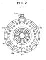
- FIGs. 1 and 2 are views showing an embodiment of a centrifugal compressor
- Fig. 1 is a longitudinal, cross sectional view
- Fig. 2 is a view viewed from an arrow A.
- a main shaft 100a of the centrifugal compressor is connected to a shaft of a driving machine (not shown) directly or through a speed-increasing gear.
- a centrifugal impeller 11a is mounted on a tip end of the main shaft 100a.
- a diffuser 101 which is defined by a side of a casing 42 and a side of an outer cylinder described in detail later is provided downstream of the centrifugal impeller 11a.
- the casing 42 receives therein bearings holding the main shaft 100a and shaft seal means.
- the diffuser 101 may be a ribbed diffuser, on which blades having a slight height in a widthwise direction of a flow passage as shown in the drawing are arranged at intervals in a circumferential direction, or a vaned diffuser, or a vaneless diffuser.
- a spiral-shaped scroll 102 is disposed downstream of the diffuser 101.
- the scroll 102 is defined by a part of an outer cylinder 14a and the casing 42.
- An inner peripheral surface of the outer cylinder 14a forms a cylindrical-shaped suction flow passage on a suction side of the impeller 11a.
- An inner cylinder 13a supported by stays 15a is arranged centrally of the suction flow passage.
- a tip end of the inner cylinder 13a assumes a streamline shape to reduce a flow resistance.
- Outer peripheral sides of the stays 15a are fixed to the outer cylinder 14a.
- the stays 15a are disposed in a plurality of positions spaced substantially equally in the circumferential direction.
- Inlet guide vanes 12a are arranged in the suction flow passage between the stays 15a and the impeller 11a and at a position to correspond to an intermediate portion of the inner cylinder 13a.
- the inlet guide vanes 12a are eleven in number in the embodiment and spaced equally in the circumferential direction.
- Rotating shafts 31 are provided on root sides of the inlet guide vanes 12a.
- the rotating shafts 31 are rotatably supported by bearings 16a, which are held on the outer cylinder 14a.
- An extended rotating shaft 17a which extends outside of the casing 42 and is rotatably supported by a bearing 16c held on the casing 42, is connected to the rotating shaft 31 for one inlet guide vane among the plurality of inlet guide vanes 12a.
- a radially extending arm 19a is attached to an end of the extended rotating shaft 17a extending outside of the casing 42. Meanwhile, arms 20a extending perpendicularly to the rotating shafts 31 are attached to intermediate portions of the rotating shafts 31 in the axial direction. Ends of the arms 20a are connected to a ring 18a through other arms 32.
- a pneumatic power device or the like (not shown) is used to rotatingly drive the arm 19a disposed outside the casing 42, the extended rotating shaft 17a and the rotating shaft 31 connected with the extended rotating shaft 17a are rotated, and the arm 20a attached to the rotating shaft 31 connected with the extended rotating shaft 17a turns the ring 18a around a rotational axis of the impeller 11a.
- the inlet guide vanes 12a configured in this manner are used to permit a working gas to flow into the impeller 11a at a predetermined flow angle.
- the working gas compressed by the impeller flows into the scroll 102 through the diffuser 101.
- the inlet guide vanes 12a are fully opened.
- the inlet guide vanes 12a are oriented in a flow direction.
- the inlet guide vanes 12a are turned to cause the working gas to have a whirl component. At this time, the suction flow passage is narrowed.
- the inlet guide vanes 12a used in controlling a flow rate of the centrifugal compressor have an advantage that normally efficiency is favorable at other points than an operating point and torque at startup can be decreased comparatively.
- the inlet guide vanes 12a cause whirling of a gas sucked into the centrifugal compressor in addition to flow rate control. When the sucked gas has a whirling component, work amount of the impeller 11a varies.
- u 2 designates a peripheral speed at an outlet of the impeller 11a
- u 1 designates a peripheral speed at an inlet of the impeller 11a
- v u2 designates a circumferential component of an absolute velocity of the working gas at the outlet of the impeller
- v u1 designates a circumferential component of an absolute velocity of the working gas at the inlet of the impeller
- g designates the gravitational acceleration.
- the use of the inlet guide vanes 12a makes it possible to decrease torque at startup.
- a centrifugal compressor is driven by an induction motor capable of running only at a fixed speed, there is a case which must reduce torque at startup of the centrifugal compressor by virtue of restriction on current value and voltage value.
- inlet gas temperature, gas pressure and gas density are higher at startup than in a steady state. In this case, it is necessary to decrease torque at startup. Since with the use of inlet guide vanes, whirling is imparted to a working gas and a cross sectional area around an inlet guide vane portion is reduced, a mass flow rate decreases to reduce a load on an impeller. Thereby, a compressor can be started up.
- the provision of the inlet guide vanes 12a makes it possible to start up a compressor even when temperature and pressure of a sucked gas are high, but pressure at the inlet of the impeller becomes smaller than the suction pressure. Thereby, a pressure difference is generated between upstream and downstream sides of the inlet guide vanes 12a and a load corresponding to the pressure difference is imposed on the inlet guide vanes 12a.
- a pressure difference between upstream and downstream sides of inlet guide vanes is 1 atmospheric pressure at maximum, and so a load on the inlet guide vanes is comparatively small.
- centrifugal compressors in which a suction pressure is several times to ten times or more as high as atmospheric pressure, however, an inlet guide vane portion is narrowed for the purpose of starting up the compressor, with the result that a pressure difference between upstream and downstream sides of inlet guide vanes becomes large, so that a load on the inlet guide vanes is greatly increased.
- both the outer cylinder 14a and the inner cylinder 13a are made larger in diameter around the inlet guide vanes 12a than at other areas.
- both the outer cylinder 14a and the inner cylinder 13a are gently decreased in outer diameter in an area running from the large-diameter area to the inlet of the impeller.
- a cross sectional area of the flow passage is increased in the embodiment, in which the outer cylinder 14a increases a cross sectional area of the flow passage and the inner cylinder 13a decreases a cross sectional area of the flow passage.
- an increase in diameter of the outer cylinder 14a can be made smaller than that of the inner cylinder 13a.
- a radial length L of the inlet guide vanes 12a obtained by subtracting the inner diameter of the inner cylinder 13a from the inner diameter of the outer cylinder 14a. Since the radial length L of the inlet guide vanes 12a is shortened, strength of the inlet guide vanes 12a can be set in that range, which can resist a pressure difference between upstream and downstream sides of the inlet guide vanes 12a, required at startup of the compressor. The reason for this is as follows.
- Those portions of the inlet guide vanes 12a are root portions of the inlet guide vanes 12a.
- a maximum bending stress in these portions is proportional to the radial length L of the inlet guide vanes 12a to the third power and inversely proportional to a thickness of the inlet guide vanes 12a to the third power.
- the inlet guide vanes 12a are increased in thickness, a flow sucked into the compressor is made turbulent, so that a nonuniform flow enters into the impeller 11a.
- the radial length L of the inlet guide vanes 12a is shortened.
- centrifugal compressor is suitable in the case where a pressure difference between the front and the back of inlet guide vanes is larger than that in the embodiment shown in Fig. 1. That is, the present embodiment is applied in the case where with only a change in a ratio of inner and outer diameters of a flow passage in an inlet guide vane portion, it is feared that a bending stress acting on inlet guide vanes is increased to make the inlet guide vanes incapable of resisting the pressure difference.
- inlet guide vanes are divided radially into a plurality of sections. Also, portions communicated to a downstream side from an upstream side are formed in portions of a cross section perpendicular to an axis of the suction flow passage and in the neighborhoods of cut-off points of the inlet guide vanes by the divided inlet guide vanes.
- the divided guide vanes 12c are arranged on an inner diameter side of the inlet guide vanes 12b.
- a projection in a direction perpendicular to an axis is made sector-shaped.
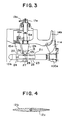
- both the inlet guide vanes 12b and the divided guide vanes 12c are positioned to extend along a flow direction Fin as shown in Fig. 4.
- the inlet guide vanes 12b are turned at startup to an angle, at which the suction flow passage is closed.
- the divided guide vanes 12c are turned to a different angle from that angle, to which the inlet guide vanes 12b are turned.
- the divided guide vanes 12c are mounted on an inner cylinder 13b.
- Rotating shafts 26 extending in a direction perpendicular to a rotating shaft 100a of an impeller 11a are arranged around a piston 23 within the inner cylinder 13b.
- Pinions 27 are mounted on the rotating shafts 26. Center positions of the rotating shafts 26 in a flow direction correspond to center positions of the inlet guide vanes 12b in the flow direction.
- Racks 28 adapted to mesh with the pinions 27 are mounted on the piston 23.
- An end of the piston 23 toward the impeller 11a is fitted into a sleeve 25 arranged in the inner cylinder 13b.
- An end of the piston 23 on a suction side is restrained to the inner cylinder by a spring 24.
- a hole 21 providing communication between the suction flow passage and an interior of the inner cylinder 13b is formed in a wall of the inner cylinder 13b at a position beyond the sleeve 25 toward the impeller 11a.
- Another hole 22 providing communication between the suction flow passage and the interior of the inner cylinder is formed in the wall of the inner cylinder 13b at a position, which corresponds to the spring 24.
- These holes 21, 22 are formed on upstream and downstream sides in the flow direction with respect to the divided guide vanes 12c.
- Pivot bearings are formed centrally on inner peripheral surfaces of the inlet guide vanes 12b, and pivots adapted to be fitted into the pivot bearings are formed centrally on outer peripheral surfaces of the divided guide vanes 12c.
- the inlet guide vanes 12b are turned as shown in Fig. 5 to shut off the suction flow passage. Since the suction flow passage is shut off, a pressure difference is generated between upstream and downstream sides of the inlet guide vanes 12b. The working gas flowing into the holes 22 and 21 produces a force corresponding to the pressure difference to move the piston 23 against the force of the spring 24. The racks 28 mounted on the piston 23 are moved to turn the pinions 27, thus separating the divided guide vanes 12c from the inlet guide vanes 12b. As a result, the suction flow passage is shifted from the shut-off state to be put in a state, in which slight openings are present.
- a centrifugal compressor Since a bending stress caused by pressure of the working gas acting on the inlet guide vanes is reduced, a centrifugal compressor can be improved in reliability even when a suction pressure is high. Also, it is possible to avoid surging of a centrifugal compressor.
Landscapes
- Engineering & Computer Science (AREA)
- Mechanical Engineering (AREA)
- General Engineering & Computer Science (AREA)
- Physics & Mathematics (AREA)
- Geometry (AREA)
- Structures Of Non-Positive Displacement Pumps (AREA)
Claims (3)
- Compresseur centrifuge comprenant :une roue centrifuge (11a) montée sur un arbre (100a) qui est relié à une machine d'entraînement ;un cylindre externe (14a) formant un passage d'écoulement d'aspiration en forme de cylindre sur un côté d'aspiration de la roue (11a) ;un cylindre interne (13a) agencé de manière radiale au centre du passage d'écoulement d'aspiration ; etune pluralité d'aubes directrices d'admission (12a) agencées dans le sens de la circonférence entre le cylindre interne (13a) et le cylindre externe (14a) dans une position correspondant à une partie intermédiaire du cylindre interne (13a), dans lequelle diamètre interne du cylindre externe (14a) et le diamètre externe du cylindre interne (13a) sont plus importants autour de ladite pluralité d'aubes directrices d'admission (12a) que dans d'autres zones et diminuent vers l'admission de la roue centrifuge (11a), et dans lequelladite pluralité d'aubes directrices d'admission (12a) ont des arbres tournants (31) qui sont réalisés sur les côtés d'emplantures de ces dernières.
- Compresseur centrifuge selon la revendication 1, caractérisé en ce que la zone de section transversale du passage d'écoulement d'aspiration perpendiculaire à l'axe du passage d'écoulement d'aspiration au niveau de la zone dans laquelle les aubes directrices d'admission (12a) sont agencées est supérieure à celle de l'admission de la roue (11a).
- Compresseur centrifuge selon la revendication 1 ou 2, caractérisé en ce que la pression d'un gaz de travail aspiré dans le compresseur centrifuge est d'au moins 1 MPa.
Applications Claiming Priority (2)
| Application Number | Priority Date | Filing Date | Title |
|---|---|---|---|
| JP2002358832 | 2002-12-11 | ||
| JP2002358832A JP4013752B2 (ja) | 2002-12-11 | 2002-12-11 | 遠心圧縮機 |
Publications (4)
| Publication Number | Publication Date |
|---|---|
| EP1429032A2 EP1429032A2 (fr) | 2004-06-16 |
| EP1429032A3 EP1429032A3 (fr) | 2004-06-30 |
| EP1429032B1 true EP1429032B1 (fr) | 2007-09-12 |
| EP1429032B8 EP1429032B8 (fr) | 2007-11-21 |
Family
ID=32322094
Family Applications (1)
| Application Number | Title | Priority Date | Filing Date |
|---|---|---|---|
| EP03011358A Expired - Lifetime EP1429032B8 (fr) | 2002-12-11 | 2003-05-19 | Compresseur centrifuge avec des aubes de guidage pour l'entrée |
Country Status (3)
| Country | Link |
|---|---|
| EP (1) | EP1429032B8 (fr) |
| JP (1) | JP4013752B2 (fr) |
| DE (1) | DE60316243T2 (fr) |
Cited By (1)
| Publication number | Priority date | Publication date | Assignee | Title |
|---|---|---|---|---|
| US11560900B2 (en) | 2020-06-09 | 2023-01-24 | Emerson Climate Technologies, Inc. | Compressor driveshaft assembly and compressor including same |
Families Citing this family (13)
| Publication number | Priority date | Publication date | Assignee | Title |
|---|---|---|---|---|
| US7975506B2 (en) | 2008-02-20 | 2011-07-12 | Trane International, Inc. | Coaxial economizer assembly and method |
| US9353765B2 (en) * | 2008-02-20 | 2016-05-31 | Trane International Inc. | Centrifugal compressor assembly and method |
| US8037713B2 (en) | 2008-02-20 | 2011-10-18 | Trane International, Inc. | Centrifugal compressor assembly and method |
| US7856834B2 (en) | 2008-02-20 | 2010-12-28 | Trane International Inc. | Centrifugal compressor assembly and method |
| ES2763334T3 (es) | 2012-10-09 | 2020-05-28 | Carrier Corp | Control de paletas de guía de entrada de compresor centrífugo |
| CN103133404A (zh) * | 2013-03-07 | 2013-06-05 | 江苏大学 | 长短叶片诱导轮前置预旋板的泵的结构设计 |
| CN104074805A (zh) * | 2014-07-22 | 2014-10-01 | 杭州福鼎节能科技服务有限公司 | 一种带双导叶轴向前导器的离心式通风机 |
| CN104806572B (zh) * | 2014-10-15 | 2017-07-07 | 湖南山水节能科技股份有限公司 | 一种带改变叶轮进水方向调节装置的可调泵 |
| US20160281736A1 (en) * | 2015-03-27 | 2016-09-29 | Dresser-Rand Company | Moveable inlet guide vanes |
| CN105413889A (zh) * | 2015-12-15 | 2016-03-23 | 宜兴市华鼎粮食机械有限公司 | 一种带可调向心泵的碟式离心机 |
| CN105822579B (zh) * | 2016-03-22 | 2017-11-03 | 中国石油大学(北京) | 一种离心泵前置导叶的自动调节方法及其装置 |
| CN108622872B (zh) | 2018-05-18 | 2020-09-29 | 国家能源投资集团有限责任公司 | 无定形碳材料及制备方法与用途 |
| IT202300022494A1 (it) * | 2023-10-26 | 2025-04-26 | Nuovo Pignone Tecnologie Srl | Turbomacchina con palette di guida all’ingresso migliorate |
Family Cites Families (6)
| Publication number | Priority date | Publication date | Assignee | Title |
|---|---|---|---|---|
| DE889091C (de) * | 1940-03-08 | 1953-09-07 | Versuchsanstalt Fuer Luftfahrt | Stetig verstellbares Leitschaufelsystem |
| DE821879C (de) * | 1950-02-11 | 1951-11-22 | Daimler Benz Ag | Drallblende zur Regelung des Ladedrucks an Ladegeblaesen von Brennkraftmaschinen |
| DE1013033B (de) * | 1954-03-17 | 1957-08-01 | Maschf Augsburg Nuernberg Ag | Verstelleitapparat fuer Geblaese |
| JPS56115897A (en) * | 1980-02-15 | 1981-09-11 | Mitsubishi Heavy Ind Ltd | Centrifugal compressor with inlet guide vanes |
| DE69010519T2 (de) * | 1989-02-02 | 1994-11-10 | Hitachi Ltd | Leitschaufel-Regler. |
| JPH0893682A (ja) * | 1994-09-22 | 1996-04-09 | Kobe Steel Ltd | 遠心圧縮機 |
-
2002
- 2002-12-11 JP JP2002358832A patent/JP4013752B2/ja not_active Expired - Fee Related
-
2003
- 2003-05-19 DE DE60316243T patent/DE60316243T2/de not_active Expired - Fee Related
- 2003-05-19 EP EP03011358A patent/EP1429032B8/fr not_active Expired - Lifetime
Cited By (1)
| Publication number | Priority date | Publication date | Assignee | Title |
|---|---|---|---|---|
| US11560900B2 (en) | 2020-06-09 | 2023-01-24 | Emerson Climate Technologies, Inc. | Compressor driveshaft assembly and compressor including same |
Also Published As
| Publication number | Publication date |
|---|---|
| JP2004190557A (ja) | 2004-07-08 |
| EP1429032A3 (fr) | 2004-06-30 |
| DE60316243D1 (de) | 2007-10-25 |
| EP1429032B8 (fr) | 2007-11-21 |
| JP4013752B2 (ja) | 2007-11-28 |
| DE60316243T2 (de) | 2008-06-05 |
| EP1429032A2 (fr) | 2004-06-16 |
Similar Documents
| Publication | Publication Date | Title |
|---|---|---|
| EP3043045B1 (fr) | Turbocompresseur avec compresseur centrifuge à compensation réglable | |
| EP3018355B1 (fr) | Compresseur centrifuge à compensation réglable et turbocompresseur muni de celui-ci | |
| US4082477A (en) | Compressor having two or more stages | |
| EP1429032A2 (fr) | Compresseur centrifuge avec des aubes de guidage pour l'entrée | |
| JP2975008B2 (ja) | 自由ロータ | |
| EP3534014A1 (fr) | Turbocompresseur doté d'un mécanisme de garniture réglable comprenant des réducteurs de vortex | |
| US10240613B2 (en) | Supersonic compressor with structural arrangement to increase pressure energy in a discharge process fluid received from a centrifugal impeller | |
| CN104067071B (zh) | 具有扩压器的变速多级离心式制冷压缩机 | |
| JP6128230B2 (ja) | 遠心圧縮機及び過給機 | |
| CN107304709A (zh) | 用于涡轮增压器的可调Trim的离心式压气机 | |
| EP2400156A2 (fr) | Ventilateur centrifuge à plusieurs étages | |
| CN107989804A (zh) | 双转子对转冲压压气机 | |
| JP2018510289A (ja) | プロセス流体を圧縮するための装置、システム、および方法 | |
| WO2019160550A1 (fr) | Compresseur centrifuge permettant d'obtenir un taux de compression élevé | |
| JP3557389B2 (ja) | 多段遠心圧縮機 | |
| WO2020263617A1 (fr) | Diffuseur supersonique sans aubes pour compresseur | |
| JP6763804B2 (ja) | 遠心圧縮機 | |
| JP2022094019A (ja) | 回転機械 | |
| CN113446260A (zh) | 叶轮以及离心压缩机 | |
| JP2018131986A (ja) | 圧縮機及び圧縮機の制御方法 | |
| EP3252316A1 (fr) | Diffuseur à géométrie variable | |
| JP2000205186A (ja) | 遠心圧縮機 | |
| JP2010236401A (ja) | 遠心形流体機械 | |
| WO2014149099A1 (fr) | Compresseur centrifuge avec sortie de roue à ailettes axiale | |
| EP3686439B1 (fr) | Compresseur centrifuge multi-étagé |
Legal Events
| Date | Code | Title | Description |
|---|---|---|---|
| PUAI | Public reference made under article 153(3) epc to a published international application that has entered the european phase |
Free format text: ORIGINAL CODE: 0009012 |
|
| PUAL | Search report despatched |
Free format text: ORIGINAL CODE: 0009013 |
|
| 17P | Request for examination filed |
Effective date: 20030519 |
|
| AK | Designated contracting states |
Kind code of ref document: A2 Designated state(s): AT BE BG CH CY CZ DE DK EE ES FI FR GB GR HU IE IT LI LU MC NL PT RO SE SI SK TR |
|
| AX | Request for extension of the european patent |
Extension state: AL LT LV MK |
|
| AK | Designated contracting states |
Kind code of ref document: A3 Designated state(s): AT BE BG CH CY CZ DE DK EE ES FI FR GB GR HU IE IT LI LU MC NL PT RO SE SI SK TR |
|
| AX | Request for extension of the european patent |
Extension state: AL LT LV MK |
|
| 17Q | First examination report despatched |
Effective date: 20041123 |
|
| AKX | Designation fees paid |
Designated state(s): DE IT |
|
| GRAP | Despatch of communication of intention to grant a patent |
Free format text: ORIGINAL CODE: EPIDOSNIGR1 |
|
| GRAS | Grant fee paid |
Free format text: ORIGINAL CODE: EPIDOSNIGR3 |
|
| GRAA | (expected) grant |
Free format text: ORIGINAL CODE: 0009210 |
|
| AK | Designated contracting states |
Kind code of ref document: B1 Designated state(s): DE IT |
|
| RAP2 | Party data changed (patent owner data changed or rights of a patent transferred) |
Owner name: HITACHI PLANT TECHNOLOGIES, LTD. |
|
| REF | Corresponds to: |
Ref document number: 60316243 Country of ref document: DE Date of ref document: 20071025 Kind code of ref document: P |
|
| RAP2 | Party data changed (patent owner data changed or rights of a patent transferred) |
Owner name: HITACHI PLANT TECHNOLOGIES, LTD. |
|
| PLBI | Opposition filed |
Free format text: ORIGINAL CODE: 0009260 |
|
| PLAB | Opposition data, opponent's data or that of the opponent's representative modified |
Free format text: ORIGINAL CODE: 0009299OPPO |
|
| PLAX | Notice of opposition and request to file observation + time limit sent |
Free format text: ORIGINAL CODE: EPIDOSNOBS2 |
|
| 26 | Opposition filed |
Opponent name: ATLAS COPCO ENERGAS GMBH Effective date: 20080612 Opponent name: SIEMENS AKTIENGESELLSCHAFT Effective date: 20080612 |
|
| PGFP | Annual fee paid to national office [announced via postgrant information from national office to epo] |
Ref country code: IT Payment date: 20080527 Year of fee payment: 6 |
|
| PGFP | Annual fee paid to national office [announced via postgrant information from national office to epo] |
Ref country code: DE Payment date: 20080722 Year of fee payment: 6 |
|
| PG25 | Lapsed in a contracting state [announced via postgrant information from national office to epo] |
Ref country code: DE Free format text: LAPSE BECAUSE OF NON-PAYMENT OF DUE FEES Effective date: 20091201 |
|
| PLAU | Termination of opposition procedure: information related to despatch of decision deleted |
Free format text: ORIGINAL CODE: EPIDOSDOPC1 |
|
| PLBD | Termination of opposition procedure: decision despatched |
Free format text: ORIGINAL CODE: EPIDOSNOPC1 |
|
| PG25 | Lapsed in a contracting state [announced via postgrant information from national office to epo] |
Ref country code: IT Free format text: LAPSE BECAUSE OF NON-PAYMENT OF DUE FEES Effective date: 20090519 |
|
| PLBD | Termination of opposition procedure: decision despatched |
Free format text: ORIGINAL CODE: EPIDOSNOPC1 |
|
| PLBM | Termination of opposition procedure: date of legal effect published |
Free format text: ORIGINAL CODE: 0009276 |
|
| STAA | Information on the status of an ep patent application or granted ep patent |
Free format text: STATUS: OPPOSITION PROCEDURE CLOSED |
|
| 27C | Opposition proceedings terminated |
Effective date: 20110220 |