EP1429040A1 - Verbindungsvorrichtung und damit ausgerüsteter Kabelkanal - Google Patents
Verbindungsvorrichtung und damit ausgerüsteter Kabelkanal Download PDFInfo
- Publication number
- EP1429040A1 EP1429040A1 EP03356189A EP03356189A EP1429040A1 EP 1429040 A1 EP1429040 A1 EP 1429040A1 EP 03356189 A EP03356189 A EP 03356189A EP 03356189 A EP03356189 A EP 03356189A EP 1429040 A1 EP1429040 A1 EP 1429040A1
- Authority
- EP
- European Patent Office
- Prior art keywords
- retaining
- wings
- locking shaft
- hole
- head
- Prior art date
- Legal status (The legal status is an assumption and is not a legal conclusion. Google has not performed a legal analysis and makes no representation as to the accuracy of the status listed.)
- Withdrawn
Links
- 239000002184 metal Substances 0.000 claims description 13
- 230000008878 coupling Effects 0.000 claims description 10
- 238000010168 coupling process Methods 0.000 claims description 10
- 238000005859 coupling reaction Methods 0.000 claims description 10
- 230000000295 complement effect Effects 0.000 claims description 4
- 125000006850 spacer group Chemical group 0.000 claims description 3
- 230000005489 elastic deformation Effects 0.000 claims description 2
- 238000009434 installation Methods 0.000 description 7
- 244000245420 ail Species 0.000 description 6
- 238000009423 ventilation Methods 0.000 description 3
- 241000287107 Passer Species 0.000 description 1
- 230000006978 adaptation Effects 0.000 description 1
- 230000000903 blocking effect Effects 0.000 description 1
- 238000000034 method Methods 0.000 description 1
Images

Classifications
-
- H—ELECTRICITY
- H02—GENERATION; CONVERSION OR DISTRIBUTION OF ELECTRIC POWER
- H02G—INSTALLATION OF ELECTRIC CABLES OR LINES, OR OF COMBINED OPTICAL AND ELECTRIC CABLES OR LINES
- H02G3/00—Installations of electric cables or lines or protective tubing therefor in or on buildings, equivalent structures or vehicles
- H02G3/26—Installations of cables, lines, or separate protective tubing therefor directly on or in walls, ceilings, or floors
- H02G3/263—Installation, e.g. suspension, of conduit channels or other supports
-
- F—MECHANICAL ENGINEERING; LIGHTING; HEATING; WEAPONS; BLASTING
- F16—ENGINEERING ELEMENTS AND UNITS; GENERAL MEASURES FOR PRODUCING AND MAINTAINING EFFECTIVE FUNCTIONING OF MACHINES OR INSTALLATIONS; THERMAL INSULATION IN GENERAL
- F16B—DEVICES FOR FASTENING OR SECURING CONSTRUCTIONAL ELEMENTS OR MACHINE PARTS TOGETHER, e.g. NAILS, BOLTS, CIRCLIPS, CLAMPS, CLIPS OR WEDGES; JOINTS OR JOINTING
- F16B21/00—Means for preventing relative axial movement of a pin, spigot, shaft or the like and a member surrounding it; Stud-and-socket releasable fastenings
- F16B21/02—Releasable fastening devices locking by rotation
Definitions
- the present invention relates to a device assembly of at least two sheet metal parts, as well as a assembly comprising sheet metal parts attached by minus such an assembly device.
- first and a second sheet metal part using at least one bolt which includes conventionally a screw and a nut.
- these pieces may respectively be a sheet metal chute of a cable tray and a support bracket for this cable tray cable. It takes a long time to install the bolt, since it requires the installation of the screw, then the screwing and finally tightening the bolt. Besides, then that it usually has to be repeated a lot of times for other bolts, this installation is frequently difficult to perform, especially when it requires working at height, in a awkward position.
- GB-A-1 139 976 is described the fixing of a element drilled on a support, using a fixing consisting of a body and a clamping rod. In a first step of this fixing, we mount the body on the support. Then, we place the element to fix against the support. Finally, install the clamping rod. Fixing by means of the device described in GB-A-1 139 976 therefore includes a number of steps which make it long to achieve.
- the invention therefore aims to facilitate assembly of two pieces.
- the invention also relates to a set comprising at least first and second sheet metal parts each of which is pierced with a hole, characterized in that it includes an assembly device as defined above, said retaining element passing through the drilled hole in the first room and in the hole drilled in the second part, the head of the retaining element retaining the first piece, the two wings of the retainer holding the second piece.
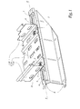
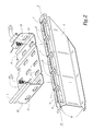
- a cable tray according to the invention is formed by a succession of chutes 1, only one of which is partially shown in Figures 1 and 2.
- two identical copies of an assembly device 2 according to the invention maintain assembled the chute 1 and a console 3 for supporting a section of the path of cables.
- the console 2 which is known per se, is a part in one piece, obtained by folding a sheet blank previously cut. It has a support part 4, which is elongated along a median axis A-A 'transverse to the chute 1 and on which this chute 1 rests. This support part 4 is pierced with holes 6 and 7, arranged alternately. Holes 6 are oblong and are placed in the extension of each other, so to extend along the median axis A-A '. Holes 7 allow mounting, according to a known arrangement, a chute in welded mesh, not shown.
- the console 2 ends laterally by means top and bottom of fixing 8, which allow its mounting on a rack, as described in the patent French No. 2,736,138.
- the chute 1 has a flat bottom 9, from which extend at right angles to two side walls 10. It is obtained in known manner by forming an elongated sheet, which has several longitudinal rows of holes ventilation slots 11, directed along the length of the chute 1.
- FIG 3 there is shown a single device assembly 2, which consists of two elements inseparable, namely a retaining element 12 and a locking shaft 13 pivotally mounted.
- the locking shaft 13 is symmetrical with respect to to its pivot axis X-X '. Before getting into the retaining element 12, this locking shaft 13 is as shown in Figure 4. One of its two ends, it then ends with a tubular portion 14, which extends a portion 15. Except at the level of two flats 16, this portion 15 is wider than the portion tubular 14, so that it defines a shoulder exterior 17.
- a groove 18 is formed between the portion 15 and a cam 19 defined by the locking shaft 13.
- the locking shaft 13 has a section transverse elongated in a direction B-B ' perpendicular to the pivot axis XX '.
- Cam 19 carries two lateral coupling bosses 20, each of which is, on the one hand, elongated in a direction parallel to the pivot axis X-X 'and, on the other hand, disposed at level of one of the two ends of the elongated section supra.
- the shaft of lock 13 ends with a hollow head coupling 21, which extends the cam 19.
- the internal cross sections and of the locking shaft 13 are generally hexagonal, so this locking shaft can be operated as well using a hexagon wrench not shown, engaged in the head 21, that using a pipe wrench not shown or a flat wrench not shown, engaged on this head 21.
- the head 21 delimits a slot 22, with which one can make pivot the locking shaft 13 using a screwdriver not shown.
- an axial hole 23 which has a cross section substantially hexagonal transverse, is provided in the portion 15 and opens inside the portion tubular 14.
- the retaining element 12 shown alone in the figure 5, consists of a shaped metal blank. It is substantially symmetrical about the pivot axis X-X 'of the locking shaft 13 and it has a head retaining elongate 24, as well as two retaining wings 25, facing each other and generally parallel to each other compared to each other. A fold 26 substantially at right angles connects each of the two long sides of the head 24 to one wings 25.
- the head 24 is pierced with a central hole 27, which is circular and intended for the passage of the tubular portion 14 of the locking shaft 13.
- This head 24 ends by two opposite end portions 28, each of which is provided with a support rim 29, extends a portion intermediate 30 of head 24 and is beyond two wings 25, on one side of the latter.
- Head 24 is provided with two stiffening flanges 31, each of which surrounds a hole 32 drilled in this head 24, straddling an end portion 28 and the intermediate portion 30.
- Each wing 25 has a portion 33 and a portion 34, which extends between the portion 33 and the head 24, from a fold 26.
- These portions 33 and 34 are substantially parallel to the pivot axis XX 'and are offset axially from each other. They are connected to each other by an oblique portion 35, so that they are also offset laterally from one another.
- the oblique portions 35 are oriented in such a way that the portions 33 of the same element 12 are closer to each other than are the portions 34 of this element 12. In other words, the space that the wings 25 of the same element 12 delimit between them is narrower at the level of the portions 33 than at the level of the portions 34.
- the retaining element 12 has a first width l measured in a direction parallel to its wings 25 and a second width L measured in a direction perpendicular to its wings 25. At the portions 34 which are substantially parallel to each other, this first width l and this second width L are substantially equal.
- Each portion 33 which extends from the end free of a wing 25, delimits an inner groove 36 which extends in a direction substantially parallel to the axis pivot X-X '.
- Each portion 34 carries several rows of notches snap-on exteriors 37, which are not all arranged at the same distance from the head 24, to allow a adaptation to a change in the thickness of the sheet chute 1 and / or the thickness of the console sheet 3. As we get closer to head 24, each snap notch 37 moves away from the portion 34 which door.
- the position of the shaft of locking 13 with respect to the retaining element 12 is such that the direction B-B 'passes between the two wings 25, which can therefore be compared to one of the other by elastic deformation of the retaining element 12.
- each assembly device 2 including the retaining element 12 and whose shaft lock 13 are positioned relative to each other as in figure 3, is inserted in a rectangle passage and more precisely square 39 formed by the intersection of a hole 6 and a ventilation hole 11.
- a or several snap notches 37 of this device assembly 2 cross part 4 of console 3.
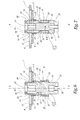
- this device assembly 2 is as in Figure 7.
- each shaft lock 13 Using a tool that can be operated manually as well being above the chute 1 and engaged in the hole axial 23 that by being below this chute 1 and by taken on or in the coupling head 21, which is advantageous, we then rotate each shaft lock 13, a quarter turn. It doesn't require the use of another tool to immobilize each element retainer 12, since the latter is blocked in rotation in a square passage 39, because the external face of each of its wings 25 applies to the edge of a hole 6 and that the lateral edges of each of its wings 25 are likely to abut against the edge of a hole ventilation 11.
- the assembly of the chute 1 and the console 3 using assembly devices 2 is a particularly simple operation to perform.
- the locking shaft 13 and the element of retainer 12 of the same assembly device 12 are already assembled and are therefore handled together when putting in place of this assembly device 2, so that this installation requires only one gesture.
- the complete assembly of an assembly device 2 does not require only one other gesture, particularly simple to perform, which involves rotating a quarter turn the locking shaft 13 of this assembly device 2.
- the assembly devices 2 have the advantage can be dismantled, which is why we apply the reverse procedure to that just detailed.
- an assembly device 2 is installed. Its bumps 20 and the walls delimiting its grooves 36 cooperate in the manner of coupling means complementary angularly blocking its tree of lock 13 in a position such as direction B-B ' associated with this tree 13 crosses each of the wings 25 of its retaining element 12.
- the cam 19 of the shaft of lock 13 spacer form between the two wings 25 of its retaining element 12 and maintains therebetween a distance greater than that which separates these two wings 25, when the locking shaft 13 is such that at the Figure 7. Not only does this cam 19 then prevent the bringing the two wings 25 towards each other, but in in addition it clamps each of these wings 25 on an edge of a hole 6.
- Two snap notches 37 on each wing 25 can come up against console 3, in order to oppose when removing the assembly device 2 if the shaft lock 13 has not been previously positioned as in Figure 7.
- grooves 36 can be replaced by slots in the wings 25.
Landscapes
- Engineering & Computer Science (AREA)
- Architecture (AREA)
- Civil Engineering (AREA)
- Structural Engineering (AREA)
- Connection Of Plates (AREA)
- Insertion Pins And Rivets (AREA)
Applications Claiming Priority (2)
| Application Number | Priority Date | Filing Date | Title |
|---|---|---|---|
| FR0215049A FR2847954A1 (fr) | 2002-11-29 | 2002-11-29 | Dispositif d'assemblage et chemin de cables en comportant application |
| FR0215049 | 2002-11-29 |
Publications (1)
| Publication Number | Publication Date |
|---|---|
| EP1429040A1 true EP1429040A1 (de) | 2004-06-16 |
Family
ID=32309849
Family Applications (1)
| Application Number | Title | Priority Date | Filing Date |
|---|---|---|---|
| EP03356189A Withdrawn EP1429040A1 (de) | 2002-11-29 | 2003-11-28 | Verbindungsvorrichtung und damit ausgerüsteter Kabelkanal |
Country Status (2)
| Country | Link |
|---|---|
| EP (1) | EP1429040A1 (de) |
| FR (1) | FR2847954A1 (de) |
Cited By (1)
| Publication number | Priority date | Publication date | Assignee | Title |
|---|---|---|---|---|
| EP2525457A1 (de) * | 2011-05-19 | 2012-11-21 | CTS Cable Tray Systems SAS | Vorrichtung zum Befestigen eines Abschnitts eines Kabelbaums auf einer Halterung, Kabelbaum, der eine solche Vorrichtung umfasst, und Verfahren zum Zusammenbau eines solchen Kabelbaums |
Citations (3)
| Publication number | Priority date | Publication date | Assignee | Title |
|---|---|---|---|---|
| GB1139976A (en) * | 1966-04-22 | 1969-01-15 | Carr Fastener Co Ltd | Two-part fastener for securing an apertured member to an apertured support |
| EP0715085A2 (de) * | 1994-10-27 | 1996-06-05 | Arturo Salice S.p.A. | Befestigungselement |
| EP0753275A1 (de) * | 1995-07-12 | 1997-01-15 | Franco Ferrari | Verbesserte Befestigungseinheit zur schnellen Befestigung von Beschlagteilen und Beschlagteile mit solch einer Befestigungseinheit |
-
2002
- 2002-11-29 FR FR0215049A patent/FR2847954A1/fr active Pending
-
2003
- 2003-11-28 EP EP03356189A patent/EP1429040A1/de not_active Withdrawn
Patent Citations (3)
| Publication number | Priority date | Publication date | Assignee | Title |
|---|---|---|---|---|
| GB1139976A (en) * | 1966-04-22 | 1969-01-15 | Carr Fastener Co Ltd | Two-part fastener for securing an apertured member to an apertured support |
| EP0715085A2 (de) * | 1994-10-27 | 1996-06-05 | Arturo Salice S.p.A. | Befestigungselement |
| EP0753275A1 (de) * | 1995-07-12 | 1997-01-15 | Franco Ferrari | Verbesserte Befestigungseinheit zur schnellen Befestigung von Beschlagteilen und Beschlagteile mit solch einer Befestigungseinheit |
Cited By (2)
| Publication number | Priority date | Publication date | Assignee | Title |
|---|---|---|---|---|
| EP2525457A1 (de) * | 2011-05-19 | 2012-11-21 | CTS Cable Tray Systems SAS | Vorrichtung zum Befestigen eines Abschnitts eines Kabelbaums auf einer Halterung, Kabelbaum, der eine solche Vorrichtung umfasst, und Verfahren zum Zusammenbau eines solchen Kabelbaums |
| FR2975541A1 (fr) * | 2011-05-19 | 2012-11-23 | Cts Cable Tray Systems Sas | Dispositif de fixation d'un troncon de chemin de cables sur un support, chemin de cables comprenant un tel dispositif et procede d'assemblage du chemin de cables |
Also Published As
| Publication number | Publication date |
|---|---|
| FR2847954A1 (fr) | 2004-06-04 |
Similar Documents
| Publication | Publication Date | Title |
|---|---|---|
| EP1241072B1 (de) | Verbindung eines Lenksäulenbügels mit einem Kraftfahrzeuglenkungsritzel | |
| FR2898164A1 (fr) | Attache munie d'un pied d'encliquetage a enfoncer au travers du trou d'un panneau | |
| FR3001006A1 (fr) | Article a fixer en aveugle sur un support | |
| EP3658790B1 (de) | Mutterkäfigsystem mit einem mutterkäfig und einem träger, auf dem der käfig montiert werden soll | |
| EP1138963B1 (de) | Haltevorrichtung für eine Bowdenzughülle | |
| EP0742329B1 (de) | Verriegelungsvorrichtung für Kraftwagenflügel mit verbesserten Einbaumitteln für Verkleidungskappe | |
| EP1429040A1 (de) | Verbindungsvorrichtung und damit ausgerüsteter Kabelkanal | |
| EP3434536B1 (de) | Befestigungsvorrichtung für ein gestängesystem zur betätigung von scheibenwischern | |
| EP0673806B1 (de) | Vorrichtung zum Befestigen von Stossstangen an der Karosserie eines Kraftfahrzeuges | |
| EP1320163B1 (de) | Immobilisierungszubehör für ein elektrisches Installationsgerät mit Direktschnappverbindung in einem Kabelrinnesockel | |
| EP2446155B1 (de) | Plastikmutter-befestigungvorrichtung | |
| EP1164676B1 (de) | Vorrichtung zur Befestigung eines elektrischen Geräts auf einem Kabelkanal | |
| FR2733285A1 (fr) | Dispositif de fixation mecanique rigide destine a une rotule, ensemble le comprenant et procedes de montage et demontage | |
| EP3375675B1 (de) | Abdeckung, verbindungsvorrichtung für die montage eines scheibenwischerblatts auf einem entsprechenden scheibenwischerarm, und entsprechendes scheibenwischsystem | |
| EP1258389B1 (de) | Verschlussvorrichtung für eine Öffnung zum Befestigen eines Gegenstandes, wie z.B. einen Kraftfahrzeugsitz | |
| EP2006553A1 (de) | Anordnung zum Befestigen eines Teils auf einem anderen | |
| EP2022921B1 (de) | Befestigungsvorrichtung für einen Mitnehmer einer Fensterscheibe bestehend aus Schraubenmuttern und Schrauben | |
| EP3442852B1 (de) | Anordnung einer abschirmung und eines karosserieelements eines kraftfahrzeugs, insbesondere eines karosserieelements aus blech | |
| EP1729019B1 (de) | Anordnung der Halterung einer Befestigungsmutter einer Komponente wie etwa ein Fahrzeugsitz | |
| EP2658057B1 (de) | Befestigungsvorrichtung zur Montage eines Elektrogeräteelements im Innern einer Öffnung in einer Einbauwand und Gesamtheit dieser Befestigungsvorrichtungen | |
| FR3008726A1 (fr) | Verrou pour portiere de vehicule automobile | |
| EP3807546A1 (de) | Nachgiebige plattenkante zur aufnahme einer mutterklemme | |
| EP1724124A1 (de) | Befestigungsring einer Radkappe an einem Rad und Verfahren dafür | |
| FR2662654A1 (fr) | Pare-chocs a fixation reglable pour vehicule automobile. | |
| EP2764188B1 (de) | Scharnieranordnung für die verbindung einer schwingtür eines kraftfahrzeugs |
Legal Events
| Date | Code | Title | Description |
|---|---|---|---|
| PUAI | Public reference made under article 153(3) epc to a published international application that has entered the european phase |
Free format text: ORIGINAL CODE: 0009012 |
|
| AK | Designated contracting states |
Kind code of ref document: A1 Designated state(s): AT BE BG CH CY CZ DE DK EE ES FI FR GB GR HU IE IT LI LU MC NL PT RO SE SI SK TR |
|
| AX | Request for extension of the european patent |
Extension state: AL LT LV MK |
|
| AKX | Designation fees paid | ||
| REG | Reference to a national code |
Ref country code: DE Ref legal event code: 8566 |
|
| STAA | Information on the status of an ep patent application or granted ep patent |
Free format text: STATUS: THE APPLICATION IS DEEMED TO BE WITHDRAWN |
|
| 18D | Application deemed to be withdrawn |
Effective date: 20041217 |