EP1429055A1 - Module intégral de contrôle de marche d'un véhicule automobile - Google Patents
Module intégral de contrôle de marche d'un véhicule automobile Download PDFInfo
- Publication number
- EP1429055A1 EP1429055A1 EP03293032A EP03293032A EP1429055A1 EP 1429055 A1 EP1429055 A1 EP 1429055A1 EP 03293032 A EP03293032 A EP 03293032A EP 03293032 A EP03293032 A EP 03293032A EP 1429055 A1 EP1429055 A1 EP 1429055A1
- Authority
- EP
- European Patent Office
- Prior art keywords
- lever
- rotation
- automatic
- control
- manual
- Prior art date
- Legal status (The legal status is an assumption and is not a legal conclusion. Google has not performed a legal analysis and makes no representation as to the accuracy of the status listed.)
- Granted
Links
- 230000006870 function Effects 0.000 claims description 31
- 230000008859 change Effects 0.000 claims description 15
- 230000007935 neutral effect Effects 0.000 claims description 13
- 239000012636 effector Substances 0.000 claims description 8
- 238000005096 rolling process Methods 0.000 claims description 7
- 238000013475 authorization Methods 0.000 claims description 2
- 230000005284 excitation Effects 0.000 claims description 2
- 230000007704 transition Effects 0.000 claims 1
- 238000010586 diagram Methods 0.000 description 6
- 230000008901 benefit Effects 0.000 description 3
- 238000009434 installation Methods 0.000 description 3
- 238000012546 transfer Methods 0.000 description 3
- 241001080024 Telles Species 0.000 description 2
- 238000006243 chemical reaction Methods 0.000 description 2
- 239000000470 constituent Substances 0.000 description 2
- 238000002513 implantation Methods 0.000 description 2
- RYGMFSIKBFXOCR-UHFFFAOYSA-N Copper Chemical group [Cu] RYGMFSIKBFXOCR-UHFFFAOYSA-N 0.000 description 1
- 230000006978 adaptation Effects 0.000 description 1
- 230000003416 augmentation Effects 0.000 description 1
- 210000001520 comb Anatomy 0.000 description 1
- 238000010276 construction Methods 0.000 description 1
- 229910052802 copper Inorganic materials 0.000 description 1
- 239000010949 copper Substances 0.000 description 1
- 238000013461 design Methods 0.000 description 1
- 238000006073 displacement reaction Methods 0.000 description 1
- 230000002349 favourable effect Effects 0.000 description 1
- 238000012423 maintenance Methods 0.000 description 1
- 238000004519 manufacturing process Methods 0.000 description 1
- 238000000034 method Methods 0.000 description 1
- 238000012986 modification Methods 0.000 description 1
- 230000004048 modification Effects 0.000 description 1
- 210000000056 organ Anatomy 0.000 description 1
- 238000003825 pressing Methods 0.000 description 1
- 230000008569 process Effects 0.000 description 1
- 230000009467 reduction Effects 0.000 description 1
- 238000013519 translation Methods 0.000 description 1
Images



Classifications
-
- B—PERFORMING OPERATIONS; TRANSPORTING
- B60—VEHICLES IN GENERAL
- B60K—ARRANGEMENT OR MOUNTING OF PROPULSION UNITS OR OF TRANSMISSIONS IN VEHICLES; ARRANGEMENT OR MOUNTING OF PLURAL DIVERSE PRIME-MOVERS IN VEHICLES; AUXILIARY DRIVES FOR VEHICLES; INSTRUMENTATION OR DASHBOARDS FOR VEHICLES; ARRANGEMENTS IN CONNECTION WITH COOLING, AIR INTAKE, GAS EXHAUST OR FUEL SUPPLY OF PROPULSION UNITS IN VEHICLES
- B60K20/00—Arrangement or mounting of change-speed gearing control devices in vehicles
- B60K20/02—Arrangement or mounting of change-speed gearing control devices in vehicles of initiating means
- B60K20/06—Arrangement or mounting of change-speed gearing control devices in vehicles of initiating means mounted on steering column or the like
-
- F—MECHANICAL ENGINEERING; LIGHTING; HEATING; WEAPONS; BLASTING
- F16—ENGINEERING ELEMENTS AND UNITS; GENERAL MEASURES FOR PRODUCING AND MAINTAINING EFFECTIVE FUNCTIONING OF MACHINES OR INSTALLATIONS; THERMAL INSULATION IN GENERAL
- F16H—GEARING
- F16H59/00—Control inputs to control units of change-speed- or reversing-gearings for conveying rotary motion
- F16H59/02—Selector apparatus
- F16H59/0204—Selector apparatus for automatic transmissions with means for range selection and manual shifting, e.g. range selector with tiptronic
-
- F—MECHANICAL ENGINEERING; LIGHTING; HEATING; WEAPONS; BLASTING
- F16—ENGINEERING ELEMENTS AND UNITS; GENERAL MEASURES FOR PRODUCING AND MAINTAINING EFFECTIVE FUNCTIONING OF MACHINES OR INSTALLATIONS; THERMAL INSULATION IN GENERAL
- F16H—GEARING
- F16H59/00—Control inputs to control units of change-speed- or reversing-gearings for conveying rotary motion
- F16H59/02—Selector apparatus
- F16H2059/0239—Up- and down-shift or range or mode selection by repeated movement
- F16H2059/0243—Up- and down-shift or range or mode selection by repeated movement with push buttons, e.g. shift buttons arranged on steering wheel
-
- F—MECHANICAL ENGINEERING; LIGHTING; HEATING; WEAPONS; BLASTING
- F16—ENGINEERING ELEMENTS AND UNITS; GENERAL MEASURES FOR PRODUCING AND MAINTAINING EFFECTIVE FUNCTIONING OF MACHINES OR INSTALLATIONS; THERMAL INSULATION IN GENERAL
- F16H—GEARING
- F16H59/00—Control inputs to control units of change-speed- or reversing-gearings for conveying rotary motion
- F16H59/02—Selector apparatus
- F16H59/0217—Selector apparatus with electric switches or sensors not for gear or range selection, e.g. for controlling auxiliary devices
-
- F—MECHANICAL ENGINEERING; LIGHTING; HEATING; WEAPONS; BLASTING
- F16—ENGINEERING ELEMENTS AND UNITS; GENERAL MEASURES FOR PRODUCING AND MAINTAINING EFFECTIVE FUNCTIONING OF MACHINES OR INSTALLATIONS; THERMAL INSULATION IN GENERAL
- F16H—GEARING
- F16H59/00—Control inputs to control units of change-speed- or reversing-gearings for conveying rotary motion
- F16H59/02—Selector apparatus
- F16H59/08—Range selector apparatus
- F16H59/10—Range selector apparatus comprising levers
- F16H59/105—Range selector apparatus comprising levers consisting of electrical switches or sensors
-
- F—MECHANICAL ENGINEERING; LIGHTING; HEATING; WEAPONS; BLASTING
- F16—ENGINEERING ELEMENTS AND UNITS; GENERAL MEASURES FOR PRODUCING AND MAINTAINING EFFECTIVE FUNCTIONING OF MACHINES OR INSTALLATIONS; THERMAL INSULATION IN GENERAL
- F16H—GEARING
- F16H61/00—Control functions within control units of change-speed- or reversing-gearings for conveying rotary motion ; Control of exclusively fluid gearing, friction gearing, gearings with endless flexible members or other particular types of gearing
- F16H61/24—Providing feel, e.g. to enable selection
Definitions
- This lever is currently connected to the gearbox via a cable.
- Such a mechanical bonding principle greatly reduces the possibilities of installation in the passenger compartment of the vehicle and requires a technical volume important minimum. Due to the limited installation possibilities, the above-mentioned controls are thus limited to areas of the passenger compartment of the vehicle few and / or not very interesting, in terms of services.
- the volume available in the cockpit area is limited in number of implantation areas. This is, in fact, as much space useful lost for the implementation of secondary commands, which are, consequently, distant from the driving position, such a distance having for distracting the driver from attention for too long of the vehicle.
- the device described by the above document is more particularly adapted to the actuation of a additional brake.
- this device implements a lever, the gear change being effected by rotation of a part of the device around the longitudinal axis of the lever.
- selecting a gear shift position speed involves operating the lever in a direction orthogonal to the axis longitudinal of it.
- Document DE 42 33 938 describes a device for controlling electronically controlled gear change for motor vehicle in which the change command is carried out by means of a lever mobile selection in rotation in two substantially orthogonal planes.
- the gearbox selection is carried out by moving the lever in a plane orthogonal to the plane for selecting parking positions P, reverse R, neutral N and forward gear D, (Drive), from the aforementioned forward gear position.
- the object of the present invention is to remedy all of the problems of the devices of the prior art used on current vehicles or proposed by the aforementioned documents.
- the integral module for running control of a motor vehicle relates to the implementation of a command electric grouping all the functions present on the vehicles current staff.
- Another object of the present invention is the implementation of a integral walking control module of a motor vehicle which can be installed on vehicles fitted with a controlled manual gearbox, BVMP, or an automatic gearbox, BVA.
- Another object of the present invention is the implementation of a integral module for controlling the operation of a motor vehicle, which, thanks to a volume much lower than the mechanical controls of the prior art, can be located in previously unusable areas, while allowing the grouping of functions and to improve both the ergonomics and safety offered to the driver and the portability or transfer from one range of vehicles to another, allowing Reduce costs significantly, thanks to better standardization.
- Another object of the present invention is the implementation of a integral module for controlling the operation of a motor vehicle, executed under the form of a commodo or lever, allowing the driver to access all the function commands of the current vehicles associated with the running of the vehicle and provide maximum accessibility benefits, comfort, maneuverability and passenger compartment volume.
- Another object of the present invention is the implementation of a integral module for controlling the operation of a motor vehicle capable of being advantageously located in the vicinity of the vehicle steering wheel, the driver, done, having the ability to access all of the functions associated with running the vehicle while keeping both hands on the steering wheel, which reduces the time the driver manipulates the controls, and, in make it more attentive to driving.
- Another object of the present invention is the implementation of a integral module for controlling the operation of a motor vehicle, the location of which specific, authorized by the integrality of the latter due to the grouping of all the current commands, allows, in addition, the release of the volume located between the front seats of the vehicle, volume occupied in current vehicles by the gearshift lever and / or by the handbrake, the volume thus freed up which can then advantageously be used to place, by example, a third front passenger, or, if necessary, improving comfort and safety of front passengers, especially during side impacts, by redistributing the volume available for the front seats of the vehicle.
- Another object of the present invention is, finally, the implementation of a integral module for controlling the operation of a motor vehicle by which, in due to the grouping of all the functions currently available, a simplification of the driving position of the vehicle can be implemented, following the reduction of all gearbox control members engine start speeds and barrel in one control module localized, easy to access and whose ergonomics, functionality and readability are, in consequently, improved.
- the integral walking control module of a motor vehicle, object of the present invention is remarkable in that it comprises a lever control comprising at least one control module for starting the engine of this motor vehicle and a control module of a gearbox automatic speed.
- the integral walking control module of a motor vehicle comprises a module, denoted M 1 , for controlling the starting of the engine of the motor vehicle and another module M 2 for controlling an automatic gearbox, as shown in the above figure.
- control modules M 1 and M2 for starting the engine respectively for the automatic gearbox control are associated to constitute in fact a commodo, which, in the nonlimiting example of implementation represented in FIG. 1, is mounted in the vicinity the steering wheel of the motor vehicle and, in particular, the steering column and the steering column sheath thereof.
- the aforementioned commodo consists of a lever with which different elements are associated to perform the vehicle engine start control and control of the automatic gearbox of the latter.
- the control lever is movable in rotation about its longitudinal axis, the axis Z'Z in FIG. 1, and, to ensure the function of controlling the starting of the engine , the module M 1 comprises at least circuits for detecting a plurality of discrete rotational positions of the control lever, that is to say of the commodo, relative to a reference position.
- the passage from the reference position, also called stop position, to the rolling position, then to the starting position is effected by manual rotation of the lever around its longitudinal axis Z'Z above, in the same direction of rotation, and the return from the unstable starting position or metastable to the driving position is performed by automatic recall in the reverse direction of rotation.
- the passage from the stop or reference position to the driving position can be performed by a 90 ° angle rotation for example, while the passage of the driving position, stable position, starting position, unstable position or metastable, can be performed by rotation in the same direction of rotation of a angle of 30 ° for example.
- control module of an automatic gearbox advantageously comprises a reverse gear selection system R, an automatic driving selection system or manual D, a neutral selection system N, an automatic gear change mode selection system A and a manual gear change mode selection system M + , M - .
- the automatic speed change mode selection system A and manual M + , M - advantageously comprises a push button with two positions for each of the selected functions, change of automatic speeds A, manual M + respectively M - .
- the passage from one to the other of the positions is carried out manually by a force exerted in a direction substantially parallel to the longitudinal axis Z'Z of the lever or commodo.
- the character of mobility in rotation of the commodo or lever in a plane containing the longitudinal axis of symmetry of the latter, advantageously corresponds to an orthogonal plane substantially to the longitudinal axis of the steering column not shown in drawings.
- positions such as center position, first position lateral and second lateral position mentioned above are preferably contained in the plane containing the longitudinal axis Z'Z of the commodo orthogonal to the longitudinal axis from the steering column, we understand that, however, the course of the commodo to reach the central positions, first lateral position and second position above mentioned side may correspond to a path outside the above plan, this path being represented in FIG. 2B for example, which represents a detail of the path shown in Figure 1.
- the dimensions x , y and z which represent the effective path of the longitudinal axis of the commodo Z'Z and, ultimately, of the commodo itself for pass from the stable central position, neutral position N, to one of the first respectively second stable lateral positions corresponding to an automatic or manual driving selection position D respectively to a reverse gear selection position R may correspond to line segments of length x , y and z of a few tens of millimeters.
- the systems for detecting a plurality of positions in discrete rotation and the selection system constituting the control module of an automatic gearbox, as well as the articulation module in rotation of the lever or commodo in a plane containing the longitudinal axis Z'Z of symmetry of the latter comprises, of course, effector means, that is to say, ultimately, electronic transducers, which deliver, on excitation generated by the position in rotation of the lever around its longitudinal axis Z'Z by the position of the push buttons A, M + , M- or respectively by the position in rotation of the lever in a plane containing the longitudinal axis Z'Z of symmetry of the lever, a coded numerical value representative of the position and of the state of selection of the previously mentioned control lever or commodo.
- the commodo when the commodo is placed near the steering wheel, the commodo or lever is substantially orthogonal to the axis of the steering column of the vehicle.
- the commodo acts directly on the control elements of the vehicle gearbox through the aforementioned effectors or transducers.
- center of rotation C of the commodo in the plane orthogonal to the axis of the steering column represents symbolically any member of relative rotation of the commodo with respect to the axis longitudinal of the aforementioned steering column, a body known as such.
- binary information is returned at the output of the electrical circuits or effectors equipping the latter. This binary information is then communicated to a card electronics responsible for controlling the power circuit of the gearbox and, thus, engage the report actually selected.
- the commodo object of the present invention also ensures, particularly advantageously, a role of restitution of effort.
- the effort restitution systems are then advantageously constituted by ball systems, springs, as well as by the ramp necessary for the realization of the aforementioned race / effort laws.
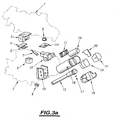
- the commodo object of the invention is mounted at the top of the steering column through the upper housing 1 and of the lower housing 2, as shown in Figures 3A and 3B for example.
- the keys are mounted in a key holder, item 18, which ensures their guidance and their maintenance to ensure their function of switching.
- the above keys operate microswitches placed on the selection printed circuit M / A bearing the reference 15. This printed circuit of M / A selection is integral with the key support 18.
- the stroke / effort law is that microswitches.
- a lever carrying the reference 16 constitutes the main part of the whole of the commodo.
- the room above contains housings for rotation cams bearing the reference 14, which allow the restitution of effort during the maneuver, that is to say the rotation of the commodo around its longitudinal axis of symmetry Z'Z to ensure the stop / run / start selection.
- the lever 16 is then blocked in translation by the finger support 12 shown in FIG. 3A, this finger support being integral with the axis 13.
- the lever 16 is however free to rotate, which ensures freedom of rotation of the commodo around the Z'Z axis.
- the axis 13 previously cited also has the function of maintaining a spring and two balls which ensure the restitution of forces.
- the switching function is then provided by the selection printed circuit M + / M - / stop / start bearing the reference 15, which is held on the key support 18.
- This printed circuit is a double-sided printed circuit, for example, and has angular tracks under its underside brought into contact by means of a spring contact micro-housing, designated sliding micro-element bearing the reference 17.
- Figure 3D represents the assembly of the printed circuit M + / M- / stop / start marked 15 on the base of the key holder 18.
- the operating kinematics is then represented physically by the grid 3, which, as shown in FIG. 3A, is fixed to the housing superior with the reference 1.
- the grid 3 includes then a groove reproducing the operating kinematics of the commodo, such as shown in Figure 2B, as described above in the description.
- the vertical component is formed of finger support 12, which keeps the axis 13 fixed.
- the latter is rotated by relative to the pivot support 10.
- the cover 11 is screwed onto the pivot support 10.
- the horizontal rotation component to ensure the kinematics shown in Figure 2B, is provided by two pivots referenced 8 and 9 in the upper and lower housings. These two pivots are fixed on the pivot support 10.
- the finger support 12 also holds the finger 7, which ensures the restitution of effort and guidance of the commodo according to the selection kinematics R, N, D positions, as shown in Figure 2B through the grid 3.
- the switching function due to the selection of positions R, N, D, as shown in FIG. 2B, is then produced by a printed circuit of RND selection bearing the reference 4, which is fixed on the grid 3. It includes angular tracks brought into contact by a sliding member 5 screwed onto the support sliding element 6.
- the electrical architecture of the control circuits does not require any consumption of current due to the fact that the actual control is ensured by simple voltage switching.
Landscapes
- Engineering & Computer Science (AREA)
- Mechanical Engineering (AREA)
- General Engineering & Computer Science (AREA)
- Chemical & Material Sciences (AREA)
- Combustion & Propulsion (AREA)
- Transportation (AREA)
- Arrangement Or Mounting Of Control Devices For Change-Speed Gearing (AREA)
- Control Of Throttle Valves Provided In The Intake System Or In The Exhaust System (AREA)
- Control Of Transmission Device (AREA)
- Mechanical Control Devices (AREA)
Abstract
Description
- a : sélecteur de sens : marche avant, neutre, marche arrière, généralement assuré par un levier à commande mécanique ;
- b : changement des rapports de boíte : assuré en mode manuel par un levier mécanique, souvent commun à la fonction sélecteur de sens, ou par des boutons poussoirs électriques disposés au niveau du volant ;
- c : démarrage moteur : commandé entre une position d'arrêt "OFF" et une position de contact "ON", soit par un bouton poussoir, soit par la rotation d'un barillet de démarrage, déverrouillée par une clé de contact, par commande exclusivement électrique.
- toutes les fonctions mises en oeuvre par l'intermédiaire d'une commande mécanique sont sujettes à de fortes contraintes de conception et de réalisation architecturales.
- la figure 1 représente, à titre illustratif, un schéma général, des éléments fonctionnels mis en oeuvre par le module intégral de contrôle de marche d'un véhicule automobile objet de la présente invention ;
- la figure 2A représente, à titre illustratif, un mode de mise en oeuvre spécifique non limitatif du module de commande de démarrage du moteur du véhicule automobile ;
- la figure 2B représente, à titre illustratif, un mode de mise en oeuvre spécifique non limitatif du module de commande d'une boíte de vitesse automatique équipant le module intégral de contrôle de marche d'un véhicule automobile conforme à l'objet de la présente invention ;
- la figure 3A représente une vue éclatée montrant l'agencement relatif des différentes pièces constitutives du module intégral de commande de la marche d'un véhicule automobile, conforme à l'objet de la présente invention ;
- la figure 3B représente, à titre illustratif, une vue éclatée montrant le détail de l'agencement relatif des différentes pièces constitutives d'un module de sélection de mode de changement de vitesse automatique et manuel, telles qu'illustrées en figure 3A ;
- la figure 3C représente, à titre illustratif, une vue éclatée montrant le détail de l'agencement relatif des différentes pièces constitutives d'un module de commande du démarrage moteur, entre les positions arrêt, roulage et démarrage ;
- la figure 3D représente, à titre illustratif, un montage spécifique d'un élément de commutation, sur le support de touches des module de changement de vitesse et de commande d'une boíte de vitesse automatique formant un commodo, conforme à l'objet de la présente invention ;
- la figure 3E représente, à titre illustratif, une vue éclatée montrant le détail de l'agencement relatif des différentes pièces permettant la mise en rotation du commodo objet de l'invention, tel que représenté en figures 3A à 3D, lors de la sélection de la marche arrière (R), du roulage automatique ou manuel (D) ou de l'arrêt neutre (N) ;
- la figure 3F représente, à titre illustratif, en vue éclatée, un montage spécifique d'un élément de commutation permettant d'assurer la sélection de la marche arrière (R), du roulage automatique ou manuel (D) ou de l'arrêt, neutre (N) et des pièces correspondantes, telles qu'illustrées en figure 3E ;
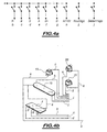
- la figure 4A représente, à titre purement illustratif, un schéma des connexions électriques et logiques de l'ensemble des fonctions de marche du véhicule commandées grâce à la mise en oeuvre d'un commodo conforme à l'objet de la présente invention ;
- la figure 4B représente, à titre illustratif, un schéma des connexions électriques physiques mises en oeuvre conformément au schéma de la figure 4A.
- la position de référence, position stable, correspondant à la position d'arrêt du véhicule automobile ;
- une position de roulage stable correspondant à une autorisation de déplacement du véhicule ;
- et enfin une position de démarrage instable ou, à tout le moins métastable, correspondant à un lancement du moteur du véhicule.
- une position centrale correspondant à une position de sélection du neutre N ;
- une première position latérale à la position centrale correspondant à une position de sélection du roulage automatique ou manuel D ; et
- une deuxième position latérale à la position centrale et sensiblement symétrique à la première position latérale vis-à-vis de la position centrale. Cette deuxième position latérale correspond à une position de sélection de la marche arrière R.
- 1: Boítier supérieur
- 2: Boítier inférieur
- 3 : Grille
- 4: Circuit imprimé de sélection RND
- 5: Elément glissant
- 6: Support d'élément glissant
- 7: Doigt
- 8: Pivot inférieur
- 9: Pivot supérieur
- 10 : Support de pivot
- 11 : Couvercle
- 12: Support de doigt
- 13: Axe
- 14 : Cames de rotation
- 15: Circuit imprimé de sélection M/A
- 16 : Levier
- 17 : Micro-élément glissant
- 18: Support de touches ou bouton poussoir
- 19: Touche M+
- 20: Touche M/A
- 21 : Touche M-
- la sélection du mode de roulage, position PARK, position REVERSE, position NEUTRE, position DRIVE. La position PARK n'est pas présente dans tous les cas de figure lorsque, par exemple, le véhicule est équipé d'une boíte à vitesses de type BVMP ;
- la sélection du type de roulage automatique en position D ou manuel M ;
- le changement de rapport de boíte en manuel par impulsion ;
- le démarrage moteur, position moteur arrêté, position contact, position moteur démarré ;
- augmentation de la consigne respectivement diminution de la consigne obtenues par appui du bouton correspondant.
Claims (8)
- Module intégral de contrôle de marche d'un véhicule automobile, caractérisé en ce qu'il comporte un levier de commande comportant au moins des moyens de commande (M1) de démarrage du moteur, et des moyens de commande (M2) d'une boíte de vitesses automatique, associés pour constituer un commodo, ledit commodo étant constitué sous forme d'un levier pour exécuter respectivement les fonctions de commande de démarrage par rotation manuelle du levier autour de son axe longitudinal de symétrie et de commande de boíte de vitesses automatique par rotation dudit levier dans un plan contenant l'axe longitudinal de symétrie.
- Module selon la revendication 1, caractérisé en ce que ledit levier de commande étant mobile en rotation autour de son axe longitudinal, lesdits moyens de commande du démarrage du moteur comprennent au moins des moyens de détection d'une pluralité de positions en rotation discrètes dudit levier de commande par rapport à une position de référence, ladite pluralité de positions en rotation discrètes comportant au moins :ladite position de référence, stable, correspondant à la position d'arrêt dudit véhicule automobile ;une position de roulage, stable, correspondant à une autorisation de déplacement du véhicule ;une position de démarrage, instable, correspondant à un lancement du moteur du véhicule, le passage de la position de référence à la position de roulage puis à la position de démarrage étant effectué par rotation manuelle dudit levier dans un même sens de rotation et le retour de la position de démarrage, instable, à la position de roulage étant effectué par rappel automatique dans le sens de rotation inverse, le retour de la position de roulage à la position d'arrêt étant effectué par rotation manuelle dans le sens de rotation inverse.
- Module selon la revendication 1 ou 2, caractérisé en ce que lesdits moyens de commande d'une boíte de vitesse automatique comprennent au moins :un moyen de sélection de marche arrière (R) ;un moyen de sélection de roulage automatique ou manuel (D) ;un moyen de sélection de neutre (N) ;un moyen de sélection de mode de changement de vitesse automatique (A) ;un moyen de sélection de mode de changement de vitesse manuel (M+, M-).
- Module selon la revendication 3, caractérisé en ce que lesdits moyens de sélection de mode de changement de vitesse automatique (A) et manuel (M+, M-) comportent un bouton poussoir à deux positions, le passage de l'une à l'autre desdites positions étant réalisé manuellement par un effort exercé dans une direction sensiblement parallèle à l'axe dudit levier.
- Module selon la revendication 3 ou 4, caractérisé en ce que lesdits moyens de sélection de marche arrière (R) de roulage automatique ou manuel (D) et de sélection de neutre (N) comportent :des moyens d'articulation en rotation dudit levier dans un plan contenant l'axe longitudinal de symétrie dudit levier, ledit levier étant mobile en rotation dans ledit plan entre trois positions,une position, centrale, correspondant à une position de sélection du neutre ;une première position, latérale à ladite position centrale, correspondant à une position de sélection du roulage automatique ou manuel ;une deuxième position latérale à ladite position centrale et sensiblement symétrique à ladite première position vis-à-vis de ladite position centrale et correspondant à une position de sélection de la marche arrière, le passage de l'une à l'autre des positions étant effectué manuellement
- Module selon l'une des revendications 2 à 5, caractérisé en ce que lesdits moyens de détection d'une pluralité de positions en rotation discrètes, lesdits moyens de sélection constitutifs des moyens de commande d'une boíte de vitesse automatique et lesdits moyens d'articulation en rotation dudit levier dans un plan contenant l'axe longitudinal de symétrie dudit levier comportent des moyens effecteurs délivrant, sur excitation engendrée par la position en rotation dudit levier autour de son axe longitudinal, la position des boutons poussoirs, respectivement par la position en rotation dudit levier dans un plan contenant l'axe longitudinal de symétrie dudit levier, une valeur numérique codée représentative de la position et de l'état de sélection dudit levier de commande.
- Module selon l'une des revendications 1 à 6, caractérisé en ce que ledit levier de commande est placé au voisinage du volant dudit véhicule automobile.
- Module selon la revendication 7, caractérisé en ce que ledit levier est sensiblement orthogonal à l'axe de la colonne de direction du véhicule.
Applications Claiming Priority (2)
| Application Number | Priority Date | Filing Date | Title |
|---|---|---|---|
| FR0215665 | 2002-12-11 | ||
| FR0215665A FR2848506B1 (fr) | 2002-12-11 | 2002-12-11 | Module integral de controle de marche d'un vehicule automobile |
Publications (2)
| Publication Number | Publication Date |
|---|---|
| EP1429055A1 true EP1429055A1 (fr) | 2004-06-16 |
| EP1429055B1 EP1429055B1 (fr) | 2005-11-16 |
Family
ID=32320178
Family Applications (1)
| Application Number | Title | Priority Date | Filing Date |
|---|---|---|---|
| EP03293032A Expired - Lifetime EP1429055B1 (fr) | 2002-12-11 | 2003-12-04 | Module intégral de contrôle de marche d'un véhicule automobile |
Country Status (5)
| Country | Link |
|---|---|
| EP (1) | EP1429055B1 (fr) |
| AT (1) | ATE310188T1 (fr) |
| DE (1) | DE60302318T2 (fr) |
| ES (1) | ES2254893T3 (fr) |
| FR (1) | FR2848506B1 (fr) |
Cited By (3)
| Publication number | Priority date | Publication date | Assignee | Title |
|---|---|---|---|---|
| ES2284352A1 (es) * | 2005-09-30 | 2007-11-01 | Fico Triad, S.A. | Dispositivo de mando integrado de arranque, paro, seleccion de modo y cambio de marchas para vehiculo. |
| CN110100122A (zh) * | 2017-01-24 | 2019-08-06 | 宝马股份公司 | 用于机动车的操作装置以及具有这种操作装置的机动车 |
| CN114368283A (zh) * | 2020-10-15 | 2022-04-19 | 丰田自动车株式会社 | 选择器单元 |
Families Citing this family (2)
| Publication number | Priority date | Publication date | Assignee | Title |
|---|---|---|---|---|
| DE102007029594B4 (de) | 2007-06-27 | 2016-11-10 | Volkswagen Ag | Gangwahlvorrichtung und Verfahren zur Auswahl einer Funktion eines Kraftfahrzeugs |
| DE102010029183A1 (de) * | 2010-05-20 | 2011-11-24 | Bayerische Motoren Werke Aktiengesellschaft | Kraftfahrzeug |
Citations (7)
| Publication number | Priority date | Publication date | Assignee | Title |
|---|---|---|---|---|
| FR1197404A (fr) * | 1957-08-03 | 1959-12-01 | Zahnradfabrik Friedrichshafen | Dispositif de commande par boutons poussoirs pour boîtes de vitesses de véhicules,en particulier pour boîtes de vitesses de véhicules automobiles |
| DE4233938A1 (de) | 1992-10-08 | 1994-04-14 | Bayerische Motoren Werke Ag | Schaltvorrichtung für ein durch ein elektronisches Steuergerät gesteuertes automatisches Gebtriebe eines Kraftfahrzeuges |
| US5528953A (en) * | 1994-01-24 | 1996-06-25 | Mercedes-Benz Ag | Automatic gear shift lever arrangement |
| WO1996032299A1 (fr) * | 1995-04-11 | 1996-10-17 | Automotive Products Plc | Transmissions de vehicules |
| WO2001047738A1 (fr) | 1999-12-23 | 2001-07-05 | Scania Cv Aktiebolag (Publ) | Ensemble de commande pour vehicule |
| US20010026212A1 (en) * | 2000-02-08 | 2001-10-04 | Walter Strohbeck | Start/drive system for a vehicle |
| WO2002066279A1 (fr) * | 2001-02-20 | 2002-08-29 | Nissan Motor Co.,Ltd. | Dispositif de commutation d'etat pour vehicule |
-
2002
- 2002-12-11 FR FR0215665A patent/FR2848506B1/fr not_active Expired - Fee Related
-
2003
- 2003-12-04 ES ES03293032T patent/ES2254893T3/es not_active Expired - Lifetime
- 2003-12-04 DE DE60302318T patent/DE60302318T2/de not_active Expired - Lifetime
- 2003-12-04 EP EP03293032A patent/EP1429055B1/fr not_active Expired - Lifetime
- 2003-12-04 AT AT03293032T patent/ATE310188T1/de not_active IP Right Cessation
Patent Citations (7)
| Publication number | Priority date | Publication date | Assignee | Title |
|---|---|---|---|---|
| FR1197404A (fr) * | 1957-08-03 | 1959-12-01 | Zahnradfabrik Friedrichshafen | Dispositif de commande par boutons poussoirs pour boîtes de vitesses de véhicules,en particulier pour boîtes de vitesses de véhicules automobiles |
| DE4233938A1 (de) | 1992-10-08 | 1994-04-14 | Bayerische Motoren Werke Ag | Schaltvorrichtung für ein durch ein elektronisches Steuergerät gesteuertes automatisches Gebtriebe eines Kraftfahrzeuges |
| US5528953A (en) * | 1994-01-24 | 1996-06-25 | Mercedes-Benz Ag | Automatic gear shift lever arrangement |
| WO1996032299A1 (fr) * | 1995-04-11 | 1996-10-17 | Automotive Products Plc | Transmissions de vehicules |
| WO2001047738A1 (fr) | 1999-12-23 | 2001-07-05 | Scania Cv Aktiebolag (Publ) | Ensemble de commande pour vehicule |
| US20010026212A1 (en) * | 2000-02-08 | 2001-10-04 | Walter Strohbeck | Start/drive system for a vehicle |
| WO2002066279A1 (fr) * | 2001-02-20 | 2002-08-29 | Nissan Motor Co.,Ltd. | Dispositif de commutation d'etat pour vehicule |
Cited By (6)
| Publication number | Priority date | Publication date | Assignee | Title |
|---|---|---|---|---|
| ES2284352A1 (es) * | 2005-09-30 | 2007-11-01 | Fico Triad, S.A. | Dispositivo de mando integrado de arranque, paro, seleccion de modo y cambio de marchas para vehiculo. |
| ES2284352B1 (es) * | 2005-09-30 | 2008-09-16 | Fico Triad, S.A. | Dispositivo de mando integrado de arranque, paro, seleccion de modo y cambio de marchas para vehiculo. |
| CN110100122A (zh) * | 2017-01-24 | 2019-08-06 | 宝马股份公司 | 用于机动车的操作装置以及具有这种操作装置的机动车 |
| CN110100122B (zh) * | 2017-01-24 | 2020-11-06 | 宝马股份公司 | 用于机动车的操作装置以及具有这种操作装置的机动车 |
| CN114368283A (zh) * | 2020-10-15 | 2022-04-19 | 丰田自动车株式会社 | 选择器单元 |
| CN114368283B (zh) * | 2020-10-15 | 2024-01-16 | 丰田自动车株式会社 | 选择器单元 |
Also Published As
| Publication number | Publication date |
|---|---|
| ES2254893T3 (es) | 2006-06-16 |
| FR2848506A1 (fr) | 2004-06-18 |
| ATE310188T1 (de) | 2005-12-15 |
| EP1429055B1 (fr) | 2005-11-16 |
| DE60302318D1 (de) | 2005-12-22 |
| DE60302318T2 (de) | 2006-07-27 |
| FR2848506B1 (fr) | 2005-12-16 |
Similar Documents
| Publication | Publication Date | Title |
|---|---|---|
| FR2711100A1 (fr) | Perfectionnements aux dispositifs de réglage des sièges de véhicules. | |
| EP0620385B1 (fr) | Ensemble de commande pour boíte de vitesses mécanique et système de commande incorporant celui-ci | |
| EP1429055B1 (fr) | Module intégral de contrôle de marche d'un véhicule automobile | |
| FR2803890A1 (fr) | Barillet de commande pour boite de vitesses et boite de vitesses equipees d'un tel barillet | |
| EP0013519B1 (fr) | Dispositif de commande d'une boîte de vitesses automatique de véhicule automobile | |
| FR2760213A1 (fr) | Dispositif de commande d'une installation, notamment de chauffage, ventilation et/ou climatisation de vehicule automobile, a organe de commande unique | |
| JP4388342B2 (ja) | 自動変速機のシフトレバー装置 | |
| EP1300861B1 (fr) | Commande monobouton | |
| FR3081236A1 (fr) | Dispositif compact de commande de vitres electriques | |
| WO2004052698A1 (fr) | Antivol pour vehicule automobile notamment de type electronique | |
| FR2889125A3 (fr) | Console ergonomique de commande pour vehicule automobile | |
| EP1255064B1 (fr) | Dispositif de commande pour boíte de vitesses automatique de véhicule automobile | |
| JPH07156679A (ja) | トランスミッションのシフト機構 | |
| EP0881413B1 (fr) | Dispositif de commande d'une boíte de vitesses automatique à rapports etages | |
| EP1300613B1 (fr) | Dispositif de commande de boíte de vitesses à sélection par rotation d'un arbre de commande | |
| EP1542252A1 (fr) | Dispositif de commande pour véhicule | |
| EP1403120B1 (fr) | Système de commande de commutation d'une fonction à deux états fonctionnant dans deux plans differents | |
| EP0989031A1 (fr) | Ensemble haut de colonne électronisé | |
| FR2786546A1 (fr) | Dispositif de commande manuelle d'une boite de vitesses automatique d'un vehicule automatique | |
| FR2870634A1 (fr) | Dispositif de commutation pour vehicule automobile | |
| FR2756783A1 (fr) | Dispositif de commande impulsionnelle de boite de vitesses | |
| FR2865971A1 (fr) | Ensemble pour un poste de conduite de vehicule terrestre avec un organe de commande du vehicule | |
| EP1366939A1 (fr) | Commande de lève-vitre à logique maítre-esclave | |
| EP1403121A1 (fr) | Système de commande de communication d'une fonction à deux états fonctionnant dans deux lieux differérents d'une même région de l'espace | |
| FR2871927A1 (fr) | Systeme d'indexage mecanique, notamment pour commutateur electrique |
Legal Events
| Date | Code | Title | Description |
|---|---|---|---|
| PUAI | Public reference made under article 153(3) epc to a published international application that has entered the european phase |
Free format text: ORIGINAL CODE: 0009012 |
|
| AK | Designated contracting states |
Kind code of ref document: A1 Designated state(s): AT BE BG CH CY CZ DE DK EE ES FI FR GB GR HU IE IT LI LU MC NL PT RO SE SI SK TR |
|
| AX | Request for extension of the european patent |
Extension state: AL LT LV MK |
|
| 17P | Request for examination filed |
Effective date: 20041126 |
|
| AKX | Designation fees paid |
Designated state(s): AT BE BG CH CY CZ DE DK EE ES FI FR GB GR HU IE IT LI LU MC NL PT RO SE SI SK TR |
|
| GRAP | Despatch of communication of intention to grant a patent |
Free format text: ORIGINAL CODE: EPIDOSNIGR1 |
|
| GRAS | Grant fee paid |
Free format text: ORIGINAL CODE: EPIDOSNIGR3 |
|
| GRAA | (expected) grant |
Free format text: ORIGINAL CODE: 0009210 |
|
| AK | Designated contracting states |
Kind code of ref document: B1 Designated state(s): AT BE BG CH CY CZ DE DK EE ES FI FR GB GR HU IE IT LI LU MC NL PT RO SE SI SK TR |
|
| PG25 | Lapsed in a contracting state [announced via postgrant information from national office to epo] |
Ref country code: AT Free format text: LAPSE BECAUSE OF FAILURE TO SUBMIT A TRANSLATION OF THE DESCRIPTION OR TO PAY THE FEE WITHIN THE PRESCRIBED TIME-LIMIT Effective date: 20051116 Ref country code: TR Free format text: LAPSE BECAUSE OF FAILURE TO SUBMIT A TRANSLATION OF THE DESCRIPTION OR TO PAY THE FEE WITHIN THE PRESCRIBED TIME-LIMIT Effective date: 20051116 Ref country code: RO Free format text: LAPSE BECAUSE OF FAILURE TO SUBMIT A TRANSLATION OF THE DESCRIPTION OR TO PAY THE FEE WITHIN THE PRESCRIBED TIME-LIMIT Effective date: 20051116 Ref country code: EE Free format text: LAPSE BECAUSE OF FAILURE TO SUBMIT A TRANSLATION OF THE DESCRIPTION OR TO PAY THE FEE WITHIN THE PRESCRIBED TIME-LIMIT Effective date: 20051116 Ref country code: FI Free format text: LAPSE BECAUSE OF FAILURE TO SUBMIT A TRANSLATION OF THE DESCRIPTION OR TO PAY THE FEE WITHIN THE PRESCRIBED TIME-LIMIT Effective date: 20051116 Ref country code: SI Free format text: LAPSE BECAUSE OF FAILURE TO SUBMIT A TRANSLATION OF THE DESCRIPTION OR TO PAY THE FEE WITHIN THE PRESCRIBED TIME-LIMIT Effective date: 20051116 Ref country code: CZ Free format text: LAPSE BECAUSE OF FAILURE TO SUBMIT A TRANSLATION OF THE DESCRIPTION OR TO PAY THE FEE WITHIN THE PRESCRIBED TIME-LIMIT Effective date: 20051116 Ref country code: NL Free format text: LAPSE BECAUSE OF FAILURE TO SUBMIT A TRANSLATION OF THE DESCRIPTION OR TO PAY THE FEE WITHIN THE PRESCRIBED TIME-LIMIT Effective date: 20051116 Ref country code: IE Free format text: LAPSE BECAUSE OF FAILURE TO SUBMIT A TRANSLATION OF THE DESCRIPTION OR TO PAY THE FEE WITHIN THE PRESCRIBED TIME-LIMIT Effective date: 20051116 Ref country code: SK Free format text: LAPSE BECAUSE OF FAILURE TO SUBMIT A TRANSLATION OF THE DESCRIPTION OR TO PAY THE FEE WITHIN THE PRESCRIBED TIME-LIMIT Effective date: 20051116 |
|
| REG | Reference to a national code |
Ref country code: GB Ref legal event code: FG4D Free format text: NOT ENGLISH |
|
| REG | Reference to a national code |
Ref country code: CH Ref legal event code: EP |
|
| PG25 | Lapsed in a contracting state [announced via postgrant information from national office to epo] |
Ref country code: CY Free format text: LAPSE BECAUSE OF FAILURE TO SUBMIT A TRANSLATION OF THE DESCRIPTION OR TO PAY THE FEE WITHIN THE PRESCRIBED TIME-LIMIT Effective date: 20051204 |
|
| REF | Corresponds to: |
Ref document number: 60302318 Country of ref document: DE Date of ref document: 20051222 Kind code of ref document: P |
|
| REG | Reference to a national code |
Ref country code: IE Ref legal event code: FG4D Free format text: LANGUAGE OF EP DOCUMENT: FRENCH |
|
| PG25 | Lapsed in a contracting state [announced via postgrant information from national office to epo] |
Ref country code: BE Free format text: LAPSE BECAUSE OF NON-PAYMENT OF DUE FEES Effective date: 20051231 Ref country code: MC Free format text: LAPSE BECAUSE OF NON-PAYMENT OF DUE FEES Effective date: 20051231 |
|
| PG25 | Lapsed in a contracting state [announced via postgrant information from national office to epo] |
Ref country code: LU Free format text: LAPSE BECAUSE OF NON-PAYMENT OF DUE FEES Effective date: 20060116 |
|
| PG25 | Lapsed in a contracting state [announced via postgrant information from national office to epo] |
Ref country code: BG Free format text: LAPSE BECAUSE OF FAILURE TO SUBMIT A TRANSLATION OF THE DESCRIPTION OR TO PAY THE FEE WITHIN THE PRESCRIBED TIME-LIMIT Effective date: 20060216 Ref country code: GR Free format text: LAPSE BECAUSE OF FAILURE TO SUBMIT A TRANSLATION OF THE DESCRIPTION OR TO PAY THE FEE WITHIN THE PRESCRIBED TIME-LIMIT Effective date: 20060216 Ref country code: DK Free format text: LAPSE BECAUSE OF FAILURE TO SUBMIT A TRANSLATION OF THE DESCRIPTION OR TO PAY THE FEE WITHIN THE PRESCRIBED TIME-LIMIT Effective date: 20060216 Ref country code: SE Free format text: LAPSE BECAUSE OF FAILURE TO SUBMIT A TRANSLATION OF THE DESCRIPTION OR TO PAY THE FEE WITHIN THE PRESCRIBED TIME-LIMIT Effective date: 20060216 |
|
| GBT | Gb: translation of ep patent filed (gb section 77(6)(a)/1977) |
Effective date: 20060227 |
|
| PG25 | Lapsed in a contracting state [announced via postgrant information from national office to epo] |
Ref country code: PT Free format text: LAPSE BECAUSE OF FAILURE TO SUBMIT A TRANSLATION OF THE DESCRIPTION OR TO PAY THE FEE WITHIN THE PRESCRIBED TIME-LIMIT Effective date: 20060417 |
|
| NLV1 | Nl: lapsed or annulled due to failure to fulfill the requirements of art. 29p and 29m of the patents act | ||
| PG25 | Lapsed in a contracting state [announced via postgrant information from national office to epo] |
Ref country code: HU Free format text: LAPSE BECAUSE OF FAILURE TO SUBMIT A TRANSLATION OF THE DESCRIPTION OR TO PAY THE FEE WITHIN THE PRESCRIBED TIME-LIMIT Effective date: 20060517 |
|
| REG | Reference to a national code |
Ref country code: ES Ref legal event code: FG2A Ref document number: 2254893 Country of ref document: ES Kind code of ref document: T3 |
|
| REG | Reference to a national code |
Ref country code: IE Ref legal event code: FD4D |
|
| PLBE | No opposition filed within time limit |
Free format text: ORIGINAL CODE: 0009261 |
|
| STAA | Information on the status of an ep patent application or granted ep patent |
Free format text: STATUS: NO OPPOSITION FILED WITHIN TIME LIMIT |
|
| 26N | No opposition filed |
Effective date: 20060817 |
|
| REG | Reference to a national code |
Ref country code: GB Ref legal event code: 746 Effective date: 20070117 |
|
| BERE | Be: lapsed |
Owner name: PEUGEOT CITROEN AUTOMOBILES S.A. Effective date: 20051231 |
|
| REG | Reference to a national code |
Ref country code: CH Ref legal event code: PL |
|
| PG25 | Lapsed in a contracting state [announced via postgrant information from national office to epo] |
Ref country code: CH Free format text: LAPSE BECAUSE OF NON-PAYMENT OF DUE FEES Effective date: 20071231 Ref country code: LI Free format text: LAPSE BECAUSE OF NON-PAYMENT OF DUE FEES Effective date: 20071231 |
|
| PGFP | Annual fee paid to national office [announced via postgrant information from national office to epo] |
Ref country code: ES Payment date: 20081209 Year of fee payment: 6 |
|
| PGFP | Annual fee paid to national office [announced via postgrant information from national office to epo] |
Ref country code: GB Payment date: 20081125 Year of fee payment: 6 |
|
| GBPC | Gb: european patent ceased through non-payment of renewal fee |
Effective date: 20091204 |
|
| PG25 | Lapsed in a contracting state [announced via postgrant information from national office to epo] |
Ref country code: GB Free format text: LAPSE BECAUSE OF NON-PAYMENT OF DUE FEES Effective date: 20091204 |
|
| REG | Reference to a national code |
Ref country code: ES Ref legal event code: FD2A Effective date: 20110301 |
|
| PGFP | Annual fee paid to national office [announced via postgrant information from national office to epo] |
Ref country code: DE Payment date: 20101208 Year of fee payment: 8 |
|
| PG25 | Lapsed in a contracting state [announced via postgrant information from national office to epo] |
Ref country code: ES Free format text: LAPSE BECAUSE OF NON-PAYMENT OF DUE FEES Effective date: 20110228 |
|
| PG25 | Lapsed in a contracting state [announced via postgrant information from national office to epo] |
Ref country code: ES Free format text: LAPSE BECAUSE OF NON-PAYMENT OF DUE FEES Effective date: 20091205 |
|
| REG | Reference to a national code |
Ref country code: DE Ref legal event code: R082 Ref document number: 60302318 Country of ref document: DE Representative=s name: KILIAN KILIAN & PARTNER, DE |
|
| PGFP | Annual fee paid to national office [announced via postgrant information from national office to epo] |
Ref country code: IT Payment date: 20121025 Year of fee payment: 10 |
|
| REG | Reference to a national code |
Ref country code: DE Ref legal event code: R119 Ref document number: 60302318 Country of ref document: DE Effective date: 20130702 |
|
| PG25 | Lapsed in a contracting state [announced via postgrant information from national office to epo] |
Ref country code: DE Free format text: LAPSE BECAUSE OF NON-PAYMENT OF DUE FEES Effective date: 20130702 |
|
| PG25 | Lapsed in a contracting state [announced via postgrant information from national office to epo] |
Ref country code: IT Free format text: LAPSE BECAUSE OF NON-PAYMENT OF DUE FEES Effective date: 20131231 |
|
| REG | Reference to a national code |
Ref country code: FR Ref legal event code: PLFP Year of fee payment: 13 |
|
| PGFP | Annual fee paid to national office [announced via postgrant information from national office to epo] |
Ref country code: FR Payment date: 20151123 Year of fee payment: 13 |
|
| PG25 | Lapsed in a contracting state [announced via postgrant information from national office to epo] |
Ref country code: IT Free format text: LAPSE BECAUSE OF NON-PAYMENT OF DUE FEES Effective date: 20131204 |
|
| REG | Reference to a national code |
Ref country code: FR Ref legal event code: ST Effective date: 20170831 |
|
| PG25 | Lapsed in a contracting state [announced via postgrant information from national office to epo] |
Ref country code: FR Free format text: LAPSE BECAUSE OF NON-PAYMENT OF DUE FEES Effective date: 20170102 |