EP1429070A2 - Zylindrischer Tank, insbesondere für Flüssiggas - Google Patents
Zylindrischer Tank, insbesondere für Flüssiggas Download PDFInfo
- Publication number
- EP1429070A2 EP1429070A2 EP20030027980 EP03027980A EP1429070A2 EP 1429070 A2 EP1429070 A2 EP 1429070A2 EP 20030027980 EP20030027980 EP 20030027980 EP 03027980 A EP03027980 A EP 03027980A EP 1429070 A2 EP1429070 A2 EP 1429070A2
- Authority
- EP
- European Patent Office
- Prior art keywords
- jacket
- tank according
- head
- locking device
- tank
- Prior art date
- Legal status (The legal status is an assumption and is not a legal conclusion. Google has not performed a legal analysis and makes no representation as to the accuracy of the status listed.)
- Withdrawn
Links
- 230000000903 blocking effect Effects 0.000 claims abstract description 7
- 239000007788 liquid Substances 0.000 claims abstract description 3
- 238000010276 construction Methods 0.000 description 2
- 239000000446 fuel Substances 0.000 description 2
- 239000007789 gas Substances 0.000 description 2
- 239000003915 liquefied petroleum gas Substances 0.000 description 2
- 244000059549 Borneo rubber Species 0.000 description 1
- 230000004888 barrier function Effects 0.000 description 1
Images

Classifications
-
- F—MECHANICAL ENGINEERING; LIGHTING; HEATING; WEAPONS; BLASTING
- F17—STORING OR DISTRIBUTING GASES OR LIQUIDS
- F17C—VESSELS FOR CONTAINING OR STORING COMPRESSED, LIQUEFIED OR SOLIDIFIED GASES; FIXED-CAPACITY GAS-HOLDERS; FILLING VESSELS WITH, OR DISCHARGING FROM VESSELS, COMPRESSED, LIQUEFIED, OR SOLIDIFIED GASES
- F17C1/00—Pressure vessels, e.g. gas cylinder, gas tank, replaceable cartridge
-
- F—MECHANICAL ENGINEERING; LIGHTING; HEATING; WEAPONS; BLASTING
- F17—STORING OR DISTRIBUTING GASES OR LIQUIDS
- F17C—VESSELS FOR CONTAINING OR STORING COMPRESSED, LIQUEFIED OR SOLIDIFIED GASES; FIXED-CAPACITY GAS-HOLDERS; FILLING VESSELS WITH, OR DISCHARGING FROM VESSELS, COMPRESSED, LIQUEFIED, OR SOLIDIFIED GASES
- F17C2201/00—Vessel construction, in particular geometry, arrangement or size
- F17C2201/01—Shape
- F17C2201/0104—Shape cylindrical
- F17C2201/0109—Shape cylindrical with exteriorly curved end-piece
-
- F—MECHANICAL ENGINEERING; LIGHTING; HEATING; WEAPONS; BLASTING
- F17—STORING OR DISTRIBUTING GASES OR LIQUIDS
- F17C—VESSELS FOR CONTAINING OR STORING COMPRESSED, LIQUEFIED OR SOLIDIFIED GASES; FIXED-CAPACITY GAS-HOLDERS; FILLING VESSELS WITH, OR DISCHARGING FROM VESSELS, COMPRESSED, LIQUEFIED, OR SOLIDIFIED GASES
- F17C2201/00—Vessel construction, in particular geometry, arrangement or size
- F17C2201/03—Orientation
- F17C2201/035—Orientation with substantially horizontal main axis
-
- F—MECHANICAL ENGINEERING; LIGHTING; HEATING; WEAPONS; BLASTING
- F17—STORING OR DISTRIBUTING GASES OR LIQUIDS
- F17C—VESSELS FOR CONTAINING OR STORING COMPRESSED, LIQUEFIED OR SOLIDIFIED GASES; FIXED-CAPACITY GAS-HOLDERS; FILLING VESSELS WITH, OR DISCHARGING FROM VESSELS, COMPRESSED, LIQUEFIED, OR SOLIDIFIED GASES
- F17C2201/00—Vessel construction, in particular geometry, arrangement or size
- F17C2201/05—Size
- F17C2201/054—Size medium (>1 m3)
-
- F—MECHANICAL ENGINEERING; LIGHTING; HEATING; WEAPONS; BLASTING
- F17—STORING OR DISTRIBUTING GASES OR LIQUIDS
- F17C—VESSELS FOR CONTAINING OR STORING COMPRESSED, LIQUEFIED OR SOLIDIFIED GASES; FIXED-CAPACITY GAS-HOLDERS; FILLING VESSELS WITH, OR DISCHARGING FROM VESSELS, COMPRESSED, LIQUEFIED, OR SOLIDIFIED GASES
- F17C2201/00—Vessel construction, in particular geometry, arrangement or size
- F17C2201/05—Size
- F17C2201/056—Small (<1 m3)
-
- F—MECHANICAL ENGINEERING; LIGHTING; HEATING; WEAPONS; BLASTING
- F17—STORING OR DISTRIBUTING GASES OR LIQUIDS
- F17C—VESSELS FOR CONTAINING OR STORING COMPRESSED, LIQUEFIED OR SOLIDIFIED GASES; FIXED-CAPACITY GAS-HOLDERS; FILLING VESSELS WITH, OR DISCHARGING FROM VESSELS, COMPRESSED, LIQUEFIED, OR SOLIDIFIED GASES
- F17C2201/00—Vessel construction, in particular geometry, arrangement or size
- F17C2201/05—Size
- F17C2201/058—Size portable (<30 l)
-
- F—MECHANICAL ENGINEERING; LIGHTING; HEATING; WEAPONS; BLASTING
- F17—STORING OR DISTRIBUTING GASES OR LIQUIDS
- F17C—VESSELS FOR CONTAINING OR STORING COMPRESSED, LIQUEFIED OR SOLIDIFIED GASES; FIXED-CAPACITY GAS-HOLDERS; FILLING VESSELS WITH, OR DISCHARGING FROM VESSELS, COMPRESSED, LIQUEFIED, OR SOLIDIFIED GASES
- F17C2203/00—Vessel construction, in particular walls or details thereof
- F17C2203/06—Materials for walls or layers thereof; Properties or structures of walls or their materials
- F17C2203/0602—Wall structures; Special features thereof
- F17C2203/0607—Coatings
-
- F—MECHANICAL ENGINEERING; LIGHTING; HEATING; WEAPONS; BLASTING
- F17—STORING OR DISTRIBUTING GASES OR LIQUIDS
- F17C—VESSELS FOR CONTAINING OR STORING COMPRESSED, LIQUEFIED OR SOLIDIFIED GASES; FIXED-CAPACITY GAS-HOLDERS; FILLING VESSELS WITH, OR DISCHARGING FROM VESSELS, COMPRESSED, LIQUEFIED, OR SOLIDIFIED GASES
- F17C2203/00—Vessel construction, in particular walls or details thereof
- F17C2203/06—Materials for walls or layers thereof; Properties or structures of walls or their materials
- F17C2203/0602—Wall structures; Special features thereof
- F17C2203/0612—Wall structures
- F17C2203/0614—Single wall
- F17C2203/0617—Single wall with one layer
-
- F—MECHANICAL ENGINEERING; LIGHTING; HEATING; WEAPONS; BLASTING
- F17—STORING OR DISTRIBUTING GASES OR LIQUIDS
- F17C—VESSELS FOR CONTAINING OR STORING COMPRESSED, LIQUEFIED OR SOLIDIFIED GASES; FIXED-CAPACITY GAS-HOLDERS; FILLING VESSELS WITH, OR DISCHARGING FROM VESSELS, COMPRESSED, LIQUEFIED, OR SOLIDIFIED GASES
- F17C2205/00—Vessel construction, in particular mounting arrangements, attachments or identifications means
- F17C2205/03—Fluid connections, filters, valves, closure means or other attachments
- F17C2205/0302—Fittings, valves, filters, or components in connection with the gas storage device
- F17C2205/0323—Valves
- F17C2205/0332—Safety valves or pressure relief valves
-
- F—MECHANICAL ENGINEERING; LIGHTING; HEATING; WEAPONS; BLASTING
- F17—STORING OR DISTRIBUTING GASES OR LIQUIDS
- F17C—VESSELS FOR CONTAINING OR STORING COMPRESSED, LIQUEFIED OR SOLIDIFIED GASES; FIXED-CAPACITY GAS-HOLDERS; FILLING VESSELS WITH, OR DISCHARGING FROM VESSELS, COMPRESSED, LIQUEFIED, OR SOLIDIFIED GASES
- F17C2205/00—Vessel construction, in particular mounting arrangements, attachments or identifications means
- F17C2205/03—Fluid connections, filters, valves, closure means or other attachments
- F17C2205/0302—Fittings, valves, filters, or components in connection with the gas storage device
- F17C2205/0323—Valves
- F17C2205/0335—Check-valves or non-return valves
-
- F—MECHANICAL ENGINEERING; LIGHTING; HEATING; WEAPONS; BLASTING
- F17—STORING OR DISTRIBUTING GASES OR LIQUIDS
- F17C—VESSELS FOR CONTAINING OR STORING COMPRESSED, LIQUEFIED OR SOLIDIFIED GASES; FIXED-CAPACITY GAS-HOLDERS; FILLING VESSELS WITH, OR DISCHARGING FROM VESSELS, COMPRESSED, LIQUEFIED, OR SOLIDIFIED GASES
- F17C2209/00—Vessel construction, in particular methods of manufacturing
- F17C2209/22—Assembling processes
- F17C2209/221—Welding
-
- F—MECHANICAL ENGINEERING; LIGHTING; HEATING; WEAPONS; BLASTING
- F17—STORING OR DISTRIBUTING GASES OR LIQUIDS
- F17C—VESSELS FOR CONTAINING OR STORING COMPRESSED, LIQUEFIED OR SOLIDIFIED GASES; FIXED-CAPACITY GAS-HOLDERS; FILLING VESSELS WITH, OR DISCHARGING FROM VESSELS, COMPRESSED, LIQUEFIED, OR SOLIDIFIED GASES
- F17C2223/00—Handled fluid before transfer, i.e. state of fluid when stored in the vessel or before transfer from the vessel
- F17C2223/01—Handled fluid before transfer, i.e. state of fluid when stored in the vessel or before transfer from the vessel characterised by the phase
- F17C2223/0146—Two-phase
- F17C2223/0153—Liquefied gas, e.g. LPG, GPL
-
- F—MECHANICAL ENGINEERING; LIGHTING; HEATING; WEAPONS; BLASTING
- F17—STORING OR DISTRIBUTING GASES OR LIQUIDS
- F17C—VESSELS FOR CONTAINING OR STORING COMPRESSED, LIQUEFIED OR SOLIDIFIED GASES; FIXED-CAPACITY GAS-HOLDERS; FILLING VESSELS WITH, OR DISCHARGING FROM VESSELS, COMPRESSED, LIQUEFIED, OR SOLIDIFIED GASES
- F17C2223/00—Handled fluid before transfer, i.e. state of fluid when stored in the vessel or before transfer from the vessel
- F17C2223/03—Handled fluid before transfer, i.e. state of fluid when stored in the vessel or before transfer from the vessel characterised by the pressure level
- F17C2223/033—Small pressure, e.g. for liquefied gas
-
- F—MECHANICAL ENGINEERING; LIGHTING; HEATING; WEAPONS; BLASTING
- F17—STORING OR DISTRIBUTING GASES OR LIQUIDS
- F17C—VESSELS FOR CONTAINING OR STORING COMPRESSED, LIQUEFIED OR SOLIDIFIED GASES; FIXED-CAPACITY GAS-HOLDERS; FILLING VESSELS WITH, OR DISCHARGING FROM VESSELS, COMPRESSED, LIQUEFIED, OR SOLIDIFIED GASES
- F17C2227/00—Transfer of fluids, i.e. method or means for transferring the fluid; Heat exchange with the fluid
- F17C2227/01—Propulsion of the fluid
- F17C2227/0128—Propulsion of the fluid with pumps or compressors
- F17C2227/0135—Pumps
-
- F—MECHANICAL ENGINEERING; LIGHTING; HEATING; WEAPONS; BLASTING
- F17—STORING OR DISTRIBUTING GASES OR LIQUIDS
- F17C—VESSELS FOR CONTAINING OR STORING COMPRESSED, LIQUEFIED OR SOLIDIFIED GASES; FIXED-CAPACITY GAS-HOLDERS; FILLING VESSELS WITH, OR DISCHARGING FROM VESSELS, COMPRESSED, LIQUEFIED, OR SOLIDIFIED GASES
- F17C2260/00—Purposes of gas storage and gas handling
- F17C2260/01—Improving mechanical properties or manufacturing
- F17C2260/011—Improving strength
-
- F—MECHANICAL ENGINEERING; LIGHTING; HEATING; WEAPONS; BLASTING
- F17—STORING OR DISTRIBUTING GASES OR LIQUIDS
- F17C—VESSELS FOR CONTAINING OR STORING COMPRESSED, LIQUEFIED OR SOLIDIFIED GASES; FIXED-CAPACITY GAS-HOLDERS; FILLING VESSELS WITH, OR DISCHARGING FROM VESSELS, COMPRESSED, LIQUEFIED, OR SOLIDIFIED GASES
- F17C2260/00—Purposes of gas storage and gas handling
- F17C2260/02—Improving properties related to fluid or fluid transfer
Definitions
- Polish utility model 54487 is a Known pressure vessel, which consists of a cylindrical, on both sides with base plates completed coat exists.
- the jacket of the container contains an opening in a valve head is inserted.
- the known container can be used if the jacket length is not too large is. In the case of long containers, use may result in certain Conditions gas is sucked in and not the liquid gas.
- the construction according to the invention is based on that a cylindrical tank, especially for liquefied petroleum gas, which consists of a jacket Opening and base plates is formed, an internal locking device in the interior having. A head is inserted in the jacket opening, which is close to the inner locking device is located. The area of the barrier partly fills the clear one Diameter of the interior of the jacket.
- the inner lock is made in two parts and the adjacent ones Edges of the two parts of the locking device connected to the inner surface of the jacket are.
- the two parts of the locking device also have a free edge.
- the Locking device has a check valve.
- the adjacent locking edges can have seals with which they connect to the Lateral surface to be connected.
- the adjacent locking edges can with the Jacket to be connected using a weld.
- the distance between the two locking parts is preferably less than that Distance between them and the edges of the coat.
- the coat can be additional Have openings with heads.
- the head preferably has the shape of a ring and openings Connecting pipes.
- the head is a mounting piece with a series of mounting holes having.
- the head is preferably inserted into the jacket opening with a weld seam.
- the tank construction allows the correct use of containers, the length of which in Relative to the diameter is relatively large.
- a cylindrical tank in particular for liquefied petroleum gas, exists according to the invention from a cylindrical jacket 1 and the base plates 2. In the jacket there are an opening into which a head 3 is inserted.
- the inside of the tank has a locking device 4, which consists of two parts 5 can put together.
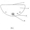
- the locking device 4 both the one-part and the two-part, has adjacent Edges 6 and free edges 7.
- the adjacent edges 6 are with the Connected inner surface. You can use seals 8, z. B. Rubber seals. Another possibility is a locking part 5 to weld.
- the adjacent edge 6 and the free edge 7 determine the surface 9 of the Locking device 4, the surface 9 partially fills the inside diameter of the jacket 1 off.
- the pump mounted in the head 3 draws the fuel through into the interior the check valve 15 mounted in the lower part of the blocking part 5.
- the distance between the two locking parts 5 is less than the distance between a blocking part 5 and the jacket edge 10.
- the specified distance is effective at higher altitudes.
- the tank can have additional openings with heads 11 for additional connections, e.g. B. a safety valve.
- the head 3 as a ring with openings above the lateral surface 1 is formed - the openings have connecting pipes 12.
- the head 3 has, as in the embodiment, a mounting part 13 in the form of an inner ring, with a Row of mounting holes 14.
- the head is in the jacket opening with a Weld seam attached.
Landscapes
- Engineering & Computer Science (AREA)
- Mechanical Engineering (AREA)
- General Engineering & Computer Science (AREA)
- Filling Or Discharging Of Gas Storage Vessels (AREA)
Abstract
Die Erfindung betrifft einen zylindrischen Tank, insbesondere für Flüssiggas. Er ist dadurch gekennzeichnet, dass er im Innenraum des Mantels (1) eine Sperrvorrichtung (4) enthält und in der Mantelöffnung ein Kopf (3) eingesetzt ist. Die Sperrvorrichtung (4) weist eine Fläche (9) auf, die zum Teil den Innenraum des Mantels (1) füllt. <IMAGE>
Description
Aus der Beschreibung des polnischen Gebrauchsmusters 54487 ist ein
Druckbehälter bekannt, der aus einem zylindrischen, beiderseitig mit Bodenplatten
abgeschlossenen Mantel besteht. Der Mantel des Behälters enthält eine Öffnung, in
die ein Armaturenkopf eingesetzt ist.
Der bekannte Behälter kann gebraucht werden, wenn die Mantellänge nicht zu groß
ist. Bei langen Behältern kann die Nutzung dazu führen, dass unter bestimmten
Bedingungen Gas angesaugt wird und nicht das Flüssiggas.
Um diesen Fehler zu beseitigen, beruht die Konstruktion nach der Erfindung darauf,
dass ein zylindrischer Tank, insbesondere für Flüssiggas, der aus einem Mantel mit
Öffnung und Bodenplatten gebildet ist, im Innenraum eine innere Sperrvorrichtung
aufweist. In der Mantelöffnung ist ein Kopf eingesetzt, der sich in der Nähe der
inneren Sperrvorrichtung befindet. Die Fläche der Sperre füllt zum Teil den lichten
Durchmesser des Mantelinnenraums.
Es ist günstig, wenn die innere Sperre zweiteilig ausgebildet ist, und die anliegenden
Kanten der beiden Teile der Sperrvorrichtung mit der Mantelinnenfläche verbunden
sind. Die beiden Teile der Sperrvorrichtung weisen auch eine freie Kante auf. Die
Sperrvorrichtung hat einen Rückschlagventil.
Die anliegenden Sperrkanten können Dichtungen besitzen, mit denen sie mit der
Mantelfläche verbunden werden. Die anliegenden Sperrkanten können mit dem
Mantel mit Hilfe einer Schweißnaht verbunden werden.
Die Entfernung zwischen den beiden Sperrteilen ist vorzugsweise kleiner als die
Entfernung zwischen ihnen und den Mantelkanten. Der Mantel kann zusätzliche
Öffnungen mit Köpfen besitzen.
Der Kopf hat vorzugsweise die Form eine Rings und Öffnungen mit
Anschlussrohren.
Es ist günstig, wenn der Kopf ein Montageteil mit einer Reihe von Montageöffnungen
aufweist.
Der Kopf ist in der Mantelöffnung vorzugsweise mit einer Schweißnaht eingesetzt.
Die Tankkonstruktion erlaubt eine fehlerfreie Nutzung von Behältern, deren Länge im
Verhältnis zum Durchmesser relativ groß ist.
Der Gegenstand der Erfindung wird nun anhand eines Ausführungsbeispiels näher
erläutert. Die Figuren zeigen:
- Fig. 1
- den Grundriss eines Tanks,
- Fig.2
- einen Querschnitt A-A der Fig. 1 des Tanks mit einteiliger Sperrvorrichtung,
- Fig.3
- einen Querschnitt A-A der Fig. 1 des Tanks mit zweiteiliger Sperrvorrichtung, und
- Fig. 4
- die Stirnansicht eines Sperrteils mit einem Rückschlagventil.
Ein zylindrischer Tank, insbesondere für Flüssiggas, besteht gemäß der Erfindung
aus einem zylindrischen Mantel 1 und den Bodenplatten 2. Im dem Mantel gibt es
eine Öffnung, in die ein Kopf 3 eingesetzt ist.
Der Tank weist innen eine Sperrvorrichtung 4 auf, die sich aus zwei Teilen 5
zusammensetzen kann.
Es ist notwendig, dass die Öffnung mit dem Kopf 3 sich in der Nähe der
Sperrvorrichtung 4 befindet. Dies ist dadurch begründet, dass der in dem Kopf 3
montierte Pumpenteil nicht zu lang ausfällt. Er sollte ungefähr bis an den Tankboden
in der Nähe der Sperrvorrichtung 4 zwischen den beiden Sperrteilen 5 reichen.
Die Sperrvorrichtung 4, sowohl die einteilige als auch die zweiteilige, hat anliegende
Kanten 6 und freie Kanten 7. Die anliegenden Kanten 6 sind mit der
Mantelinnenfläche verbunden. Sie können mittels Dichtungen 8, z. B.
Gummidichtungen, verbunden werden. Eine andere Möglichkeit ist, ein Sperrteil 5
anzuschweißen.
Die anliegende Kante 6 und die freie Kante 7 bestimmen die Fläche 9 der
Sperrvorrichtung 4, die Fläche 9 füllt zum Teil den lichten Durchmesser des Mantels
1 aus.
Die in dem Kopf 3 montierte Pumpe saugt den Brennstoff in den Innenraum durch
das im unteren Teil des Sperrteils 5 montierten Rückschlagventil 15 an.
Da die Fläche 9 nicht den ganzen lichten Durchmesser des Mantelinnenraums
einnimmt, gibt es bei einem bestimmten Tankinhalt die Möglichkeit der freien
Brennstoffströmung.
Es ist günstig, wenn die Entfernung zwischen den beiden Sperrteilen 5 kleiner ist als
die Entfernung zwischen einem Sperrteil 5 und dem Mantelrand 10.
Die festgelegte Entfernung ist bei größeren Höhen wirksam.
Der Tank kann zusätzliche Öffnungen mit Köpfen 11 für zusätzliche Anschlüsse, z. B.
eines Sicherheitsventils, haben.
Es ist günstig, wenn der Kopf 3 als Ring mit Öffnungen oberhalb der Mantelfläche 1
ausgebildet ist - die Öffnungen besitzen Anschlussrohre 12. Der Kopf 3 hat, wie in
dem Ausführungsbeispiel, ein Montageteil 13 in Form eines inneren Rings, mit einer
Reihe von Montageöffnungen 14. Der Kopf wird in der Mantelöffnung mit einer
Schweißnaht befestigt.
Claims (11)
- Zylindrischer Tank, insbesondere für Flüssiggas, der einen Mantel mit einer Öffnung und Bodenplatten aufweist, dadurch gekennzeichnet, dass im Innenraum des Tankmantels (1) eine Sperrvorrichtung (4) vorgesehen ist, und in der Mantelöffnung ein Kopf (3) eingesetzt ist, wobei sich der Kopf (3) in der Nähe der inneren Sperrvorrichtung (4) befindet und die innere Sperrvorrichtung (4) eine Fläche (9) aufweist, die zum Teil den lichten Durchmesser des Mantelinnenraums füllt.
- Tank gemäß Anspruch 1, dadurch gekennzeichnet, dass die innere Sperrvorrichtung (4) zweiteilig ausgebildet ist, und dass die beiden Sperrteile (5) anliegende, mit der Innenfläche des Mantels (1) verbundene Kanten (6) und eine freie Kante (7) aufweisen.
- Tank gemäß Anspruch 1, dadurch gekennzeichnet, dass die Sperrvorrichtung (4) ein Rückschlagventil (15) enthält.
- Tank gemäß Anspruch 1 oder 2, dadurch gekennzeichnet, dass die anliegenden Kanten (6) Dichtungen zum Verbinden mit der Fläche des Mantels (1) haben.
- Tank gemäß Anspruch 1 oder 2, dadurch gekennzeichnet, dass die anliegenden Kanten (6) mit der Mantelfläche mit einer Schweißnaht verbunden sind.
- Tank gemäß Anspruch 2, dadurch gekennzeichnet, dass die Entfernung zwischen den Sperrteilen (5) der Sperrvorrichtung (4) kleiner ist, als die Entfernung zwischen den Sperrteilen (5) und den Mantelrändern (10).
- Tank gemäß Anspruch 1, dadurch gekennzeichnet, dass der Mantel (1) zusätzliche Öffnungen mit Köpfen (11 ) aufweist.
- Tank gemäß Anspruch 1, dadurch gekennzeichnet, dass der Kopf (3) ein Ring ist.
- Tank gemäß Anspruch 1 oder 6, dadurch gekennzeichnet, dass der Kopf (3) Öffnungen mit Anschlussrohren (12) aufweist.
- Tank gemäß Anspruch 1 oder 6, dadurch gekennzeichnet, dass der Kopf (3) ein Montageteil (13) mit einer Reihe von Montageöffnungen (14) enthält.
- Tank gemäß Anspruch 1, dadurch gekennzeichnet, dass der Kopf (3) in der Mantelöffnung mit einer Schweißnaht befestigt ist.
Applications Claiming Priority (2)
| Application Number | Priority Date | Filing Date | Title |
|---|---|---|---|
| PL02357749A PL357749A1 (en) | 2002-12-13 | 2002-12-13 | Cylindrical tank, particularly for storing liquefied gas |
| PL35774902 | 2002-12-13 |
Publications (1)
| Publication Number | Publication Date |
|---|---|
| EP1429070A2 true EP1429070A2 (de) | 2004-06-16 |
Family
ID=32322596
Family Applications (1)
| Application Number | Title | Priority Date | Filing Date |
|---|---|---|---|
| EP20030027980 Withdrawn EP1429070A2 (de) | 2002-12-13 | 2003-12-05 | Zylindrischer Tank, insbesondere für Flüssiggas |
Country Status (2)
| Country | Link |
|---|---|
| EP (1) | EP1429070A2 (de) |
| PL (1) | PL357749A1 (de) |
-
2002
- 2002-12-13 PL PL02357749A patent/PL357749A1/xx not_active IP Right Cessation
-
2003
- 2003-12-05 EP EP20030027980 patent/EP1429070A2/de not_active Withdrawn
Also Published As
| Publication number | Publication date |
|---|---|
| PL357749A1 (en) | 2004-06-14 |
Similar Documents
| Publication | Publication Date | Title |
|---|---|---|
| DE2810059A1 (de) | Mehrfachanordnung von motor-kompressoreinheiten fuer kuehlsysteme | |
| DE3009880A1 (de) | Druckbehaelter | |
| DE102005018560B4 (de) | Rohrverbindung | |
| EP1279588B1 (de) | Motorradrahmen | |
| DE3031167A1 (de) | Druckstossdaempfer fuer mit schwachen stroemen arbeitende druckfluessigkeitssysteme | |
| EP1429070A2 (de) | Zylindrischer Tank, insbesondere für Flüssiggas | |
| CH706212B1 (de) | Ausgleichsbehälter für ein Kühlsystem einer Verbrennungskraftmaschine. | |
| EP1614951B1 (de) | Wandarmatur zur Bildung eines fluidführenden Anschlusses | |
| DE3206386A1 (de) | Behaelter mit einem fuellstandsfuehler | |
| DE60111806T2 (de) | Metallaminatdichtung mit Flammringen und eingreifenden Elementen | |
| DE8201025U1 (de) | Automatische Entlüftungseinrichtung | |
| DE899456C (de) | Verschluss fuer den Fuell- und Ausgiesstutzen von tragbaren Behaeltern, insbesondere Kanistern | |
| DE19625061C2 (de) | Kraftstofftank mit Fördereinheit | |
| DE3821331A1 (de) | Lueftungseinrichtung fuer einen vorzugsweise aus kunststoff gefertigten oeltank | |
| DE640600C (de) | Als Heizkoerper dienendes Ausdehnungsgefaess fuer Warmwasser-Sammelheizungsanlagen | |
| EP1429069A2 (de) | Tankeinrichtung, insbesondere für Flüssiggas | |
| DE29707439U1 (de) | Einhakeinrichtung | |
| DE29812726U1 (de) | Behälter mit Trittleiter | |
| EP3050822B1 (de) | Behälter, tankcontaineranordnung | |
| DE6926329U (de) | Verschluss fuer ein nachtraeglich in einen allseitig geschlossenen behaelter geschnittenes mannloch. | |
| DE29612776U1 (de) | Vorrichtung zum Schließen einer Entlastungsöffnung eines Gehäuses eines Druckmeßgerätes sowie zum Belüften des Gehäuses | |
| CH625025A5 (en) | Sealing for cruciform joints of a pressure vessel | |
| DE1476376C (de) | Querstromkühler für Fahrzeugmotoren | |
| DE1987678U (de) | Stehender doppelmanteltank. | |
| DE316289C (de) |
Legal Events
| Date | Code | Title | Description |
|---|---|---|---|
| PUAI | Public reference made under article 153(3) epc to a published international application that has entered the european phase |
Free format text: ORIGINAL CODE: 0009012 |
|
| AK | Designated contracting states |
Kind code of ref document: A2 Designated state(s): AT BE BG CH CY CZ DE DK EE ES FI FR GB GR HU IE IT LI LU MC NL PT RO SE SI SK TR |
|
| AX | Request for extension of the european patent |
Extension state: AL LT LV MK |
|
| STAA | Information on the status of an ep patent application or granted ep patent |
Free format text: STATUS: THE APPLICATION IS DEEMED TO BE WITHDRAWN |
|
| 18D | Application deemed to be withdrawn |
Effective date: 20060701 |