EP1429103A1 - Vorrichtung für die elektrische Verbindung zwischen einer Waffe und einer Munition - Google Patents
Vorrichtung für die elektrische Verbindung zwischen einer Waffe und einer Munition Download PDFInfo
- Publication number
- EP1429103A1 EP1429103A1 EP03293021A EP03293021A EP1429103A1 EP 1429103 A1 EP1429103 A1 EP 1429103A1 EP 03293021 A EP03293021 A EP 03293021A EP 03293021 A EP03293021 A EP 03293021A EP 1429103 A1 EP1429103 A1 EP 1429103A1
- Authority
- EP
- European Patent Office
- Prior art keywords
- rod
- contact
- weapon
- cylinder head
- corner
- Prior art date
- Legal status (The legal status is an assumption and is not a legal conclusion. Google has not performed a legal analysis and makes no representation as to the accuracy of the status listed.)
- Withdrawn
Links
- 229910001080 W alloy Inorganic materials 0.000 claims description 3
- RYGMFSIKBFXOCR-UHFFFAOYSA-N Copper Chemical compound [Cu] RYGMFSIKBFXOCR-UHFFFAOYSA-N 0.000 description 2
- 229910052802 copper Inorganic materials 0.000 description 2
- 239000010949 copper Substances 0.000 description 2
- 239000012212 insulator Substances 0.000 description 2
- WFKWXMTUELFFGS-UHFFFAOYSA-N tungsten Chemical compound [W] WFKWXMTUELFFGS-UHFFFAOYSA-N 0.000 description 2
- 229910052721 tungsten Inorganic materials 0.000 description 2
- 239000010937 tungsten Substances 0.000 description 2
- 229910045601 alloy Inorganic materials 0.000 description 1
- 239000000956 alloy Substances 0.000 description 1
- 230000006835 compression Effects 0.000 description 1
- 238000007906 compression Methods 0.000 description 1
- 238000006073 displacement reaction Methods 0.000 description 1
- 230000000694 effects Effects 0.000 description 1
- 238000010292 electrical insulation Methods 0.000 description 1
- 230000000977 initiatory effect Effects 0.000 description 1
- 238000009434 installation Methods 0.000 description 1
- 239000011810 insulating material Substances 0.000 description 1
- 229910052751 metal Inorganic materials 0.000 description 1
- 239000002184 metal Substances 0.000 description 1
- 239000004575 stone Substances 0.000 description 1
- 238000003466 welding Methods 0.000 description 1
Images




Classifications
-
- F—MECHANICAL ENGINEERING; LIGHTING; HEATING; WEAPONS; BLASTING
- F41—WEAPONS
- F41A—FUNCTIONAL FEATURES OR DETAILS COMMON TO BOTH SMALLARMS AND ORDNANCE, e.g. CANNONS; MOUNTINGS FOR SMALLARMS OR ORDNANCE
- F41A19/00—Firing or trigger mechanisms; Cocking mechanisms
- F41A19/58—Electric firing mechanisms
- F41A19/69—Electric contacts or switches peculiar thereto
- F41A19/70—Electric firing pins; Mountings therefor
Definitions
- the technical field of the invention is that of devices for ensuring an electrical connection between a current generator secured to a weapon and a first contact area secured to ammunition.
- This device includes a axial contact movable relative to the cylinder head corner and which penetrates a deformable contact area integral with the ammunition. This axial contact is moved by a jack hydraulic which avoids any contact bounce.
- This device makes it possible to convey electrical energy important (in the form of pulses of the order of a few hundreds of kilograms Joules and up to the megajoule). Such energy level is implemented today in weapon systems using plasma igniters.
- the hydraulic cylinder is bulky and consumes Energy.
- the device proposed by this patent does not not describe the means ensuring the return of the current from the ammunition to the generator.
- the quality of the return contact must be of a level at least equivalent to that of the contact go.
- the device according to the invention makes it possible to ensure reliably and with a small footprint reduces the connection between the weapon and the ammunition.
- the device according to the invention uses little energy while nevertheless ensuring reliable and rebound-free contact.
- the device according to the invention thus authorizes the passage significant energies (of the order of several hundred kilo Joules).
- the subject of the invention is a device ensuring a electrical connection between an integral current generator of a weapon and a first contact zone integral with a ammunition, device comprising a carried conductive rod by a breech of the weapon and movable in translation by compared to this one to come into contact with the first ammunition contact area, the rod having a point ensuring the deformation of said zone, device characterized in that the rod carries a rack on which meshes with a pinion secured to the cylinder head, said pinion being rotated by a drive means activated when the cylinder head is closed.
- the device when the device according to the invention is applied to a weapon whose cylinder head comprises a wedge, movable in translation along a direction substantially perpendicular to an axis of the tube the weapon, corner driven in its movement by a motor lever pivoting, the device is then characterized in that the drive means comprises a cam secured to an axis bearing the pinion, cam which cooperates with a finger carried by the engine lever ensuring the drive.
- the cam may include a notch inside which will accommodate the finger carried by the engine lever, the finger ensuring locking of the cam in its position pivoted corresponding to the establishment of contact.
- the rod can be pushed into its rest position, corresponding to the opening of the contact, by a spring of reminder.
- the rod may be surrounded by an insulating sheath having a length such that its front end defines a chamber in which the tip of the rod will be housed.
- the cylinder head may have a frontal surface on which will be fixed a conductive crown intended for cooperate with a second annular contact area and secured to ammunition.
- the conductive ring will advantageously be made of a tungsten alloy.
- a weapon 1 has a recoiling mass 2 sliding mounted relative to a cradle 3.
- the receding mass 2 comprises a tube 6 which is equipped with its rear part of a cylinder head sleeve 4, inside from which a closing corner 5 moves (here in position opened).
- a closing corner 5 moves (here in position opened).
- An electric generator 7 is integral with the cradle 3 and it is connected to the cylinder head corner 5 via a connector 8 comprising a male socket 8a integral with the cradle and a female socket 8b secured to the corner.
- the male plug 8a secured to the cradle is fixed to a motor means 9 which here is constituted by a hydraulic cylinder whose body is integral with the cradle 3 of the weapon and whose rod carries the male plug 8a.
- the female socket 8b being integral with the receding mass 2, the recoil of the latter when fired causes a relative displacement of the socket by compared to the male plug, therefore the disconnection.
- Figures 2a and 2b show more precisely the structure of the cylinder head wedge 5.
- the wedge of cylinder head 5 has a substantially parallelepiped shape which is delimited at one of its ends by a semi-cylindrical surface 10. The latter is positioned in look of a gun room ledge when the corner 5 is open to allow the installation of a ammunition in the room.
- the corner 5 carries on its side faces 15a, 15b of the guide surfaces 11 which cooperate with surfaces worn by the cylinder head sleeve 4.
- the female connector 8b is fixed on one side lower 12 of the corner.
- the connector 8b includes an arm 13 carrying the holes 14a, 14b intended to receive the plugs of the male connector.
- the orifices 14a and 14b contain conductive sockets (not shown) which will cooperate with the plugs of the male connector to ensure contact electric.
- the arm 13 is integral with a support 16 forming square and fixed at the corner 5.
- the corner 5 carries on its face intended to come close the weapon chamber a conductive crown 16 which is mounted set in an annular groove carried by the corner 5 and which is intended to cooperate with a shaped contact area annular 27 which is integral with the base 24 of an ammunition (see figure 4).
- a conductive crown 16 which is mounted set in an annular groove carried by the corner 5 and which is intended to cooperate with a shaped contact area annular 27 which is integral with the base 24 of an ammunition (see figure 4).
- We can also refer to the patent FR2824898 which describes in detail a munition base bearing an annular contact on its rear face and which is intended for thus cooperate with the crown 16 of the corner 5.
- the conductive ring 16 will be produced made of a tungsten alloy. This will ensure the holding mechanics of this crown to many shots.
- the contact annular 27 carried by the base 24 will also be produced in a metal or alloy more malleable than tungsten and very conductive for example in copper.
- the crown 16 is electrically connected to one of the connector 8b sockets by a cable 17, connected to a conductive rod 18 integral with the corner 5.
- corner 5 also carries a axial contactor 19 which is located at the axis of the crown 16.
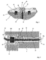
- This contactor is more particularly visible in Figures 3, 4 and 6. It comprises a conductive rod 20 surrounded by an insulating sheath 21.
- Rod 20 and sheath 21 are movable in translation in a bore 22 made in the cylinder head corner 5.
- the rod 20 has a point 20a which is intended to ensure the deformation of an axial contact zone 23 carried by the base 24 of a munition (see FIG. 4).
- the scabbard insulator 21 has a length such that its front end delimits a chamber 25 in which the point 20a is housed of the stem.
- the sleeve 21 is thus housed in a cavity cylindrical 26 carried by an insulating tube 44 integral with the base and which surrounds the axial contact zone 23. On thus improves the electrical insulation between the rod 20 and the crown 16 during the initiation of the ammunition.
- the rod 20 has an enlarged rear portion 20b on which is fixed by welding an electric cable 28 which is connected to a socket of connector 8b.
- the rear part 20b of the rod is also surrounded by the sheath insulator 21 and it is fixed to a cylinder 29 produced in a insulating material which is slidably mounted in a bore 30 enlarged, coaxial with the bore 22 receiving the rod.
- a compression spring 38 is disposed in a bore 43 which connects bore 30 and bore 22. This spring is located interposed between cylinder 29 and a counterbore connecting bore 43 to bore 22. This return spring 38 allows to return the rod 20 to its rest position, away from the ammunition base.
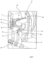
- the cylinder 29 carries a rack 31 (fixed by example by screws) on which a pinion 32 meshes (see Figures 6 and 5) which is integral with an axis 33 substantially perpendicular to bore 30.
- the other end of the axis 33 carries a cam 34 which is disposed at the level of the lateral face 15a of the corner 5.
- the side face 15a of the corner also carries, of a known manner (and already described by patent FR2624961), a profile 35 (see Figure 2a, 5, 7b) on which a roller rolls 36 secured to a pivoting motor lever 37 (see FIG. 5).
- the engine lever 37 is rotated by a shaft fluted 39 which is itself driven by a motor hydraulic (not shown).
- a motor hydraulic not shown
- the lever 37 is pivoted counterclockwise.
- the stone rolls on profile 35 carried by the corner and the lever pushes thus the corner 5 upwards so as to close the cylinder head.
- figure 7a shows the corner in position open
- Figure 7b shows the corner being closing.
- the motor lever 37 carries its end a finger 40 which is intended to cooperate with a notch 41 carried by the cam 34.
- Lever 37 remains in this position until the corner opening. Finger 41 therefore ensures locking of the cam 34 in its pivoted position and thus allows the maintaining the contact rod 20 in engagement in the area contact 23 of the base without risk of rebound. This ensures reliable and excellent electrical contact allowing the passage of a high energy current (several hundred kilo Joules).
Landscapes
- Engineering & Computer Science (AREA)
- General Engineering & Computer Science (AREA)
- Circuit Breakers (AREA)
- Transmission Devices (AREA)
Applications Claiming Priority (2)
| Application Number | Priority Date | Filing Date | Title |
|---|---|---|---|
| FR0215958 | 2002-12-13 | ||
| FR0215958A FR2848654B1 (fr) | 2002-12-13 | 2002-12-13 | Dispositif assurant une liaison electrique entre une arme et une munition |
Publications (1)
| Publication Number | Publication Date |
|---|---|
| EP1429103A1 true EP1429103A1 (de) | 2004-06-16 |
Family
ID=32320241
Family Applications (1)
| Application Number | Title | Priority Date | Filing Date |
|---|---|---|---|
| EP03293021A Withdrawn EP1429103A1 (de) | 2002-12-13 | 2003-12-03 | Vorrichtung für die elektrische Verbindung zwischen einer Waffe und einer Munition |
Country Status (3)
| Country | Link |
|---|---|
| US (1) | US7007586B2 (de) |
| EP (1) | EP1429103A1 (de) |
| FR (1) | FR2848654B1 (de) |
Families Citing this family (10)
| Publication number | Priority date | Publication date | Assignee | Title |
|---|---|---|---|---|
| US7357082B1 (en) * | 2005-09-27 | 2008-04-15 | Jeffrey Racho | Modified shotgun and modified shotgun shell ammunition |
| FR2893381B1 (fr) | 2005-11-14 | 2008-02-01 | Cta Internat Sa | Dispositif de securite de contact |
| US9921028B2 (en) | 2010-01-15 | 2018-03-20 | Colt Canada Ip Holding Partnership | Apparatus and method for powering and networking a rail of a firearm |
| US10477619B2 (en) | 2010-01-15 | 2019-11-12 | Colt Canada Ip Holding Partnership | Networked battle system or firearm |
| US9823043B2 (en) | 2010-01-15 | 2017-11-21 | Colt Canada Ip Holding Partnership | Rail for inductively powering firearm accessories |
| US10337834B2 (en) | 2010-01-15 | 2019-07-02 | Colt Canada Ip Holding Partnership | Networked battle system or firearm |
| US10477618B2 (en) | 2010-01-15 | 2019-11-12 | Colt Canada Ip Holding Partnership | Networked battle system or firearm |
| US10470010B2 (en) | 2010-01-15 | 2019-11-05 | Colt Canada Ip Holding Partnership | Networked battle system or firearm |
| AU2012218790B2 (en) | 2011-02-15 | 2016-11-03 | Colt Canada Ip Holding Partnership | Apparatus and method for inductively powering and networking a rail of a firearm |
| CA2881982C (en) | 2012-08-16 | 2020-10-13 | Colt Canada Corporation | Apparatus and method for powering and networking a rail of a firearm |
Citations (3)
| Publication number | Priority date | Publication date | Assignee | Title |
|---|---|---|---|---|
| US4329908A (en) * | 1980-06-26 | 1982-05-18 | Remington Arms Company, Inc. | Recoil-operated firing pin retractor for electrically-fired guns |
| US4744283A (en) * | 1986-03-17 | 1988-05-17 | Esperanza Y Cia, S.A. | Mortar |
| US5220126A (en) * | 1991-08-23 | 1993-06-15 | Fmc Corporation | High energy intermittent power connector |
Family Cites Families (7)
| Publication number | Priority date | Publication date | Assignee | Title |
|---|---|---|---|---|
| DE2406933A1 (de) * | 1974-02-14 | 1975-08-28 | Heckler & Koch Gmbh | Abzugseinrichtung fuer elektrisch gezuendete waffen |
| US4298914A (en) * | 1978-06-23 | 1981-11-03 | Long Alvin L | Electric firing device |
| DE3608260C2 (de) * | 1986-03-12 | 1996-05-09 | Heckler & Koch Gmbh | Drehbarer Schlagbolzen bei einer Feuerwaffe |
| US5062323A (en) * | 1989-07-31 | 1991-11-05 | Baseline Products, Inc. | Tire repair plug and installation tool |
| US5303495A (en) * | 1992-12-09 | 1994-04-19 | Harthcock Jerry D | Personal weapon system |
| US5901488A (en) * | 1997-12-31 | 1999-05-11 | Aai Corporation | Piezoid electrical gun trigger |
| US6397508B1 (en) * | 2000-08-21 | 2002-06-04 | Smith & Wesson Corp. | Electric firing probe for detonating electrically-fired ammunition in a firearm |
-
2002
- 2002-12-13 FR FR0215958A patent/FR2848654B1/fr not_active Expired - Fee Related
-
2003
- 2003-12-03 EP EP03293021A patent/EP1429103A1/de not_active Withdrawn
- 2003-12-11 US US10/732,313 patent/US7007586B2/en not_active Expired - Fee Related
Patent Citations (3)
| Publication number | Priority date | Publication date | Assignee | Title |
|---|---|---|---|---|
| US4329908A (en) * | 1980-06-26 | 1982-05-18 | Remington Arms Company, Inc. | Recoil-operated firing pin retractor for electrically-fired guns |
| US4744283A (en) * | 1986-03-17 | 1988-05-17 | Esperanza Y Cia, S.A. | Mortar |
| US5220126A (en) * | 1991-08-23 | 1993-06-15 | Fmc Corporation | High energy intermittent power connector |
Also Published As
| Publication number | Publication date |
|---|---|
| US20050115397A1 (en) | 2005-06-02 |
| US7007586B2 (en) | 2006-03-07 |
| FR2848654B1 (fr) | 2005-01-28 |
| FR2848654A1 (fr) | 2004-06-18 |
Similar Documents
| Publication | Publication Date | Title |
|---|---|---|
| EP2260545B1 (de) | Buchsenelement und steckverbinder damit | |
| EP1858124A1 (de) | Koaxialanschluss | |
| FR2992770A1 (fr) | Interrupteur electrique formant coupe-circuit a actionnement rapide | |
| FR2848654A1 (fr) | Dispositif assurant une liaison electrique entre une arme et une munition | |
| EP2285534B1 (de) | Werzeug zum anbringen von drahtgewindeeinsätzen mit verriegelungskeil und kit mit diesem werkzeug | |
| EP0552081B1 (de) | Abstützungsanordnung für Ritzeleinrückvorrichtung für Anlasser eines Verbrennungsmotors | |
| EP1039587A1 (de) | Steckerteil bestimmt für Montage auf einem elektrischen Kabel mit einem schraubenförmig gewellten Aussenleiter und Verfahren zur Montage | |
| EP0500466A2 (de) | Verschluss für die Kontaktaufnahme eines elektrischen oder optischen Steckverbinders | |
| EP1426724A1 (de) | Vorrichtung für die elektrische Verbindung zwischen einer rücklaufenden Masse eines Geschützes und einer festen Wiege | |
| EP1054419B1 (de) | Hochspannungstrennschalter mit schnellbeweglichem Kontakt | |
| EP0321345B1 (de) | Verschlussstück für Artilleriekanone | |
| EP1568109A1 (de) | Elektrischer kontakt mit elastischer rückstellvorrichtung und elektrischem verbindungsteil mit mindestens einem solchen kontakt | |
| EP1709655B1 (de) | Bistabile betätigungsvorrichtung einer bewegbaren, nicht durchgehenden, welle und damit versehener schalter für batterie | |
| EP0685911B1 (de) | Koaxiales elektrisches Verbinderelement mit Schalt-Funktion und elektrischer Verbinder mit einem derartigen Verbinderelement | |
| EP1518979B1 (de) | Schliesszylinder mit elektromechanischer Steuerung | |
| EP0024997B1 (de) | Automatische Zufuhrvorrichtung für Zündkartuschen einer Artilleriekanone | |
| EP1469499A1 (de) | Bistabile Manövriervorrichtung einer translatorisch bewegten Welle | |
| WO1999060325A1 (fr) | Dispositif de percussion d'une carabine a culasse fixe | |
| FR2953982A1 (fr) | Dispositif d'insertion d'une resistance dans un interrupteur a fort courant | |
| EP1845547A2 (de) | Bistabile Stellvorrichtung einer beweglichen Welle und Batteriestromunterbrecher mit einer solchen Vorrichtung | |
| EP0625451B1 (de) | Lenkradschloss für Kraftfahrzeuge | |
| FR2678113A1 (fr) | Systeme de connecteur electrique. | |
| BE659122A (de) | ||
| FR2822507A1 (fr) | Dispositif de manoeuvre d'un cable de commande a came helicoidale | |
| FR2786823A1 (fr) | Dispositif pneumatique permettant le deplacement en translation d'un outil |
Legal Events
| Date | Code | Title | Description |
|---|---|---|---|
| PUAI | Public reference made under article 153(3) epc to a published international application that has entered the european phase |
Free format text: ORIGINAL CODE: 0009012 |
|
| AK | Designated contracting states |
Kind code of ref document: A1 Designated state(s): AT BE BG CH CY CZ DE DK EE ES FI FR GB GR HU IE IT LI LU MC NL PT RO SE SI SK TR |
|
| AX | Request for extension of the european patent |
Extension state: AL LT LV MK |
|
| AKX | Designation fees paid |
Designated state(s): CH DE GB IT LI |
|
| 17P | Request for examination filed |
Effective date: 20041220 |
|
| RAP1 | Party data changed (applicant data changed or rights of an application transferred) |
Owner name: NEXTER SYSTEMS |
|
| GRAP | Despatch of communication of intention to grant a patent |
Free format text: ORIGINAL CODE: EPIDOSNIGR1 |
|
| GRAS | Grant fee paid |
Free format text: ORIGINAL CODE: EPIDOSNIGR3 |
|
| STAA | Information on the status of an ep patent application or granted ep patent |
Free format text: STATUS: THE APPLICATION IS DEEMED TO BE WITHDRAWN |
|
| 18D | Application deemed to be withdrawn |
Effective date: 20091009 |