EP1429150A2 - Verfahren zur Diagnose eines Fehlers in einer Transformatorwindung - Google Patents
Verfahren zur Diagnose eines Fehlers in einer Transformatorwindung Download PDFInfo
- Publication number
- EP1429150A2 EP1429150A2 EP03104592A EP03104592A EP1429150A2 EP 1429150 A2 EP1429150 A2 EP 1429150A2 EP 03104592 A EP03104592 A EP 03104592A EP 03104592 A EP03104592 A EP 03104592A EP 1429150 A2 EP1429150 A2 EP 1429150A2
- Authority
- EP
- European Patent Office
- Prior art keywords
- fault
- winding
- frequency
- parameter
- khz
- Prior art date
- Legal status (The legal status is an assumption and is not a legal conclusion. Google has not performed a legal analysis and makes no representation as to the accuracy of the status listed.)
- Granted
Links
Images


Classifications
-
- G—PHYSICS
- G01—MEASURING; TESTING
- G01R—MEASURING ELECTRIC VARIABLES; MEASURING MAGNETIC VARIABLES
- G01R31/00—Arrangements for testing electric properties; Arrangements for locating electric faults; Arrangements for electrical testing characterised by what is being tested not provided for elsewhere
- G01R31/28—Testing of electronic circuits, e.g. by signal tracer
- G01R31/282—Testing of electronic circuits specially adapted for particular applications not provided for elsewhere
- G01R31/2829—Testing of circuits in sensor or actuator systems
-
- G—PHYSICS
- G01—MEASURING; TESTING
- G01R—MEASURING ELECTRIC VARIABLES; MEASURING MAGNETIC VARIABLES
- G01R31/00—Arrangements for testing electric properties; Arrangements for locating electric faults; Arrangements for electrical testing characterised by what is being tested not provided for elsewhere
- G01R31/50—Testing of electric apparatus, lines, cables or components for short-circuits, continuity, leakage current or incorrect line connections
- G01R31/62—Testing of transformers
Definitions
- the present invention relates to a method for diagnosing a fault on a transformer winding using an analysis of frequency response or FRA (Frequency Response Analysis in English).
- FRA Frequency Response Analysis in English.
- the present invention is more particularly suited to transformers power.
- Power transformers (such as transformers having primary voltages of several hundred kV and powers issued from a few MVA to several hundred MVA) are extremely expensive devices in the interconnection systems of transmission networks. It is therefore very useful to be able to keep in service these transformers for as long as possible, a breakdown or fault in the transformer that can have significant economic consequences due to the shutdown of the distribution network.
- faults such as short circuits can entail risk of explosion or fire.
- FRA Frequency Response Analysis in English
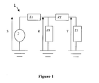
- Figure 1 shows a block diagram of a circuit 1 frequency analysis of an impedance corresponding to the impedance of a transformer winding to be measured.
- the network analyzer 2 generates a measurement signal S.
- the measurement signal S is a sinusoidal signal scanned in frequency.
- the impedances Z1 are for example the impedances of the measurement cables and generally have a value equal to 50 Ohms.
- R is the signal measured between the first end of ZT and the ground.
- T is the signal measured between the second end of ZT and the ground.
- the analyzer 2 then represents, as a function of the frequency, the voltage gain k defined by the following relation:
- the gain k contains the information necessary for studying the impedance ZT and is worth:
- Impedance is measured over a very wide frequency range which can range from a few Hz to ten MHz.
- This reference winding can be either another phase for which we make the assumption that there is no defect, that is the same faultless winding previously measured, i.e. the winding of a identical transformer. We therefore also obtain a gain k 'as a function of the frequency corresponding to this reference winding.
- a first solution then consists in examining by eye the differences between the curves representing k and k 'as a function of frequency.
- this solution presents certain problems.
- a second solution consists in calculating indicators statistics to highlight the differences between the two curves.
- Such statistical indicators are for example the coefficients of correlation calculated in different frequency ranges.
- the present invention aims to provide a method for diagnosing a fault on a transformer winding allowing both increase the number of detectable faults and distinguish the different faults between them.
- the three correlation coefficients are combined with the relative variation of at least a fourth parameter allowing identify certain faults not detected by the values of the coefficients of correlation. According to the value of the relative variation of this fourth parameter, it is also possible to remove an uncertainty between different possible faults.
- said fourth parameter is chosen from the minimum gain, the fundamental resonant frequency or the number of resonant frequencies present beyond a predetermined frequency.
- said minimum gain is determined for a frequency below 10 kHz.
- the minimum gain is defined as the minimum value taken by the voltage gain k as described with reference to FIG. 1 as a function of the measurement frequency; the minimum gain to be determined is the minimum gain for a frequency below 10 kHz.
- the gain may indeed take a minimum value for a higher frequency but this value is less relevant for the identification of faults.
- said three different frequency ranges are respectively [1 kHz-10kHz], [10kHz-100kHz] and [100kHz-1MHz].
- said method comprises a step of determining the relative variation of at least minus a fifth and a sixth parameter, said fifth and sixth parameters being characteristic of said transformer, said variation relative being obtained by comparing said first and second gains.
- said fourth parameter is the minimum gain
- said fifth parameter is the resonant frequency fundamental
- said sixth parameter is the number of frequencies of resonance present beyond a predetermined frequency.
- said method comprises a step of determining a plurality of diagnostic codes, each said codes indicating the belonging of one of said parameters to a predetermined range of values.
- said method comprises a step of determining the presence of a defect and identifying said fault based on said plurality of diagnostic codes.
- said step of determining the presence of a defect and identification of said defect is done by comparison of said plurality of codes with codes stored in a search table.
- FIG. 1 has already been described in relation to the state of the technical.
- the FRA measures presented below will always be made from an analysis circuit as shown in Figure 1.
- Figure 2 shows schematically a transformer three-phase 3.
- Each pair of high and low voltage windings corresponds to a phase of the transformer associated with a core 9 of circuit 4.
- the three transformer phases will be denoted A, B and vs.
- the magnetic circuit 4 and the tank 5 are connected by a link 8 and are grounded.
- FIG. 3 represents the respective gains k and k ' of two high voltage windings of the respective phases C and A of three-phase transformer such as that shown in Figure 2.
- the method according to the invention comprises the calculation of six parameters.
- the first three parameters are the correlation coefficients ⁇ 1 , ⁇ 2 and ⁇ 3 of k and k 'calculated on the three frequency ranges [1 kHz-10kHz], [10kHz-100kHz] and [100kHz-1MHz].
- the fourth parameter is defined as the relative change in the minimum gain CR k at low frequency, ie at a frequency value less than 10 kHz.
- the fifth parameter is defined as the relative change in the fundamental resonant frequency CR f .
- Each measurement of the gain k compared to a measurement of the reference gain k 'therefore corresponds to a sixfold parameter ⁇ 1 , ⁇ 2 , ⁇ 3 , CR k , CR f , CR n ⁇ .
- normal range means that the parameter is within within a so-called normal variation range.
- Table 3 summarizes the normal variations in the case where a different winding is used for the reference (case of Figure 3).
- the method according to the invention comprises a step of comparing these six codes with codes recorded in a search table as presented in table 4.
- Types of faults ⁇ 1 ⁇ 2 ⁇ 3 CR f CR k CR n 1) No fault 0 0 0 0 0 0 2) Bad grounding of the tank (high resistance) 0 0 0-1 0 0 0 3) Absence of earthing of the tank 0 0 0-1 0-9 0-1 0 4) Lack of grounding of the magnetic circuit 0 0 0 0-9 0-1 0 5) Grounded closed loop 0 0 0 0-9 0 0 6) Closed loop set to floating potential 0 0 0-1 0-9 0 0 7) Additional coil in short circuit (same phase) 0-1-2 0 0 3 2-3 0 8) Fault between terminals of the winding (analyzed winding affected) 0-1-2 0-1-2 0-1-2 8 3 0 9) Fault between terminals of the
- the comparison between the calculated parameters and the table research as presented in table 4 can be performed by a computer program developed in a Matlab® environment.
- Faults 2 and 3 correspond to poor grounding of the tank 5; in the case of fault 3, it is a lack of setting earth and in the case of fault 2, earth with resistance high between tank 5 and earth (greater than 50 Ohms).
- Fault 4 corresponds to a lack of circuit earthing magnetic 4, i.e. a break in the connection 8.
- Faults 5 and 6 correspond to current loops of circulation respectively earthed and at floating potential; these loops cause the transformer to overheat.
- Fault 7 corresponds to the presence of an additional turn creating a short circuit on the phase to which the winding belongs analyze.
- Fault 8 corresponds to a fault between the terminals of the winding to be analyzed, i.e. a short circuit of the entire winding.
- Fault 9 corresponds to a fault between the terminals of a winding belonging to the same phase as the winding to be analyzed.
- Fault 10 corresponds to a short circuit present on a turn windings belonging to the same phase as the winding analyze. This fault produces a heating of the transformer.
- Fault 11 corresponds to a short circuit present on several turns belonging to the same phase as the winding to be analyzed. This defect produces a heating of the transformer.
- Fault 12 corresponds to a short circuit fault such as a short circuit between turns, between terminals or on an additional turn. he indicates that the fault is on a phase next to that where the measurement has been carried out and that the phase where the fault is located is the only phase adjacent, i.e. immediately next to the phase where the measurement was performed. So, if the fault is on the central core, the analysis of other phases will produce this code because the central phase is the only phase immediately next to the left and right phases.
- Fault 13 also corresponds to a short circuit fault such as than a short circuit between turns, between terminals or on an additional turn. he indicates however that the fault is not on a single phase being immediately next to the phase where the measurement was made. So if the defect is found on the left nucleus, analysis of the central phase will produce this code because there are two phases immediately next to the central phase and not just one.
- Defect 14 corresponds to an axial displacement of the winding to be analyzed without the latter being too locally damaged, however or buckling of an inner winding.
- Fault 15 corresponds to local mechanical damage on the winding to be analyzed.
- Defect 16 combines faults 14 and 15.
- Fault 17 corresponds to poor electrical continuity in the winding to be analyzed. This poor continuity can be linked to a poor measurement contact.
- Fault 18 corresponds to the earthing of one of the terminals of the winding to be analyzed.
- Fault 19 corresponds to the earthing of one of the terminals of a winding belonging to a phase other than that of the winding analyze.
- Fault 20 corresponds to the earthing of one of the terminals of a winding different from the winding to be analyzed but belonging to the same phase.
- Faults 18, 19 and 20 are more of measurement faults.
- the parameters calculation and research steps in the search table performed by software means can be also performed by operators.
Landscapes
- Physics & Mathematics (AREA)
- Engineering & Computer Science (AREA)
- General Physics & Mathematics (AREA)
- Power Engineering (AREA)
- Electromagnetism (AREA)
- General Engineering & Computer Science (AREA)
- Testing Of Short-Circuits, Discontinuities, Leakage, Or Incorrect Line Connections (AREA)
- Housings And Mounting Of Transformers (AREA)
- Protection Of Transformers (AREA)
Applications Claiming Priority (4)
| Application Number | Priority Date | Filing Date | Title |
|---|---|---|---|
| FR0215590 | 2002-12-10 | ||
| FR0215590A FR2848299A1 (fr) | 2002-12-10 | 2002-12-10 | Procede pour diagnostiquer un defaut sur un enroulement de transformateur |
| FR0301499A FR2848300B3 (fr) | 2002-12-10 | 2003-02-07 | Procede pour diagnostiquer un defaut sur un enroulement de transformateur |
| FR0301499 | 2003-02-07 |
Publications (3)
| Publication Number | Publication Date |
|---|---|
| EP1429150A2 true EP1429150A2 (de) | 2004-06-16 |
| EP1429150A3 EP1429150A3 (de) | 2004-06-23 |
| EP1429150B1 EP1429150B1 (de) | 2007-07-11 |
Family
ID=32327941
Family Applications (1)
| Application Number | Title | Priority Date | Filing Date |
|---|---|---|---|
| EP03104592A Expired - Lifetime EP1429150B1 (de) | 2002-12-10 | 2003-12-08 | Verfahren zur Diagnose eines Fehlers in einer Transformatorwindung |
Country Status (8)
| Country | Link |
|---|---|
| US (1) | US7034547B2 (de) |
| EP (1) | EP1429150B1 (de) |
| CN (1) | CN1291233C (de) |
| AT (1) | ATE366940T1 (de) |
| BR (2) | BR0305838A (de) |
| CA (1) | CA2452400C (de) |
| DE (1) | DE60314830T2 (de) |
| FR (1) | FR2848300B3 (de) |
Families Citing this family (21)
| Publication number | Priority date | Publication date | Assignee | Title |
|---|---|---|---|---|
| FR2860593A1 (fr) * | 2003-10-03 | 2005-04-08 | Alstom T & D Sa | Procede pour diagnostiquer un defaut sur un enroulement de transformateur |
| ES2638765T3 (es) * | 2005-01-21 | 2017-10-24 | Abb Research Ltd | Procedimiento y dispositivo para caracterizar las propiedades lineales de un componente eléctrico |
| EP2024755B1 (de) * | 2006-06-07 | 2010-12-29 | ABB Technology AG | Verfahren zum bestimmen des linearen elektrischen ansprechverhaltens eines transformators, generators oder elektromotors |
| RU2333503C1 (ru) * | 2007-06-18 | 2008-09-10 | Государственное образовательное учреждение высшего профессионального образования Томский политехнический университет | Способ оперативного контроля состояния обмоток однофазного трасформатора с ненагруженной обмоткой |
| CN101738567B (zh) * | 2008-11-25 | 2012-05-30 | 上海市电力公司 | 利用恒流扫频电源激振检测变压器绕组状态的方法 |
| US7961112B2 (en) * | 2009-01-29 | 2011-06-14 | Osisoft, Inc. | Continuous condition monitoring of transformers |
| CN101893673A (zh) * | 2009-05-20 | 2010-11-24 | 遵义长征汽车零部件有限公司 | 利用q值检测点火线圈次级绕组的方法 |
| RU2446406C2 (ru) * | 2009-07-08 | 2012-03-27 | Государственное образовательное учреждение высшего профессионального образования "Вологодский государственный технический университет" (ВоГТУ) | Способ диагностики силовых трехобмоточных трансформаторов |
| JP5193237B2 (ja) * | 2010-01-26 | 2013-05-08 | 株式会社日立製作所 | 電気機器の診断装置、診断方法並びに診断装置積載体 |
| ES2439279T3 (es) * | 2010-12-17 | 2014-01-22 | Abb Research Ltd. | Método y aparato para diagnóstico de transformador |
| RU2457499C1 (ru) * | 2011-05-11 | 2012-07-27 | Денис Владимирович Федоров | Способ диагностирования изоляции токопроводника электрооборудования |
| CN102998545B (zh) * | 2011-09-16 | 2015-04-08 | 国网河南省电力公司电力科学研究院 | 一种变压器绕组工作状态的在线监测方法 |
| CN102809727A (zh) * | 2012-07-13 | 2012-12-05 | 广东电网公司电力科学研究院 | 一种基于频响分析的发电机转子匝间短路故障检测方法 |
| CN103454526B (zh) * | 2013-08-23 | 2016-09-07 | 上海交通大学 | 一种基于klc模型的电力变压器绕组故障类型判定方法 |
| DE102013219657A1 (de) | 2013-09-27 | 2015-04-02 | Continental Teves Ag & Co. Ohg | Verfahren zum Testen eines Transformators |
| CN105180792B (zh) * | 2015-07-01 | 2018-04-17 | 西安交通大学 | 一种基于模型修正的变压器绕组变形定量诊断方法 |
| FR3041763A1 (fr) * | 2015-09-28 | 2017-03-31 | Univ D'artois | Procede de detection d'un defaut dans une machine electrique ac |
| CN107064627B (zh) * | 2016-12-31 | 2018-07-27 | 西南交通大学 | 变压器铁心多点接地故障下绕组频率响应测量系统及方法 |
| CN110161351B (zh) * | 2019-04-29 | 2021-08-24 | 云南电网有限责任公司电力科学研究院 | 一种振荡波下变压器绕组故障试验系统和诊断方法 |
| CN113483831B (zh) * | 2021-09-06 | 2022-01-21 | 沈阳工业大学 | 基于多维变量测量与多维信息诊断的变压器状态辨识方法 |
| CN114444734B (zh) * | 2022-01-27 | 2024-07-19 | 山东电工电气集团有限公司 | 一种基于边缘计算的变压器多模态故障诊断方法 |
Family Cites Families (7)
| Publication number | Priority date | Publication date | Assignee | Title |
|---|---|---|---|---|
| GB8703543D0 (en) * | 1987-02-16 | 1987-03-25 | Era Patents Ltd | Transformer testing |
| US5396172A (en) * | 1993-07-20 | 1995-03-07 | Ontario Hydro | Transformer fault analyzer |
| US5455506A (en) * | 1994-07-21 | 1995-10-03 | Copek Electro Ltee | Method and portable testing apparatus for safely testing an autotransformer for power distribution lines |
| US6549017B2 (en) * | 2000-05-04 | 2003-04-15 | Georgia Tech Research Corporation | System and method for on-line impulse frequency response analysis |
| WO2002035248A1 (en) | 2000-10-27 | 2002-05-02 | Doble Engineering Company | Power transformer transfer function testing |
| US6466034B1 (en) * | 2001-05-29 | 2002-10-15 | Powertech Labs Inc. | Transformer winding movement detection by high frequency internal response analysis |
| US6535000B2 (en) * | 2001-08-02 | 2003-03-18 | Abb Inc. | Method and apparatus for determining the internal impedance of a distribution transformer and sensing DC current through an AC power meter |
-
2003
- 2003-02-07 FR FR0301499A patent/FR2848300B3/fr not_active Expired - Lifetime
- 2003-11-28 US US10/722,527 patent/US7034547B2/en not_active Expired - Lifetime
- 2003-12-05 CA CA2452400A patent/CA2452400C/en not_active Expired - Fee Related
- 2003-12-08 DE DE60314830T patent/DE60314830T2/de not_active Expired - Lifetime
- 2003-12-08 EP EP03104592A patent/EP1429150B1/de not_active Expired - Lifetime
- 2003-12-08 AT AT03104592T patent/ATE366940T1/de not_active IP Right Cessation
- 2003-12-09 BR BR0305838-7A patent/BR0305838A/pt not_active IP Right Cessation
- 2003-12-09 BR BRPI0305838A patent/BRPI0305838B1/pt unknown
- 2003-12-10 CN CNB2003101246335A patent/CN1291233C/zh not_active Expired - Fee Related
Also Published As
| Publication number | Publication date |
|---|---|
| US7034547B2 (en) | 2006-04-25 |
| FR2848300A1 (fr) | 2004-06-11 |
| CN1532554A (zh) | 2004-09-29 |
| EP1429150B1 (de) | 2007-07-11 |
| DE60314830T2 (de) | 2008-03-13 |
| CA2452400A1 (en) | 2004-06-10 |
| BRPI0305838B1 (pt) | 2019-12-31 |
| CA2452400C (en) | 2013-02-19 |
| FR2848300B3 (fr) | 2005-01-07 |
| BR0305838A (pt) | 2004-07-20 |
| US20040164745A1 (en) | 2004-08-26 |
| ATE366940T1 (de) | 2007-08-15 |
| CN1291233C (zh) | 2006-12-20 |
| EP1429150A3 (de) | 2004-06-23 |
| DE60314830D1 (de) | 2007-08-23 |
Similar Documents
| Publication | Publication Date | Title |
|---|---|---|
| EP1429150B1 (de) | Verfahren zur Diagnose eines Fehlers in einer Transformatorwindung | |
| EP2169799B1 (de) | Bestimmung der Richtung eines Erdschluss-Fehlers | |
| EP1522863A1 (de) | Verfahren zur Diagnose eines Fehlers in einer Transformatorenwicklung | |
| EP1815260B1 (de) | Verfahren und einrichtung zur erkennung des elektrischen bogenphänomens auf mindestens einem elektrischen kabel | |
| WO2018020019A1 (fr) | Procédé et système de localisation de défauts sur un câble électrique | |
| FR3104729A1 (fr) | Dispositifs de détection d’un défaut d’arc électrique, appareils de protection électrique associés | |
| US12416658B2 (en) | State analysis of an electrical operating resource | |
| Steenis et al. | Partial discharge diagnostics of long and branched medium-voltage cables | |
| EP3798649A1 (de) | Verfahren zur bestimmung der position einer teilentladungsstelle in einem in betrieb befindlichen hochspannungskabel | |
| EP0537066B1 (de) | Verfahren zur selektiven Detektion von Widerstandsdefekten in Stromverteilungsnetzwerken | |
| KR101363081B1 (ko) | 주파수 도메인 반사계측기를 사용한 네트워크 기기 검출 | |
| CN115079042A (zh) | 一种基于声波的变压器匝间短路检测定位方法及装置 | |
| US20050212524A1 (en) | Electric power line on-line diagnostic method | |
| FR2848299A1 (fr) | Procede pour diagnostiquer un defaut sur un enroulement de transformateur | |
| Bergius | Implementation of on-line partial discharge measurements in medium voltage cable network | |
| JP3629424B2 (ja) | Cvケーブルの絶縁診断方法 | |
| CN117783794B (zh) | 一种变压器内部故障放电量检测方法及设备 | |
| EP4411395B1 (de) | Verfahren zur erkennung eines starken zustandsübergangs in einer leiterleitung, insbesondere einer supraleitenden leitung | |
| Seifi et al. | Localization Algorithm Based on Reflection Coefficient Function Measurements for Internal Incipient and Short Circuit Faults in Transformer Windings | |
| Norouzi et al. | Feasibility of FDA method for the detection and classification of faults in extruded HVDC cables | |
| FR2764071A1 (fr) | Procede d'identification de defauts monophases et dispositif pour la mise en oeuvre d'un tel procede | |
| Nazarov et al. | The investigation of frequency response analysis for power transformers winding condition | |
| CN118584239A (zh) | 一种中压配电网中性点接地方式识别方法、系统、设备及介质 | |
| Foo | Online partial discharge detection and signal analysis for high voltage cables | |
| CN119881500A (zh) | 电缆导体瘦身质量的无损判别方法、装置、设备及介质 |
Legal Events
| Date | Code | Title | Description |
|---|---|---|---|
| PUAI | Public reference made under article 153(3) epc to a published international application that has entered the european phase |
Free format text: ORIGINAL CODE: 0009012 |
|
| PUAL | Search report despatched |
Free format text: ORIGINAL CODE: 0009013 |
|
| AK | Designated contracting states |
Kind code of ref document: A2 Designated state(s): AT BE BG CH CY CZ DE DK EE ES FI FR GB GR HU IE IT LI LU MC NL PT RO SE SI SK TR |
|
| AX | Request for extension of the european patent |
Extension state: AL LT LV MK |
|
| AK | Designated contracting states |
Kind code of ref document: A3 Designated state(s): AT BE BG CH CY CZ DE DK EE ES FI FR GB GR HU IE IT LI LU MC NL PT RO SE SI SK TR |
|
| AX | Request for extension of the european patent |
Extension state: AL LT LV MK |
|
| RAP1 | Party data changed (applicant data changed or rights of an application transferred) |
Owner name: AREVA T&D SA |
|
| 17P | Request for examination filed |
Effective date: 20041214 |
|
| AKX | Designation fees paid |
Designated state(s): AT BE BG CH CY CZ DE DK EE ES FI FR GB GR HU IE IT LI LU MC NL PT RO SE SI SK TR |
|
| GRAP | Despatch of communication of intention to grant a patent |
Free format text: ORIGINAL CODE: EPIDOSNIGR1 |
|
| GRAS | Grant fee paid |
Free format text: ORIGINAL CODE: EPIDOSNIGR3 |
|
| GRAA | (expected) grant |
Free format text: ORIGINAL CODE: 0009210 |
|
| AK | Designated contracting states |
Kind code of ref document: B1 Designated state(s): AT BE BG CH CY CZ DE DK EE ES FI FR GB GR HU IE IT LI LU MC NL PT RO SE SI SK TR |
|
| REG | Reference to a national code |
Ref country code: GB Ref legal event code: FG4D Free format text: NOT ENGLISH |
|
| REG | Reference to a national code |
Ref country code: CH Ref legal event code: EP |
|
| RAP2 | Party data changed (patent owner data changed or rights of a patent transferred) |
Owner name: AREVA T&D SA |
|
| REF | Corresponds to: |
Ref document number: 60314830 Country of ref document: DE Date of ref document: 20070823 Kind code of ref document: P |
|
| REG | Reference to a national code |
Ref country code: IE Ref legal event code: FG4D Free format text: LANGUAGE OF EP DOCUMENT: FRENCH |
|
| NLT2 | Nl: modifications (of names), taken from the european patent patent bulletin |
Owner name: AREVA T&D SA Effective date: 20070815 |
|
| GBT | Gb: translation of ep patent filed (gb section 77(6)(a)/1977) |
Effective date: 20071010 |
|
| PG25 | Lapsed in a contracting state [announced via postgrant information from national office to epo] |
Ref country code: ES Free format text: LAPSE BECAUSE OF FAILURE TO SUBMIT A TRANSLATION OF THE DESCRIPTION OR TO PAY THE FEE WITHIN THE PRESCRIBED TIME-LIMIT Effective date: 20071022 Ref country code: FI Free format text: LAPSE BECAUSE OF FAILURE TO SUBMIT A TRANSLATION OF THE DESCRIPTION OR TO PAY THE FEE WITHIN THE PRESCRIBED TIME-LIMIT Effective date: 20070711 Ref country code: NL Free format text: LAPSE BECAUSE OF FAILURE TO SUBMIT A TRANSLATION OF THE DESCRIPTION OR TO PAY THE FEE WITHIN THE PRESCRIBED TIME-LIMIT Effective date: 20070711 Ref country code: BG Free format text: LAPSE BECAUSE OF FAILURE TO SUBMIT A TRANSLATION OF THE DESCRIPTION OR TO PAY THE FEE WITHIN THE PRESCRIBED TIME-LIMIT Effective date: 20071011 Ref country code: PT Free format text: LAPSE BECAUSE OF FAILURE TO SUBMIT A TRANSLATION OF THE DESCRIPTION OR TO PAY THE FEE WITHIN THE PRESCRIBED TIME-LIMIT Effective date: 20071211 |
|
| NLV1 | Nl: lapsed or annulled due to failure to fulfill the requirements of art. 29p and 29m of the patents act | ||
| PG25 | Lapsed in a contracting state [announced via postgrant information from national office to epo] |
Ref country code: AT Free format text: LAPSE BECAUSE OF FAILURE TO SUBMIT A TRANSLATION OF THE DESCRIPTION OR TO PAY THE FEE WITHIN THE PRESCRIBED TIME-LIMIT Effective date: 20070711 |
|
| REG | Reference to a national code |
Ref country code: IE Ref legal event code: FD4D |
|
| PG25 | Lapsed in a contracting state [announced via postgrant information from national office to epo] |
Ref country code: GR Free format text: LAPSE BECAUSE OF FAILURE TO SUBMIT A TRANSLATION OF THE DESCRIPTION OR TO PAY THE FEE WITHIN THE PRESCRIBED TIME-LIMIT Effective date: 20071012 Ref country code: DK Free format text: LAPSE BECAUSE OF FAILURE TO SUBMIT A TRANSLATION OF THE DESCRIPTION OR TO PAY THE FEE WITHIN THE PRESCRIBED TIME-LIMIT Effective date: 20070711 |
|
| PLBE | No opposition filed within time limit |
Free format text: ORIGINAL CODE: 0009261 |
|
| STAA | Information on the status of an ep patent application or granted ep patent |
Free format text: STATUS: NO OPPOSITION FILED WITHIN TIME LIMIT |
|
| PG25 | Lapsed in a contracting state [announced via postgrant information from national office to epo] |
Ref country code: SK Free format text: LAPSE BECAUSE OF FAILURE TO SUBMIT A TRANSLATION OF THE DESCRIPTION OR TO PAY THE FEE WITHIN THE PRESCRIBED TIME-LIMIT Effective date: 20070711 Ref country code: IE Free format text: LAPSE BECAUSE OF FAILURE TO SUBMIT A TRANSLATION OF THE DESCRIPTION OR TO PAY THE FEE WITHIN THE PRESCRIBED TIME-LIMIT Effective date: 20070711 Ref country code: CZ Free format text: LAPSE BECAUSE OF FAILURE TO SUBMIT A TRANSLATION OF THE DESCRIPTION OR TO PAY THE FEE WITHIN THE PRESCRIBED TIME-LIMIT Effective date: 20070711 |
|
| 26N | No opposition filed |
Effective date: 20080414 |
|
| BERE | Be: lapsed |
Owner name: REVA T&D SA Effective date: 20071231 |
|
| PG25 | Lapsed in a contracting state [announced via postgrant information from national office to epo] |
Ref country code: SE Free format text: LAPSE BECAUSE OF FAILURE TO SUBMIT A TRANSLATION OF THE DESCRIPTION OR TO PAY THE FEE WITHIN THE PRESCRIBED TIME-LIMIT Effective date: 20071011 Ref country code: RO Free format text: LAPSE BECAUSE OF FAILURE TO SUBMIT A TRANSLATION OF THE DESCRIPTION OR TO PAY THE FEE WITHIN THE PRESCRIBED TIME-LIMIT Effective date: 20070711 |
|
| PG25 | Lapsed in a contracting state [announced via postgrant information from national office to epo] |
Ref country code: MC Free format text: LAPSE BECAUSE OF NON-PAYMENT OF DUE FEES Effective date: 20071231 |
|
| REG | Reference to a national code |
Ref country code: CH Ref legal event code: PL |
|
| PG25 | Lapsed in a contracting state [announced via postgrant information from national office to epo] |
Ref country code: BE Free format text: LAPSE BECAUSE OF NON-PAYMENT OF DUE FEES Effective date: 20071231 |
|
| PG25 | Lapsed in a contracting state [announced via postgrant information from national office to epo] |
Ref country code: CH Free format text: LAPSE BECAUSE OF NON-PAYMENT OF DUE FEES Effective date: 20071231 Ref country code: LI Free format text: LAPSE BECAUSE OF NON-PAYMENT OF DUE FEES Effective date: 20071231 |
|
| PG25 | Lapsed in a contracting state [announced via postgrant information from national office to epo] |
Ref country code: EE Free format text: LAPSE BECAUSE OF FAILURE TO SUBMIT A TRANSLATION OF THE DESCRIPTION OR TO PAY THE FEE WITHIN THE PRESCRIBED TIME-LIMIT Effective date: 20070711 |
|
| PG25 | Lapsed in a contracting state [announced via postgrant information from national office to epo] |
Ref country code: SI Free format text: LAPSE BECAUSE OF FAILURE TO SUBMIT A TRANSLATION OF THE DESCRIPTION OR TO PAY THE FEE WITHIN THE PRESCRIBED TIME-LIMIT Effective date: 20070711 |
|
| PG25 | Lapsed in a contracting state [announced via postgrant information from national office to epo] |
Ref country code: CY Free format text: LAPSE BECAUSE OF FAILURE TO SUBMIT A TRANSLATION OF THE DESCRIPTION OR TO PAY THE FEE WITHIN THE PRESCRIBED TIME-LIMIT Effective date: 20070711 |
|
| PG25 | Lapsed in a contracting state [announced via postgrant information from national office to epo] |
Ref country code: LU Free format text: LAPSE BECAUSE OF NON-PAYMENT OF DUE FEES Effective date: 20071208 |
|
| PG25 | Lapsed in a contracting state [announced via postgrant information from national office to epo] |
Ref country code: TR Free format text: LAPSE BECAUSE OF FAILURE TO SUBMIT A TRANSLATION OF THE DESCRIPTION OR TO PAY THE FEE WITHIN THE PRESCRIBED TIME-LIMIT Effective date: 20070711 Ref country code: HU Free format text: LAPSE BECAUSE OF FAILURE TO SUBMIT A TRANSLATION OF THE DESCRIPTION OR TO PAY THE FEE WITHIN THE PRESCRIBED TIME-LIMIT Effective date: 20080112 |
|
| PG25 | Lapsed in a contracting state [announced via postgrant information from national office to epo] |
Ref country code: IT Free format text: LAPSE BECAUSE OF NON-PAYMENT OF DUE FEES Effective date: 20071231 |
|
| REG | Reference to a national code |
Ref country code: DE Ref legal event code: R082 Ref document number: 60314830 Country of ref document: DE Representative=s name: ZEITLER VOLPERT KANDLBINDER, DE |
|
| REG | Reference to a national code |
Ref country code: FR Ref legal event code: CD Owner name: ALSTOM GRID SAS, FR Effective date: 20121204 Ref country code: FR Ref legal event code: CA Effective date: 20121204 |
|
| REG | Reference to a national code |
Ref country code: DE Ref legal event code: R082 Ref document number: 60314830 Country of ref document: DE Representative=s name: ZEITLER VOLPERT KANDLBINDER, DE Effective date: 20121211 Ref country code: DE Ref legal event code: R081 Ref document number: 60314830 Country of ref document: DE Owner name: ALSTOM TECHNOLOGY LTD., CH Free format text: FORMER OWNER: AREVA T&D SA, PARIS, FR Effective date: 20121211 Ref country code: DE Ref legal event code: R081 Ref document number: 60314830 Country of ref document: DE Owner name: ALSTOM GRID SAS, FR Free format text: FORMER OWNER: AREVA T&D SA, PARIS, FR Effective date: 20121211 Ref country code: DE Ref legal event code: R082 Ref document number: 60314830 Country of ref document: DE Representative=s name: ZEITLER VOLPERT KANDLBINDER PATENTANWAELTE PAR, DE Effective date: 20121211 Ref country code: DE Ref legal event code: R082 Ref document number: 60314830 Country of ref document: DE Representative=s name: ZEITLER VOLPERT KANDLBINDER PATENT- UND RECHTS, DE Effective date: 20121211 |
|
| REG | Reference to a national code |
Ref country code: DE Ref legal event code: R082 Ref document number: 60314830 Country of ref document: DE Representative=s name: ZEITLER VOLPERT KANDLBINDER, DE |
|
| REG | Reference to a national code |
Ref country code: DE Ref legal event code: R082 Ref document number: 60314830 Country of ref document: DE Representative=s name: ZEITLER VOLPERT KANDLBINDER PATENTANWAELTE PAR, DE Effective date: 20130610 Ref country code: DE Ref legal event code: R082 Ref document number: 60314830 Country of ref document: DE Representative=s name: ZEITLER VOLPERT KANDLBINDER PATENT- UND RECHTS, DE Effective date: 20130610 Ref country code: DE Ref legal event code: R081 Ref document number: 60314830 Country of ref document: DE Owner name: ALSTOM TECHNOLOGY LTD., CH Free format text: FORMER OWNER: ALSTOM GRID SAS, PARIS, FR Effective date: 20130610 Ref country code: DE Ref legal event code: R082 Ref document number: 60314830 Country of ref document: DE Representative=s name: ZEITLER VOLPERT KANDLBINDER, DE Effective date: 20130610 |
|
| REG | Reference to a national code |
Ref country code: FR Ref legal event code: TP Owner name: ALSTOM TECHNOLOGY LTD, CH Effective date: 20130710 |
|
| REG | Reference to a national code |
Ref country code: GB Ref legal event code: 732E Free format text: REGISTERED BETWEEN 20130815 AND 20130821 |
|
| REG | Reference to a national code |
Ref country code: FR Ref legal event code: PLFP Year of fee payment: 13 |
|
| REG | Reference to a national code |
Ref country code: FR Ref legal event code: PLFP Year of fee payment: 14 |
|
| REG | Reference to a national code |
Ref country code: FR Ref legal event code: PLFP Year of fee payment: 15 |
|
| REG | Reference to a national code |
Ref country code: DE Ref legal event code: R079 Ref document number: 60314830 Country of ref document: DE Free format text: PREVIOUS MAIN CLASS: G01R0031060000 Ipc: G01R0031720000 |
|
| PGFP | Annual fee paid to national office [announced via postgrant information from national office to epo] |
Ref country code: DE Payment date: 20191210 Year of fee payment: 17 |
|
| PGFP | Annual fee paid to national office [announced via postgrant information from national office to epo] |
Ref country code: FR Payment date: 20191219 Year of fee payment: 17 |
|
| PGFP | Annual fee paid to national office [announced via postgrant information from national office to epo] |
Ref country code: GB Payment date: 20191220 Year of fee payment: 17 |
|
| REG | Reference to a national code |
Ref country code: DE Ref legal event code: R119 Ref document number: 60314830 Country of ref document: DE |
|
| GBPC | Gb: european patent ceased through non-payment of renewal fee |
Effective date: 20201208 |
|
| PG25 | Lapsed in a contracting state [announced via postgrant information from national office to epo] |
Ref country code: FR Free format text: LAPSE BECAUSE OF NON-PAYMENT OF DUE FEES Effective date: 20201231 |
|
| PG25 | Lapsed in a contracting state [announced via postgrant information from national office to epo] |
Ref country code: GB Free format text: LAPSE BECAUSE OF NON-PAYMENT OF DUE FEES Effective date: 20201208 Ref country code: DE Free format text: LAPSE BECAUSE OF NON-PAYMENT OF DUE FEES Effective date: 20210701 |