EP1429533A2 - Image processing method and image processing system using the same - Google Patents
Image processing method and image processing system using the same Download PDFInfo
- Publication number
- EP1429533A2 EP1429533A2 EP03028704A EP03028704A EP1429533A2 EP 1429533 A2 EP1429533 A2 EP 1429533A2 EP 03028704 A EP03028704 A EP 03028704A EP 03028704 A EP03028704 A EP 03028704A EP 1429533 A2 EP1429533 A2 EP 1429533A2
- Authority
- EP
- European Patent Office
- Prior art keywords
- image
- output device
- image output
- supply device
- image data
- Prior art date
- Legal status (The legal status is an assumption and is not a legal conclusion. Google has not performed a legal analysis and makes no representation as to the accuracy of the status listed.)
- Withdrawn
Links
Images








Classifications
-
- H—ELECTRICITY
- H04—ELECTRIC COMMUNICATION TECHNIQUE
- H04N—PICTORIAL COMMUNICATION, e.g. TELEVISION
- H04N1/00—Scanning, transmission or reproduction of documents or the like, e.g. facsimile transmission; Details thereof
- H04N1/00127—Connection or combination of a still picture apparatus with another apparatus, e.g. for storage, processing or transmission of still picture signals or of information associated with a still picture
- H04N1/00132—Connection or combination of a still picture apparatus with another apparatus, e.g. for storage, processing or transmission of still picture signals or of information associated with a still picture in a digital photofinishing system, i.e. a system where digital photographic images undergo typical photofinishing processing, e.g. printing ordering
- H04N1/00167—Processing or editing
-
- H—ELECTRICITY
- H04—ELECTRIC COMMUNICATION TECHNIQUE
- H04N—PICTORIAL COMMUNICATION, e.g. TELEVISION
- H04N1/00—Scanning, transmission or reproduction of documents or the like, e.g. facsimile transmission; Details thereof
- H04N1/00127—Connection or combination of a still picture apparatus with another apparatus, e.g. for storage, processing or transmission of still picture signals or of information associated with a still picture
- H04N1/00132—Connection or combination of a still picture apparatus with another apparatus, e.g. for storage, processing or transmission of still picture signals or of information associated with a still picture in a digital photofinishing system, i.e. a system where digital photographic images undergo typical photofinishing processing, e.g. printing ordering
- H04N1/00169—Digital image input
- H04N1/00172—Digital image input directly from a still digital camera or from a storage medium mounted in a still digital camera
-
- H—ELECTRICITY
- H04—ELECTRIC COMMUNICATION TECHNIQUE
- H04N—PICTORIAL COMMUNICATION, e.g. TELEVISION
- H04N1/00—Scanning, transmission or reproduction of documents or the like, e.g. facsimile transmission; Details thereof
- H04N1/00127—Connection or combination of a still picture apparatus with another apparatus, e.g. for storage, processing or transmission of still picture signals or of information associated with a still picture
- H04N1/00132—Connection or combination of a still picture apparatus with another apparatus, e.g. for storage, processing or transmission of still picture signals or of information associated with a still picture in a digital photofinishing system, i.e. a system where digital photographic images undergo typical photofinishing processing, e.g. printing ordering
- H04N1/00185—Image output
- H04N1/00188—Printing, e.g. prints or reprints
-
- H—ELECTRICITY
- H04—ELECTRIC COMMUNICATION TECHNIQUE
- H04N—PICTORIAL COMMUNICATION, e.g. TELEVISION
- H04N1/00—Scanning, transmission or reproduction of documents or the like, e.g. facsimile transmission; Details thereof
- H04N1/00127—Connection or combination of a still picture apparatus with another apparatus, e.g. for storage, processing or transmission of still picture signals or of information associated with a still picture
- H04N1/00278—Connection or combination of a still picture apparatus with another apparatus, e.g. for storage, processing or transmission of still picture signals or of information associated with a still picture with a printing apparatus, e.g. a laser beam printer
-
- H—ELECTRICITY
- H04—ELECTRIC COMMUNICATION TECHNIQUE
- H04N—PICTORIAL COMMUNICATION, e.g. TELEVISION
- H04N1/00—Scanning, transmission or reproduction of documents or the like, e.g. facsimile transmission; Details thereof
- H04N1/00127—Connection or combination of a still picture apparatus with another apparatus, e.g. for storage, processing or transmission of still picture signals or of information associated with a still picture
- H04N1/00132—Connection or combination of a still picture apparatus with another apparatus, e.g. for storage, processing or transmission of still picture signals or of information associated with a still picture in a digital photofinishing system, i.e. a system where digital photographic images undergo typical photofinishing processing, e.g. printing ordering
-
- H—ELECTRICITY
- H04—ELECTRIC COMMUNICATION TECHNIQUE
- H04N—PICTORIAL COMMUNICATION, e.g. TELEVISION
- H04N2201/00—Indexing scheme relating to scanning, transmission or reproduction of documents or the like, and to details thereof
- H04N2201/0008—Connection or combination of a still picture apparatus with another apparatus
- H04N2201/0015—Control of image communication with the connected apparatus, e.g. signalling capability
-
- H—ELECTRICITY
- H04—ELECTRIC COMMUNICATION TECHNIQUE
- H04N—PICTORIAL COMMUNICATION, e.g. TELEVISION
- H04N2201/00—Indexing scheme relating to scanning, transmission or reproduction of documents or the like, and to details thereof
- H04N2201/0008—Connection or combination of a still picture apparatus with another apparatus
- H04N2201/0015—Control of image communication with the connected apparatus, e.g. signalling capability
- H04N2201/0022—Selecting or switching between an image communication mode and a non-image communication mode
-
- H—ELECTRICITY
- H04—ELECTRIC COMMUNICATION TECHNIQUE
- H04N—PICTORIAL COMMUNICATION, e.g. TELEVISION
- H04N2201/00—Indexing scheme relating to scanning, transmission or reproduction of documents or the like, and to details thereof
- H04N2201/0008—Connection or combination of a still picture apparatus with another apparatus
- H04N2201/0015—Control of image communication with the connected apparatus, e.g. signalling capability
- H04N2201/0027—Adapting to communicate with plural different types of apparatus
-
- H—ELECTRICITY
- H04—ELECTRIC COMMUNICATION TECHNIQUE
- H04N—PICTORIAL COMMUNICATION, e.g. TELEVISION
- H04N2201/00—Indexing scheme relating to scanning, transmission or reproduction of documents or the like, and to details thereof
- H04N2201/0008—Connection or combination of a still picture apparatus with another apparatus
- H04N2201/0034—Details of the connection, e.g. connector, interface
- H04N2201/0048—Type of connection
- H04N2201/0049—By wire, cable or the like
-
- H—ELECTRICITY
- H04—ELECTRIC COMMUNICATION TECHNIQUE
- H04N—PICTORIAL COMMUNICATION, e.g. TELEVISION
- H04N2201/00—Indexing scheme relating to scanning, transmission or reproduction of documents or the like, and to details thereof
- H04N2201/0008—Connection or combination of a still picture apparatus with another apparatus
- H04N2201/0034—Details of the connection, e.g. connector, interface
- H04N2201/0048—Type of connection
- H04N2201/0055—By radio
Definitions
- the present invention relates to an image processing method and an image processing system, wherein control information and image data files are transmitted over a communication path, and images based on the image data files which are stored in an image supply device, are output by way of an image output device.
- Japanese Patent Publication No. 2002-330394A discloses a so-called direct print system, wherein a digital still camera is connected to a printer without involvement of a personal computer or the like, and images captured by the digital still camera are printed by the printer.
- image data, a print job start command, and the like are exchanged between the digital still camera and the printer through use of a protocol unique to a vendor.
- an image processing method performed by an image output device connected to an image supply device storing image data, via a communication path through which the image data is communicated, the method comprising steps of:
- a protocol can be made easy to correct after prescription in relation to the control information item to be exchanged between the image supply device and the image output device by utilization of extensibility of a syntax of the markup language while compatibility between a plurality of vendors is maintained.
- the image output device is a printer
- the image supply device is a digital camera
- mutual direct printing can be performed between a digital camera offered by any of a plurality of vendors and a printer offered by any of a plurality of vendors, without use of host equipment such as a personal computer.
- the markup language enables additional definition of a document form.
- the markup language is one of a standard generalized markup language (SGML), an extensible markup language (XML), and a language having a hierarchical compatibility with the SGML or the XML.
- SGML standard generalized markup language
- XML extensible markup language
- a language having a hierarchical compatibility with the SGML or the XML is preferable.
- the script includes a control command for the image processing, a response for the control command, and a notification of a status of the image output device, which are described by the markup language.
- control information item does not contain the image data therein.
- control information item described by the markup language can be communicated independently of the image data to be subjected to the image processing, without changing an existing format of the image data.
- the format of image data includes, e.g., JPEG.
- the image processing method further comprises a step of generating a control signal for controlling an image output mechanism, based on the control information item and the image data.
- the image supply device can be manufactured inexpensively without a function for generating from the image data a control signal for controlling the image output device.
- the image processing method further comprises a step of providing a parser, which analyzes a syntax of the markup language to interpret a tag of the markup language which is related to the image processing.
- the parser can be realized by a simple circuit or program, and the image output device can be made inexpensive.
- an image processing method performed by an image output device connected to an image supply device storing image data, via a communication path, the method comprising steps of:
- the script can be prepared by editing one of the templates, the script can be generated quickly.
- an information processing method performed by an image supply device connected to an image output device via a communication path, the method comprising steps of:
- an information processing method performed by an image supply device connected to an image output device via a communication path, the method comprising steps of:
- the parser can be realized by a simple circuit or program, and the image output device can be made inexpensive.
- an image processing method performed by an image supply device connected to an image supply output via a communication path, the method comprising steps of:
- the script can be prepared by editing one of the templates, the script can be generated quickly.
- an image processing method performed by an image supply device connected to an image supply output via a communication path through which the image data is communicated, the method comprising steps of:
- an image processing method performed by an image supply device storing image data and an image output device performing image processing with respect to the image data, which are connected via a communication path through which the image data is communicated, the method comprising steps of:
- the image output device controls a flow of the image processing.
- the image supply device is required to perform only a small amount of information processing. Even when the image supply device has a low level of information processing performance, the image supply device can be made inexpensive.
- the image processing method further comprises a step of transmitting, from the image supply device to the image output device, a job start command as the script, in a case where a predetermined actuation on a control panel of the image supply device is detected.
- the image output device performs the image processing in response to the job start command.
- the image processing method further comprises steps of:
- the image supply device controls a flow of the image processing.
- the image input device is required to perform only a small amount of information processing. Even when the image output device has a low level of information processing performance, the image output device can be made inexpensive.
- the image processing method further comprises a step of transmitting, from the image output device to the image supply device, a job start command as the script, in a case where a predetermined actuation on a control panel of the image output device is detected.
- the image supply device transmits the image data in response to the job start command.
- an image processing method performed by an image supply device storing image data and an image output device performing image processing with respect to the image data, which are connected via a communication path through which the image data is communicated, the method comprising steps of:
- the image supply device specifies one of the image data and the job specification file, by a script including a job start command described by the markup language; the image output device determines which one of the image data and the job specification file is specified by the job start command; the image output device acquires the image data from the image supply device, in a case where the image output device determines that the job start command specifies the image data; and the image output device first acquires the job specification file from the image supply device, in a case where the image output device determines that the job start command specifies the job specification file, and then acquires the image data specified by the job specification file, from the image supply device.
- At least one image data to be subjected to the image processing can be specified on a per-image-data basis or collectively by the job specification file.
- Image output jobs of various patterns can be performed.
- the job specification file includes at least one processing condition information item each associated with one of the at least one image processing job.
- the job specification file is stored by a digital print order format (DPOF) standard.
- DPOF digital print order format
- an image processing method performed by an image supply device storing image data and an image output device performing image processing with respect to the image data, which are connected via a communication path through which the image data is communicated, the method comprising steps of:
- the status information item includes a resumption information item which specifies a printed object which is allocated at a predetermined position in a page layout, and the method further comprises steps of:
- the print operation in the event of occurrence of a failure in the image output device, the print operation can be correctly resumed, after recovery, from a location in the job where the processing has been interrupted.
- the resumption information item is transmitted only in a case where the print operation is halted.
- the resumption information item is transmitted every time a page break is conducted during the print operation.
- the resumption information item includes at least one of a path information item indicating where the one image data is stored in the image supply device and a number information item indicating how many times the printed object is to be supplied to the image output device repetitively.
- image data to be first printed is accurately determined at the time of resumption. Hence, print processing can be accurately resumed after recovery.
- the number information item is corrected so as to indicate a remained number of the repetitive supply of the one image data before the one image data is supplied to the image output device, in a case where a page break is conducted during the supply of the one image data.
- the image processing method further comprises steps of:
- the print operation is resumed in response to a predetermined command after having been recovered thoroughly, and print processing can be accurately resumed after recovery.
- an image processing system comprising:
- an image output device comprising:
- an image supply device comprising:
- a computer program product comprising a computer program which causes a computer to serve as the communication controller in the above image output device.
- a computer program product comprising a computer program which causes a computer to serve as the communication controller in the above image supply device.
- Fig. 1 shows an image output system according to a first embodiment of the invention.
- This image output system can be taken as one type of so-called direct print system.
- an image output device 1 is a device for outputting images on the basis of image data.
- the image output device 1 is embodied in the form of a printer or the like which prints images on paper on the basis of image data.
- An image supply device 2 is a device capable of storing image data and transmitting image data as required.
- the image supply device 2 is embodied in the form of a digital still camera or the like which stores captured images on a predetermined storage medium as image data.
- a communication path 3 is a transmission medium for connecting the image output device 1 to the image supply device 2.
- the communication path 3 is not limited to a cable communication path, and a wireless communication path may also be employed.
- a universal serial bus (USE) cable is used as the communication path 3.
- an unillustrated connector is provided on the image output device 1 and the image supply device 2, thereby connecting connectors provided on respective ends of the cable of the communication path 3 to connectors of the devices 1 and 2.
- a communicator 11 is a circuit for communicating various information items as electrical signals via the communication path 3.
- a communication controller 12 is a circuit or device which controls the communicator 11 to exchange information with a mating device in accordance with various protocols. The communicator 11 and the communication controller 12 exchange, by way of the communication path 3, control information pertaining to an image output as a series of scripts described in markup languages.
- An output controller 13 is a circuit or device which controls and monitors an output mechanism 14, thereby controlling image output processing (i.e., print processing in a case where the image output device 1 is a printer).
- the output controller 13 controls a processing flow pertaining to an image output.
- the output mechanism 14 is a mechanical and/or electrical constitution section for outputting images. In the case of a printer, the output mechanism 14 corresponds to a print mechanism and a paper feed mechanism.
- the output controller 13 and the output mechanism 14 output an image on the basis of image data.
- a control panel 15 is a circuit or device which is to be manipulated by the user and outputs a signal in response to manipulation. Various switches or a touch panel is used as the control panel 15, as required.
- a display 16 is a device for display various information items. Various indicators or a liquid-crystal display is used as the display 16, as required.
- a power supply 17 is a circuit which is connected to commercial power or an AC/DC converter and feeds supplied power to internal circuits.
- a communicator 21 is a circuit which exchanges various information items in the form of electrical signals by way of the communication path 3.
- a communication controller 22 is a circuit or device which controls the communicator 21 to exchange information with a mating device in accordance with various protocols. The communicator 21 and the communication controller 22 exchange, by way of the communication path 3, control information pertaining to an image output as a series of scripts described in markup languages.
- a central controller 23 is a circuit or device which performs various processing operations while exchanging various information items with circuits or devices having various functions, such as the communication controller 22 and a storage medium 24.
- the storage medium 24 is a device which stores at least one image data file 31.
- the image data file 31 is a file which includes image data pertaining to, e.g., images captured by a digital camera, or other images.
- the format of the image data is, e.g., a JPEG (Joint Photographic Experts Group) format or an EXIF (Exchangeable Image File) format.
- Semiconductor memory a memory card using semiconductor memory, a magnetic storage medium, an optical storage medium, or an electro-optical storage medium is used as the storage medium 24.
- the storage medium may be fixed or removably attached to the image supply device 2.
- a control panel 25 is a circuit or device which is to be manipulated by the user and outputs a signal in response to manipulation.
- Various switches or a touch panel is used as the control panel 25, as required.
- a display 26 is a device for display various information items, such as images based on image data.
- Various indicators or a liquid-crystal display is used as the display 26, as required.
- a battery 27 supplies power to intemal circuits of the image supply device 2.
- a storage battery or a disposable battery is used as the battery 27.
- the battery 27 is provided as a power source.
- a power supply as well as the power supply 17 of the image output device 1 may be provided as a power source.
- Fig. 2 shows an example protocol used between the image output device 1 and the image supply device 2.
- the communication path 3 that is, a USB cable
- a USB layer is adopted as a layer for controlling the physical layer.
- a still image capture device class (SIC) is used as a USB class.
- SIC still image capture device class
- USB 1.1 and USB 2.0 are currently in use.
- the next version or subsequent versions, which would be proposed in future, may also be used, or a communication standard equivalent to the USB may also be used instead.
- the image output device 1 serves as a host
- the image supply device 2 serves as a device.
- a picture transfer protocol is used at a higher level for specifying control of a digital still picture device (DSPD) from the outside or transfer of image data to the outside of the digital still picture device (DSPD).
- DSPD digital still picture device
- "PIMA15740:2000” proposed by Photographic and Imaging Manufacturers Association, Inc is available as a set of PTP standards.
- PTP is a protocol which offers a communications system for exchanging image data between DSPDs.
- an object e.g., an image data file
- an object ID i.e., an object handle
- a direct print service (hereinafter abbreviated as "DPS") protocol is used at a higher level of the PTP for supplying image data stored in the image supply device 2, such as a digital camera, directly to the image output device 1, such as a printer, by way of the communication path 3, to thereby perform printing operation.
- DPS direct print service
- control information about an image output is exchanged as a series of scripts described in an markup language (here, XML: Extensible Markup Language) between the image output device 1 and the image supply device 2 by way of the communication path 3.
- Control information pertaining to an image output includes various commands pertaining to image output processing, responses to the commands, and notification of statuses of devices.
- the script includes only control information and does not include any image data which are objects of image output operation. Specifically, the script includes information about a location for storing image data files, but does not include image data.
- a low-level layer of the DPS protocol is not limited to the PTP. Therefore, a wrapper layer is provided between the DPS protocol and a low-level layer (here a PTP) for achieving consistency between the DPS protocol and low-level layers of a plurality of types.
- a wrapper layer is provided between the DPS protocol and a low-level layer (here a PTP) for achieving consistency between the DPS protocol and low-level layers of a plurality of types.
- the physical layer is embodied by the communicator 11, the communication path 3, and the communicator 21.
- the USB layer is embodied by the communicator 11 and the communicator 21.
- the PTP layer, the wrapper layer, and the DPS protocol layer are realized by the communication controller 12 and the communication controller 22.
- each of the communication controllers 12, 22 serves as a first entity for interpreting a DPS protocol, which is an image output control protocol to be used for exchanging control information pertaining to image output described in markup languages; a second entity for interpreting a PTP, which is an image data file management protocol located at a level lower than the first entity, and used for managing the image data stored in the image supply device 2 and transferring the image data to the image output device 1; and a third entity which is located at a level lower than the second entity for controlling a physical layer of the communication path 3.
- the term "entity” refers to a substance for realizing a communications function relating to a certain protocol.
- the wrapper layers in the respective communication controllers 12, 22 effect a protocol conversion between an image output control protocol and an image data file management protocol of the first entity, both protocols being suitable for the type of the image data file management protocol of the second entity. Namely, the wrapper layers of the respective communication controllers 12, 22 replace a high-level protocol (DPS protocol) command with a low-level protocol (PTP) command, as required.
- DPS protocol high-level protocol
- PTP low-level protocol
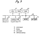
- Fig. 3 shows an example configuration of a printer serving as the image output device 1.
- a CPU 41 is a device which executes a program, to thereby perform processing described in the program.
- a ROM 42 is a memory which stores programs and data in advance.
- a RAM 43 is a memory which temporarily stores a program and data when executing the program.
- a program to be used for producing print control data from image data and a program for effecting communication in accordance with a DPS protocol and an image transfer protocol are stored, as programs to be executed by the CPU 41, in the ROM 42 or another unillustrated storage medium.
- a print engine 44 is a circuit or device which controls the output mechanism 14, to thereby perform print processing in accordance with the print control data supplied from the CPU 41.
- a USB host interface 45 corresponds to the communicator 11 shown in Fig. 1 and is a host interface circuit which is specified by the USB.
- a bus 46 is a signal channel for interconnecting the CPU 41, the ROM 42, the RAM 43, the print engine 44, the USB host interface 45, the control panel 15, and the display 16.
- the number of buses 46 and a topology of connection of the CPU 41 and the print engine 44 to the bus 46 are not limited to those shown in Fig. 3.
- control panel 15 and the display 16, which are shown in Fig. 3, are analogous to those shown in Fig. 1.
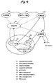
- Fig. 4 shows relationships between a plurality of functions of the image output device 1.
- a communication control function 51 is a function for effecting communication control under an image transfer protocol.
- a DPS protocol processing function 52 includes a DPS command processing function 61, which produces and interprets control information specified by the DPS protocol; an XML script generating function 62, which produces an XML script corresponding to the control information; and an XML server 63, which subjects to syntax analysis the control information described in an XML.
- the XML server 63 may be designed to enable analysis of all syntaxes in an XML or analysis of only syntaxes used in the DPS protocol. In such a case, the only requirement for the XML server 63 is to be able to discem only a tag required to describe an XML script related to the DPS protocol.
- the XML script generating function 62 may be set so as to previously store templates of XML scripts in the ROM 42 according to the types of control information items, such as commands, and to generate an XML script showing control information by editing the template.
- An image processing function 53 is a function for changing the format of image data.
- a print data generating function 54 is a function for generating print control data from image data whose format has been changed.
- a print control function 55 is a function for performing print processing in accordance with the print control data.
- a status management function 56 is a function for monitoring processing statuses of the previously-descried respective functions.
- the functions are realized by the CPU 41 executing the program.
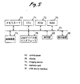
- Fig. 5 shows an example configuration of a digital camera serving as the image supply device 2.
- a CPU 71 is a device which executes a program, to thereby perform processing described by the program.
- a ROM 72 is a memory for storing programs and data in advance.
- a RAM 73 is a memory for temporarily storing a program and data when executing the program.
- a program to be used for controlling individual sections during photographing operation and a program for effecting communication and management of image data in accordance with a DPS protocol and an image transfer protocol are stored, as programs to be executed by the CPU 71, in the ROM 72 or another unillustrated storage medium.
- An imaging device 74 images a subject in accordance with a command from the CPU 71 and stores obtained image data into a memory card 75.
- the memory card 75 corresponds to the storage medium 24 shown in Fig. 1 and is a storage medium for storing image data obtained through imaging.
- Semiconductor memory or a magnetic recording device, which is fixed in a device, may be used in place of the memory card 75.
- a USB device interface 76 corresponds to the communicator 21 shown in Fig. 1 and is a device interface circuit specified by the USB.
- a bus 77 is a signal channel for interconnecting the CPU 71, the ROM 72, the RAM 73, the imaging device 74, the memory card 75, the USB device interface 76, the control panel 25, and the display 26.
- the number of buses 77 and the topology of connection of the CPU 71 to the bus 77 are not necessarily limited to those shown in Fig. 5.
- control panel 25 and the display 26, which are shown in Fig. 5, are analogous to those shown in Fig. 1.
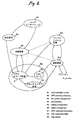
- Fig. 6 shows relationships between a plurality of functions of the image supply device 2.
- a communication control function 81 is a function for effecting communication control under an image transfer protocol.
- a DPS protocol processing function 82 includes a DPS command processing function 91, which produces and interprets control information specified by the DPS protocol; an XML script generating function 92, which produces an XML script corresponding to the control information; and an XML server 93, which subjects to syntax analysis the control information described in an XML.
- the XML server 93 may be designed to enable analysis of all syntaxes in an XML or analysis of only syntaxes used in the DPS protocol. In such a case, the only requirement for the XML server 93 is to be able to discern only a tag required to describe an XML script related to the DPS protocol.
- the XML script generating function 92 may be set so as to previously store templates of XML scripts in the ROM 72 according to the types of control information items, such as commands, and to generate an XML script showing control information by editing the template.
- a file system management function 83 is a function which stores image data as an image data file 31 in the memory card 75 serving as the storage medium 24, in accordance with a predetermined directory structure and a file structure.
- a user interface function 84 is a function for accepting operation of the control panel 25 performed by the user and displaying various information items on the display 26.
- a setting management function 85 is a function for setting requirements, such as print processing, in accordance with the user's operation.
- a status management function 86 is a function for monitoring processing statuses of the aforementioned functions. These functions are realized by the CPU 71 executing the program.
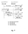
- Fig. 7 shows image output processing at the DPS protocol level.
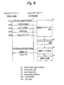
- Fig. 8 shows image output processing at the image transfer protocol level.
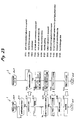
- the image supply device 2 transmits an image output job start command to the image output device 1 by way of the communication path 3 (step S1).
- the communication controller 22 produces and transmits an XML script of an image output job start command "DPS_StartJob" in accordance with the DPS protocol.
- image data which are objects of image output are specified within the XML script.
- the image output job start command "DPS_StartJob" includes the next job requirement setting information and image output information.
- the job requirement setting information include quality information for setting the quality of an image output pertaining to a current job, paper type information pertaining to a current print job, paper size information pertaining to a current print job, image format information, image optimization setting information, and page layout information.
- the image input information include cropping area information for specifying an area required when cropping operation is performed, an object ID of image data, copy number information pertaining to each image, a job ID unique to each job, path information pertaining to image data or a job specification file, and repeated supply count information pertaining to each image data (i.e., information showing the number of times identical image data are consecutively supplied to the image output device 1).
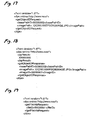
- Fig. 9 shows an example XML script of an image output job start command "DPS_StartJob".
- a job tag is a tag to be used for specifying one job.
- the tag designates both a ⁇ XX> tag and a ⁇ /XX> tag (the same also applies to any counterparts in the following descriptions).
- a jobConfig tag and a printlnfo tag are arranged below the job tag.
- the jobConfig tag is for specifying job requirement setting information.
- a quality tag In the script shown in Fig. 9, a quality tag, a paperSize tag, a paperType tag, a fileType tag, a date tag, a fileName tag, an imageOptimize tag, and a layoutItem tag are arranged below the jobConfig tag.
- the quality tag is for specifying quality information, such as a standard, a draft, or a fine.
- the paperSize tag is for specifying paper size information pertaining to a current job, such as an A4-size.
- a paper size is specified by a predetermined numeral (e.g., 02010000).
- the paperType tag is for specifying paper type information pertaining to a current job, such as standard paper or photographic paper.
- the paper size is specified by a predetermined numeral (e.g., 03020000).
- the fileType tag is for specifying image format information pertaining to a current job, such as EXIF, JPEG, TIFF, and GIF, and an image format is specified by a predetermined numeral (e.g.,04150000).
- the date tag is for specifying whether or not date information specified by a printInfo tag is to be printed.
- the fileName tag is for specifying whether or not the file path information specified by the printInfo tag is to be printed.
- the imageOptimize tag is for specifying image optimization setting information showing whether or not image optimization is to be effected.
- the layoutltem tag is for specifying a page layout of a current job. An image format is specified by a predetermined numeral (e.g., 08010000).
- the printInfo tag is for specifying image output information.
- An image tag is arranged at a position lower than the printInfo tag.
- the image tag is for specifying an image which is an object of image output.
- an imageID tag and an imageDate tag are arranged at a position lower than the image tag.
- the imageID tag is for specifying an object ID of image data which are objects of image output.
- the imageDate tag is for designating a date to be printed beside an image.
- the script shown in Fig. 9 includes only one image tag. However, in a case where a plurality of images are to be output, an image data object ID is specified for each of the plurality of images by the image tag. When a single image is to be output repetitively a plurality of times, a copies tag is arranged subsequent to an image tag of the image, whereby the number of times feeding operation to be repeated is specified.
- a dps tag shown in Fig. 9 is a tag which shows an XML script pertaining to a DPS and takes, as an attribute, an URL (Uniform Resource Locator) which is a location at which name space information to be used for DPS is stored.
- URL Uniform Resource Locator
- the communication controller 22 of the image supply device 2 transmits the XML script of the job start command in accordance with a DPS protocol. However, the communication controller 22 converts the XML script into a command of an image transfer protocol and processes that command on the image transfer protocol level.
- the communication controller 22 of the image supply device 2 first transmits a file transfer request command "RequestObjectTransfer” (step SS1) in accordance with the image transfer protocol.
- the command is transmitted to the image output device 1 by way of the USB layer and the physical layer.
- the communication controller 12 transmits a command "GetObjectInfo" for inquiring an attribute of a file to be transferred upon receipt of the file transfer request command "RequestObjectTransfer” in accordance with the image transfer protocol (step SS2).
- the command is transmitted to the image supply device 2 by way of the USB layer and the physical layer.
- the communication controller 22 transmits file information about an XML script of a command "DPS_StartJob" (a file format, a file volume, or the like) upon receipt of a command "GetObjectInfo” in accordance with the image transfer protocol (step SS3).
- the file information is transmitted to the image output device 1 by way of the USB layer and the physical layer.
- the communication controller 12 specifies the XML script upon receipt of the file information in accordance with the image transfer protocol, thereby transmitting a file acquisition command "GetObject" (step SS4).
- the file information is transmitted to the image supply device 2 by way of the USB layer and the physical layer.
- the communication controller 22 transmits a specified file (an XML script of a command "DPS_StartJob") upon receipt of the command "GetObject” in accordance with the image transfer protocol (step SS5).
- the file is transmitted to the image output device 1 by way of the USB layer and the physical layer.
- the communication controller 12 receives the file in accordance with the image transfer protocol, thereby receiving the command "DPS_StartJob" at a DPS protocol layer.
- the image output device 1 is a printer shown in Figs. 3 and 4.
- the image supply device 2 is a digital camera shown in Figs. 5 and 6
- communication under a DPS protocol is effected by the DPS protocol processing functions 52, 82 and communication control functions 51, 81.
- Communication under an image transfer protocol is performed between the communication control function 51 and the communication control function 81.
- the image output device 1 interprets an XML script of the acquired image output job start command (step S2), and image data which are objects of image output, the objects being described in the XML script, are acquired from the image supply device 2 (step S3).
- the image output device 1 controls a processing flow of the image output job. Specifically, the image output device 1 manages progress in image output processing, and information and image data, both being required for image output processing, are acquired from the image supply device 2, as required.
- the communication controller 12 specifies an image data file 31 by an object ID (corresponding to an object ID in the PTP) described in the XML script in accordance with the DPS protocol, thereby issuing the file acquisition command "DPS_GetFile" of the XML script.
- An object ID in a PTP pertaining to a certain object and an object ID in the DPS protocol may be set to a single value or different values. When the object IDs have different values, the object ID of the DPS protocol and the object ID of the PTP are mapped, as necessary.
- Fig. 10 shows an example XML script of the file acquisition command "DPS_GetFile" used in the first command.
- the getFileRequest tag is a tag showing a file acquisition command.
- the filelD tag and a buffPtr tag are arranged at positions lower than the getFileRequest tag.
- the fileID tag is for specifying an object ID of a file which is an object of acquisition.
- the buffPtr tag is for specifying a pointer of a buffer to be used for receiving the acquired file.
- the communication controller 12 converts the file acquisition command "DPS_GetFile" of the DPS protocol into a file acquisition command "GetObject” of the image transfer protocol and then transmits the thus-converted command.
- the command is transmitted to the image supply device 2 by way of the USB layer and the physical layer.
- a partial file acquisition command "DPS_GetPartialFile” to be used for acquiring a part of a file may be transmitted several times, to thereby acquire the overall file.
- the partial file acquisition command "DPS_GetPartialFile” is converted into a command "GetPartialObject" of the image transfer protocol.
- the communication controller 22 reads a file (i.e., an image data file 31) of a specified object ID upon receipt of the command "GetObject" in accordance with the image transfer protocol and transmits the file.
- the file is transmitted to the image output device 1 by way of the USB layer and the physical layer.
- the file when the communication controller 12 has received the file in accordance with the image transfer protocol, the file is also considered to have been received by the DPS protocol layer.
- the image output device 1 is the printer shown in Figs. 3 and 4 and the image supply device 2 is the digital camera shown in Figs. 5 and 6, the DPS protocol processing function 52 and the communication control function 51, both belonging to the image output device 1, and the communication control function 81 and the file system management function 83, both belonging to the image supply device 2, are used for acquiring the image data.
- step S4 when the image data are acquired, an image based on the image data is output (step S4). At that time, in the image output device 1, the output controller 13 and the output mechanism 14 perform the image output processing.
- the image output device 1 is the printer shown in Figs. 3 and 4
- the image processing function 53, the print data generating function 54, and the print control function 55 are used for image output processing.
- the image output device 1 and the image supply device 2 communicate control information pertaining to image output as a series of scripts described in a markup language by way of the communication path 3.
- correction of the protocol after prescription can be facilitated by utilization of extensibility of the syntax of a markup language while compatibility among a plurality of vendors is maintained.
- an XML which enables additional definition of a document type is used as a markup language.
- correction of the protocol after prescription can be facilitated.
- each of the communication controllers 12, 22 serves as a first entity for interpreting a DPS protocol to be used for exchanging control information pertaining to image output described in a markup language; a second entity which is located at a level lower than the first entity and interprets a PTP to be used for managing the image data file stored in the image supply device 2 and transferring the image data to the image output device 1; and a third entity which is located at a level lower than the second entity and controls a physical layer (a USB in this embodiment) of the communication path 3.
- various existing protocols can be used at hierarchical levels lower than the PTP.
- the communication controllers 12, 22 convert the DPS protocol of the first entity into the image data file management transfer protocol or vice versa in accordance with the kind of image data file management transfer protocol of the second entity (PTP in the embodiment) at a wrapper layer.
- the wrapper layer absorbs a difference between the adopted image data file management transfer protocols.
- the output controller 13 of the image output device 1 controls the processing flow of image output operation.
- the volume of information processing to be performed by the image supply device 2 essentially does not increase.
- the present system can be embodied even when the image supply device has a low level of information processing performance.
- the communication controllers 12, 22 communicate, as control information pertaining to image output and in the form of a series of scripts described in a markup language, a control command for image output processing, a response to the control command, and notification of a status of the device (including a job status).
- a control command which is on a text basis and easy to read, a response to the control command, and notification of status of the device can be communicated, and the protocol can be made easy to correct after prescription while compatibility between a plurality of vendors is maintained.
- the communication controllers 12, 22 communicate, as a series of scripts described in a markup language, a script which does not include image data to be an object of image output and includes only control information pertaining to image output.
- the control' information described in a markup language can be communicated independently of the data which are to become an object of image output, without modifying the format of data to be an object of image output from an existing format.
- the image output device 1 has an output mechanism 14 for outputting an image, and an output controller 13 which produces, from image data, control data to be used for controlling an output mechanism and controls the output mechanism on the basis of the control data.
- the image supply device 2 can be dispensed with a function for producing, from image data, control data to be used for controlling the output mechanism (e.g., a function included in a conventional printer driver used in a personal computer), and hence the image supply device 2 can be made inexpensive.
- the XML server 63 of the image output device 1 when configured to determine only a tag required to describe the control information pertaining to image output from among the tags described in a markup language, the XML server 64 can be implemented by a small-amount circuit or program, thereby rendering the image output device 1 inexpensive.
- the XML server 93 of the image supply device 2 when configured to determine only a tag required to describe the control information pertaining to image output from among the tags described in a markup language, the XML server 93 can be implemented by a small-amount circuit or program, thereby rendering the image supply device 2 inexpensive.
- the communication controllers 12, 22 store templates of scripts according to types of control information and produce scripts of control information from the templates. As a result, only portions for which templates have not been determined must be edited, thereby enabling generation of a script of control information within a short time period.
- the communication controller 22 and the communicator 21, both belonging to the image supply device 2 transmit an image output job start command to the image output device 1 as control information.
- the output controller 13 of the image output device 1 commences image output processing in accordance with the image output job start command.
- the image output can be performed by the user operating the control panel 25 of the image supply device 2.
- the image supply device 2 has the user-friendly control panel 25, operability of the control panel 25 is improved.
- the communication controller 12 of the image output device 1 transmits to the image supply device 2 a request for transmission of image data.
- the communication controller 22 of the image supply device 2 transmits the image data to the image output device 1.
- the only requirement for the image supply device 2 is to send the image data in accordance with the request from the image output device 1.
- the quantity of image processing operation of the image supply device 2 essentially does not increase, and the present system can be embodied even when the image supply device 2 has a low level of information processing performance.
- the image output system of the first embodiment has a first entity for interpreting an image output control protocol as being located at a level higher than the third entity for controlling a physical layer of the communication path, and the second entity for interpreting the image data file management protocol.
- an image can be output through use of control information pertaining to the image output suited for the DPS protocol through use of the first entity, by only changing the second entity.
- the vendor of the image supply device can construct the first entity without awareness of the type of a communication path adopted by each vendor of the image output device.
- Identical control information can be exchanged between the image supply device and the respective image output devices by combination of the thus-constructed first entity with the second entity corresponding to the selected communication path.
- a vendor of the image output device can exchange single control information between the image output device and the respective image supply devices by combination of the thus-constructed first entity with the second entity corresponding to the selected communication path. Therefore, control information compatibility pertaining to image output among a plurality of vendors is ensured.
- control information pertaining to image output is described in a markup language. Therefore, the control information is on a text basis and easy to read, and addition and correction of the control information after prescription is easy. Moreover, when control information pertaining to image output is desired to be subjected to addition or amendment after prescription, the only requirement is to correct the first entity, whereby the amount of correction required at the time of addition and modification is made smaller.
- a PTP is used as an image data file management protocol.
- various existing protocols can be used at the second and third entities corresponding to the protocols located at a level lower than the image data file management protocol.
- An image output system which communicates control information pertaining to image output can be formed within a short time period. Further, the protocol becomes easily subjected to addition or correction after prescription. The same advantage can be expected to be yielded even when a USB mass storage class is used as the image data file management protocol in place of the PTP.
- the third entity controls the USB.
- the third entity also uses a still image class as the class of the USB.
- an existing entity can be utilized for at least the third entity.
- An image output system which exchanges control information pertaining to image output can be formed within a short time period. Further, addition or correction of the protocol after prescription becomes easy.
- the communication controllers 12, 22 convert the image output control protocol of the first entity into the image data file management protocol of the same or vice versa at the wrapper layer, according to the type of the image data file management protocol of the second entity (the PTP in the embodiment).
- the wrapper layer absorbs a difference between the adopted image data file management protocols, as required. Therefore, the image output control protocol of the first entity is not corrected essentially even when the image data file management protocol of the second entity is changed to another protocol or corrected. Accordingly, addition or correction of the protocol after prescription becomes easy.
- an image output system for communicating control information pertaining to image output can be formed within a short time period.
- the output controller 13 of the image output device 1 controls a processing flow of image output.
- the quantity of information processing to be performed by the image supply device 2 essentially does not increase.
- the system can be implemented even when the image supply device 2 has a low level of information processing performance.
- the communication controllers 12, 22 communicate, as control information pertaining to image output and in the form of a series of scripts described in a markup language, a control command for image output processing, a response to the control command, and notification of a status of the device (including a job status).
- a control command which is on a text basis and easy to read, a response to the control command, and notification of status of the device can be communicated, and the protocol can be made easy to correct after prescription while compatibility between a plurality of vendors is maintained.
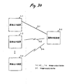
- each of the communication controllers 12, 22 has one second entity and one third entity. As illustrated in a case shown in Fig. 11 where three entities are provided, each of the communication controllers 12, 22 may have a plurality of sets, each consisting of a second entity and a corresponding third entity.
- the image output system shown in Fig. 11 has, as layers located at levels lower than the first entity, a second entity for interpreting a PTP and a third entity for controlling a physical layer at the still image class of the USB; a second entity for implementing a file system using an SCSI and a third entity for controlling a physical layer at a USB mass storage class; a second entity for implementing a file system; and a third entity for controlling a physical layer at a TCP/IP and a wireless LAN protocol.
- the image output system enables exchange of identical control information through use of any one of combinations of the plurality of image data file management protocols and a communication path.
- the image output system shown in Fig. 11 has a wrapper layer between the first entity and the respective second entities.
- the wrapper layer translates control information between the image output control protocol of the first entity and the respective image data file management protocols of the same, according to the type of the image data file management protocol of the second entity.
- the image output device 1 and the image supply device 2 of the image output system have a selector for selecting a combination for use in exchanging the control information, from among a plurality of combinations of the second and third entities.
- the selector is implemented by the communication controllers 12, 22, or the output controller 13 and the central controller 23.
- the wrapper layer (protocol converter) can absorb a difference between image data file management protocols utilized by the second entity. Therefore, the image output control protocol of the first entity is not subjected to any substantial correction even when the image data file management protocol of the first entity is changed or corrected to another protocol. Accordingly, the protocol becomes easily subjected to addition or amendment after prescription. Further, an image output system for communicating control information pertaining to an image output can be formed within a short time period. Moreover, as a result of the selector making a switch between the second and third entities, control information pertaining to an image output can be continuously communicated by utilization of a combination of the second and third entities that differs from that utilized thus far.
- a wrapper layer is provided between the DPS protocol layer and the low-level protocol layer in order to cope with variations in the low-level protocol layer.
- a function equivalent to that of the wrapper layer is imparted to the lowest layer of the DPS protocol layer, and a layer for managing a control flow of print processing of the DPS protocol may be provided as an application layer, such as another program (i.e., an entity).
- the image supply device 2 stores image data and a job specification file for specifying an image output job.
- the image output device 1 acquires the job specification file, and on the basis of the information about the job specification file, generates control information pertaining to an image output described in a markup language.
- the image data and the job specification file are stored in the storage medium 24 by the DPOF (Digital Print Order Format).
- DPOF Digital Print Order Format
- the current version of DPOF is version 1.10.
- the next version and subsequent versions, which will be proposed in future, may also be adopted.
- another standard which will yield the same working effect may also be used in place of the DPOF.
- Fig. 13 is a view for describing a directory structure of the DPOF standard.
- low-level directories located at the root level include a directory DCIM located at a level higher than the image data file, and a directory MISC located at a level higher than the job specification file.
- a directory unique to a vendor e.g., 100EPSON in the embodiment
- An image data file (e.g., IMAGE 01.JPEG) is provided in the directory.
- the directory MISC includes AUTPRINT.MRK, which is a print job specification file.
- the job specification file AUTPRINT.MRK of DPOF standard includes print job information, image source information, and print setting information.
- Fig. 14 is a view showing an example job specification file AUTPRINT.MRK of the DPOF standard.
- the AUTPRINT.MRK shown in Fig. 14 includes three jobs.
- a job ID (PRT PID), a print type (PRT TYP), the number of copies (PRT QTY), the location where image data are stored (IMG SRC), and image data format (IMG FMT) are specified for each of the jobs.
- PRT PID job ID
- PRT TYP print type
- PRT QTY the number of copies
- IMG SRC image data format
- IMG FMT image data format
- the image output device 1 and the image supply device 2, both belonging to the second embodiment, are basically identical with those described in connection with the first embodiment. However, as will be described below, the communication controller 12 and the communication controller 22, both belonging to the second embodiment, are changed.
- Fig. 15 is a view for describing image output processing at the DPS protocol level in the image output system of the second embodiment.
- Fig. 16 is a view for describing image output processing at the image transfer protocol level in the image output system of the second embodiment.
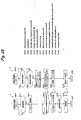
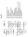
- the image supply device 2 transmits the image output job start command to the image output device 1 by way of the communication path 3 (step S21).
- the communication controller 22 in the image supply device 2 generates and transmits an XML script of an image output job start command "DPS_StartJob".
- an XML script of an image output job start command "DPS_StartJob".
- the job specification file is described in the XML script.
- the script such as that shown in Fig. 9
- the job specification file is specified by an image ID tag for specifying image data.
- An object ID of the job specification file is used for the specifying operation.
- the image output device 1 interprets the thus-acquired XML script (step S22), and the job specification file described in the XML script is acquired by way of the image supply device 2 (step S23).
- the communication controller 12 specifies the job specification file in accordance with the DPS protocol through use of an object ID (corresponding to an object ID in the PTP) described in the XML script, thereby transmitting the file information acquisition command "DPS_GetFileInfo" of the XML script.
- the communication controller 12 converts the file information acquisition command "DPS_GetFileInfo" of the DPS protocol into the file information acquisition command "GetObjectInfo” of the image transfer protocol and transmits the thus-converted command (step SS11). This command is transmitted to the image supply device 2 by way of the USB layer and the physical layer.
- the communication controller 22 upon receipt of the command "GetObjectInfo" in accordance with the image transfer protocol, transmits file information about the file of the specified object ID (step SS12).
- the file information is transmitted to the image output device 1 by way of the USB layer and the physical layer.
- the communication controller 12 upon receipt of the file information in accordance with the image transfer protocol, the communication controller 12 describes the file information as an XML script and passes the script to the DPS protocol layer.
- the communication controller 12 issues a file acquisition command "DPS_GetFile" of an XML script in accordance with the DPS protocol by designating the job specification file through use of an object ID.
- the communication controller 12 converts the file acquisition command "DPS_GetFile” of the DPS protocol into the file acquisition command "GetObject” of the image transfer protocol and transmits the thus-converted command (step SS13). This command is transmitted to the image supply device 2 by way of the USB layer and the physical layer.
- the communication controller 22 upon receipt of the command "GetObject" in accordance with the image transfer protocol, the communication controller 22 reads and transmits the file of the specified object ID (i.e., the job specification file) (step SS14).
- the file is transmitted to the image output device 1 by way of the USB layer and the physical layer.
- the communication controller 12 has received the file in accordance with the image transfer protocol, whereupon the file is also considered to have been received on the DPS protocol layer.
- the image output device 1 corresponds to the printer shown in Figs. 3 and 4
- the image supply device 2 corresponds to the digital camera shown in Figs. 5 and 6
- the DPS protocol processing function 52 and the communication control function 51 both belonging to the image output device 1
- the communication control function 81 and the file system management function 83 both belonging to the image supply device 2
- the communication controller 12 of the image output device 1 interprets the job specification file (step S24).
- the communication controller 12 of the image output device 1 acquires from the image supply device 2 image data specified by way of the jobs described in the job specification file (step S25).
- the communication controller 12 in the image output device 1 generates and transmits the command "DPS_GetObjectID", which is to be used for specifying a path and acquiring an object ID for a file of that path, according to the DPS protocol.
- Fig. 17 is a view showing an example XML script of the object ID acquisition command "DPS_GetObjectID" employed in the second embodiment.
- a getObjectIDRequest tag is a tag showing an object ID acquisition command.
- a basePathID tag and an imagePath tag are arranged at levels lower than the getObjectIDRequest tag.
- the basePathID tag is for specifying a directory which is a basis of a relative path to be specified by the imagePath tag.
- the imagePath tag is for specifying a file for which an object file is to be acquired, from the directory specified by the basePathID tag through use of the relative path.
- the communication controller 12 of the image output device 1 transmits the command "SendObjectInfo”, the command "SendObject”, the XML script and file information pertaining to the XML script in accordance with the image transfer protocol (steps SS21 to SS24). These commands, the file information, and the XML scripts are transmitted to the image supply device 2 by way of the USB layer and the physical layer.
- the communication controller 22 receives the commands, the file information, and the XML scripts in accordance with the image transfer protocol and receives the command "DPS_GetObjectID", which is an XML script, in accordance with the DPS protocol.
- the communication controller 22 of the image supply device 2 interprets the XML script of the received command "DPS_GetObjectID", specifies the object ID allocated to a file of the path specified by the command "DPS_GetObjectID”, and generates and transmits the XML script showing the object ID as a response to the command "DPS_GetObjectID”.
- Fig. 18 is a view showing an example XML script of a response to the object ID acquisition command "DPS_GetObjectID" used in the second embodiment.
- An opResult tag is for specifying a processing result code of an object ID acquisition command.
- a getObjectIDResponse tag is for specifying a return value of the result of processing of the object ID acquisition command.
- a basePathID tag, an imagePath tag, and an imageID tag are provided at levels lower than the getObjectIDResponse tag.
- the basePathID tag and the imagePath tag are identical with those specified in the command.
- the image ID tag is for specifying an object ID acquired as a result of processing of the command.
- the communication controller 22 of the image supply device 2 Upon receipt of the response to the command "DPS_GetObjectID" on the DPS protocol layer in accordance with the image transfer protocol, the communication controller 22 of the image supply device 2 first transmits a file transfer request command "RequestObjectTransfer” (step SS31). This command is transmitted to the image output device 1 by way of the USB layer and the physical layer.
- the communication controller 12 upon receipt of the file transfer request command "RequestObjectTransfer” in accordance with the image transfer protocol, transmits a command "GetObjectlnfo" for inquiring an attribute of the file to be transferred (step SS32). This command is transmitted to the image supply device 2 by way of the USB layer and the physical layer.
- the communication controller 22 upon receipt of the command "GetObjectInfo" in accordance with the image transfer protocol, transmits the file information pertaining to an XML script of the response to the command "DPS_GetObjectID" (step SS33).
- the file information is transmitted to the image output device 1 by way of the USB layer and the physical layer.
- the communication controller 12 upon receipt of the file information in accordance with the image transfer protocol, transmits the file acquisition command "GetObject" by specifying an XML script of the response (step SS34).
- the file information is transmitted to the image supply device 2 by way of the USB layer and the physical layer.
- the communication controller 22 upon receipt of the command "GetObject” in accordance with the image transfer protocol, transmits the thus-specified file (an XML script of the response to the command "DPS_GetObjectID") (step SS35).
- the file is then transmitted to the image output device 1 by way of the USB layer and the physical layer.
- the communication controller 12 upon receipt of the file in accordance with the image transfer protocol, the communication controller 12 is considered to have received the response corresponding to the command "DPS_GetObjectID" on the DPS protocol layer.
- the image output device 1 acquires the object ID of the image data file specified by the job specification file.
- the communication controller 12 specifies the image data file by the object ID acquired in accordance with the DPS protocol, thereby transmitting the file information acquisition command "DPS_GetFileInfo" of the XML script.
- Fig. 19 is a view showing an example XML script of the file information acquisition command "DPS_GetFileInfo" used in the second embodiment.
- a getFileInfoRequest tag is for specifying a file information acquisition command.
- a fileID tag is located at a level lower than the getFileInfoRequest tag.
- a fileID tag is for specifying an object ID of the file which is an object of file information acquisition.
- the communication controller 12 of the image output device 1 converts the file information acquisition command "DPS_GetFileInfo" of the DPS protocol into the file information acquisition command "GetObjectInfo” of the image transfer protocol and transmits the thus-converted command.
- the command is transmitted to the image supply device 2 by way of the USB layer and the physical layer.
- the communication controller 22 upon receipt of the command "GetObjectInfo" in accordance with the image transfer protocol, transmits the file information about the file of the specified object ID.
- the file information is transmitted to the image output device 1 by way of the USB layer and the physical layer.
- the communication controller 12 upon receipt of the file information in accordance with the image transfer protocol, the communication controller 12 describes the file information as an XML script and passes the script to the DPS protocol layer.
- Fig. 20 is a view showing an example XML script of the response to the file information acquisition command "DPS_GetFileInfo" used in the second embodiment.
- An opResult tag is for specifying a processing result code of the object ID acquisition command.
- a getFifeInfoResponse tag is for specifying a return value of the processing result of the file information acquisition command.
- a fileType tag and a fileSize tag are provided at levels lower than the getFileInfoResponse tag.
- the fileType tag is for specifying a file format of the file information.
- a fileSize tag is for specifying a file size of the file information.
- the file format is specified by any of numbers previously allocated to respective formats.
- the communication controller 12 transmits a file acquisition command "DPS_GetFile" of the XML script in accordance with the DPS protocol by specifying an image data file through use of the acquired object ID.
- the communication controller 12 converts the file acquisition command "DPS_GetFile” of the DPS protocol into a file acquisition command "GetObject” of the image transfer protocol and transmits the thus-converted command.
- the command is transmitted to the image supply device 2 by way of the USB layer and the physical layer.
- an entire file may be acquired by transmitting a plurality of times the partial file acquisition command "DPS_GetPartialFile” for acquiring a part of the file.
- the partial file acquisition command "DPS_GetPartialFile” is converted into the command "GetPartialObject" of the image transfer protocol.
- the communication controller 22 upon receipt of the command "GetObject" in accordance with the image transfer protocol, the communication controller 22 reads and transmits a file of the specified object ID (i.e., an image data file 31). This file is transmitted to the image output device 1 by way of the USB layer and the physical layer.
- the communication controller 12 upon receipt of the file in accordance with the image transfer protocol, the communication controller 12 is considered to have received the file even on the DPS protocol layer.
- the image output device 1 corresponds to the printer shown in Figs. 3 and 4
- the image supply device 2 corresponds to the digital camera shown in Figs. 5 and 6
- the DPS protocol processing function 52 and the communication control function 51 both belonging to the image output device 1
- the communication control function 81 and the file system management function 83 both belonging to the image supply device 2
- the image output device 1 Upon acquisition of the image data, the image output device 1 outputs an image based on the image data (step S26). At that time, in the image output device 1, the output controller 13 and the output mechanism 14 perform image output processing.
- the image processing function 53, the print data generating function 54, and the print control function 55 are used for image output processing.
- the job specification file stored in the image supply device 2 is transferred to the image output device 1, and the image output device 1 interprets the job specification file, thereby executing a job.
- the image supply device 2 interprets the job specification file, generates a job start command in accordance with contents of the job specification file, and transmits the command to the image output device 1.
- the image output device 1 may be arranged to interpret the job start command and execute the job.
- the image output system of the second embodiment can be embodied by combination with any of the other embodiments.
- the image supply device 2 stores image data and a job specification file for specifying an image output job (e.g., an AUTPRINT.MRK file of the DPOF in the embodiment).
- the image output device 1 acquires the job specification file, interprets the thus-specified job, and on the basis of information about the job specification file generates control information pertaining to an image output described in a markup language.
- an existing job specification file of the DPOF standard can be used, and a complicated image output job can be executed readily.
- the image supply device 2 enables specification of either the job specification file, or one or more image data sets which are objects of image output, through use of the image output job start command.
- the image output device 1 acquires the image data from the image supply device 2 in accordance with the image output job start command.
- the job specification file is specified by the image output job start command
- the job specification file is acquired from the image supply device 2 in accordance with the image output job start command.
- the image data specified by the job specification file are acquired from the image supply device 2.
- the image data which are to be an object of image output can be specified on a per-image-data basis or while being merged by the job specification file.
- Image output jobs of various patterns can be effected.
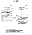
- An image output system is arranged to perform recovery processing when the image output system of the first or second embodiment has recovered from a self-unrecoverable failure (e.g., paper jam, power disconnection, or disconnection of a communication path).
- a self-unrecoverable failure e.g., paper jam, power disconnection, or disconnection of a communication path.
- the image output device 1 transmits, to the image supply device 2, resumption information for a print object allocated to a predetermined position (e.g., a top, a bottom, or the like) within a page layout during print processing serving as image output.
- a predetermined position e.g., a top, a bottom, or the like
- control information for specifying the first print object after resumption is received from the image supply device 2 along with a print job start command for newly starting print processing. Print processing is resumed from that print object. Meanwhile, the image supply device 2 receives and stores the resumption information.
- the control information for specifying a first print object after resumption is transmitted to the image output device 1 on the basis of the finally-stored resumption information along with the print job start command for newly starting print processing.
- the image output device 1 and the image supply device 2, both belonging to the third embodiment, are analogous to those of the first embodiment in terms of basic configuration, and the following functions are added.
- Fig. 21 is a status transition view of an image output device in the image output system of the third embodiment.
- the image output device 1 When no print job is present, the image output device 1 is in a no-job status (i.e., an idle state). When a print job is supplied from the image supply device 2, the image output device 1 shifts to a printing state, where print processing is performed. When the print job is completed and is not followed by any other print job, the image output device 1 shifts to the no-job state. This status is managed by the output controller 13 of the image output device 1.
- the image output device 1 When a failure has arisen in the printing state, the image output device 1 shifts to a hold state, where print processing is interrupted. When the failure is self-recoverable, the image output device 1 returns to the printing state after the failure has been eliminated, thereby resuming the interrupted print processing. Meanwhile, when the failure is self-unrecoverable, such as a paper jam or disconnection of a communication path, the image output device 1 remains in the hold state until a reset command is received. When the reset command is received, the image output device 1 discards the interrupted print job and shifts to the no-job state. When the remainder of the print job is still present or a new print job has arisen afterwards, the image output device 1 shifts to the printing state.
- the print job of the image output device 1 will disappear.
- the image output device 1 enters the no-job state.
- recovery processing procedures can be set to any of a plurality of types of procedures in accordance with the type of a failure.
- Fig. 22 is a flowchart for describing processing to be performed during normal print processing of the image output system of the third embodiment.
- Fig. 23 is a flowchart for describing example recovery processing of the image output system of the third embodiment.
- the image output device 1 performs print processing.
- job status information at the top of the new page is transmitted to the image supply device 2.
- the image output device 1 transmits, to the image supply device 2 as resumption information (i.e., job status information used for recovery processing), a job ID (corresponding to a value of "PRT PID" of DPOF) of the print job that specifies the image data first appearing in a page layout of the page of interest (new page); a path of a location where the image data are stored (corresponding to a value of "IMG SRC" of DPOF); and the number of repeated supply operations (corresponding to a value of "PRT QTY" of DPOF) (step S102).
- resumption information i.e., job status information used for recovery processing
- a job ID corresponding to a value of "PRT PID" of DPOF
- the number of repeated supply operations corresponding to a value of "PRT QTY" of DPOF
- the communication controller 12 of the image output device 1 when a page change has been performed, the communication controller 12 of the image output device 1 generates an XML script of a job status notification command "DPS_NotifyJobStatus" for notification of job status information at that time point, in accordance with a DPS protocol and transmits the script.
- the value of the job ID is surrounded by a tag ⁇ prtPid>, ⁇ /prtPid> showing the job ID;
- the value of the path of the location where the image data are stored is surrounded by a tag ⁇ imagePath>, ⁇ /imagePath> showing a path of the location where the image data are stored;
- the value of the number of repeated supply operations is surrounded by a tag ⁇ copyld>, ⁇ /copyld> showing the number of repeated supply operations.
- Fig. 24 is a view showing an example XML script of the job status notification command "DPS_NotifyJobStatus" used in the third embodiment.
- a notifyJobStatusRequest tag is for showing a job status notification command.
- a jStatus tag, a prtPid tag, an 'imagePath tag, a copyld tag, a progress tag, and a jEndReason tag are arranged at levels lower than the notifyJobStatusRequest tag.
- the value of the job specification file AUTPRINT.MRK of the DPOF acquired by the image output device 1 is used for the value specified by the prtPid tag, the value specified by the image Path tag, and the value specified by the copyld tag, whereby a job ID for the job that is being processed at that time, a path of image data, and the number of repeated supply operations are set.
- the jStatus tag is for specifying that the job is in the printing state, the no-job state, or the hold state.
- the progress tag is for specifying, in an N/T format, the total number of pages T in a job and a page number N that is now being printed.
- the jEndReason tag is for specifying a value showing a cause of termination of a job, such as a normal end, termination made by the user, or an abnormal end.
- a value is specified by the jEndReason tag.
- the job ID, the image path, and the number of repeated supply operations are specified by the prtPid tag, the image Path tag, and the copyld tag.
- the image data specified by the imageID tag in the job start command and the number of repeated supply operations specified by the copies tag may be used in the job status notification command instead.
- the image supply device 2 Upon receipt of resumption information, such as the job ID, a path of the location where image data first appearing in a page of interest is stored, and the number of times image data are to be repetitively supplied, from the image output device 1 at every a page change (step S111), the image supply device 2 updates the resumption information with that received from the image output device 1 (step S112).
- the communication controller 22 of the image supply device 2 receives the XML script that is the command "DPS_NotifyJobStatus" for each page, in accordance with the DPS protocol.
- a job ID, a path of a location where image data are stored, and the number of times image data are to be repetitively supplied are extracted from the XML script, and the thus-extracted information is stored.
- the image supply device 2 sequentially stores resumption information, such as a job ID of a print job which specifies image data at a predetermined location (in the embodiment, the top of the page), a path of a location where the image data are stored, and the number of times the image data are to be repetitively supplied, for each page for which print processing has been started. Only the updated job ID, the path of the location where the image data are stored, and the number of times the image data are to be repetitively supplied are required, and hence outdated information may be deleted.
- resumption information such as a job ID of a print job which specifies image data at a predetermined location (in the embodiment, the top of the page), a path of a location where the image data are stored, and the number of times the image data are to be repetitively supplied, for each page for which print processing has been started. Only the updated job ID, the path of the location where the image data are stored, and the number of times the image data are to be repetitively supplied are required, and hence outdated information may be deleted
- the image output device 1 shifts to a hold state and reports occurrence of a failure to the image supply device 2 (step S122).
- the image output device 1 reports disconnection by use of a battery or the power of a capacitor.
- the communication controller 12 of the image output device 1 in the event of occurrence of a failure, the communication controller 12 of the image output device 1 generates an XML script of a command "DPS_NotifyDeviceStatus" which reports the status of a device, in accordance with the DPS protocol and transmits the thus-generated command.
- the XML script of the command "DPS_NotifyDeviceStatus” the value showing the failure state is surrounded by the tag ⁇ errorStatus>, ⁇ /errorStatus>, and the value showing the cause of the failure is surrounded by a tag ⁇ reason>, ⁇ /reason> showing the cause of the failure.
- Fig. 25 is a view showing an example XML script of the device status notification command "DPS_NotifyDeviceStatus" used in the third embodiment.
- a notifyDeviceStatusRequest tag shows a device status notification command.
- An errorStatus tag, a reason tag, a disconnectEnable tag, and a capabilityChange tag are arranged at levels lower than the notifyDeviceStatusRequest tag.
- the errorStatus tag is for specifying a failure status, such as no failure, a recoverable failure, or an unrecoverable failure.
- the reason tag is for specifying the cause of a failure, such as no failure, a paper-related failure, an ink-related failure, a hardware-related failure, and a data-related failure.
- the disconnectEnable tag is for specifying whether or not connection is released.
- the capabilityChange tag is for specifying whether or not a change has arisen in the print requirements allowed by the image output device 1.
- the image supply device 2 Upon receipt from the image output device 1 of a notification relating to occurrence of a failure (step S131), the image supply device 2 reads the latest resumption information reported by the image output device 1 (e.g., a job ID, a path of a location where image data first appearing in a page of interest is stored, the number of times the image data is repetitively supplied, or the like) (step S132).
- the latest resumption information reported by the image output device 1 e.g., a job ID, a path of a location where image data first appearing in a page of interest is stored, the number of times the image data is repetitively supplied, or the like
- the communication controller 22 of the image supply device 2 receives the XML script of the command "DPS_NotifyDeviceStatus" in accordance with the DPS protocol and ascertains a failure status from the XML script.
- the image supply device 2 adds the latest resumption information to the print job start command which has already been transmitted at the time of initiation of the print job and transmits the command (step S133).
- the communication controller 22 of the image supply device 2 transmits the XML script of the command "DPS_StartJob" that has set the latest job ID, a path of a location where image data first appearing in a page of interest is stored, and the number of times the image data is repetitively supplied, in accordance with the DPS protocol.
- Fig. 26 is a view showing an example XML script of the print job start command "DPS_StartJob" obtained at resumption of the job.
- an object ID of the job specification file e.g., 00000002 in the embodiment
- a job ID showing the position for resumption, the path of the location where image data first appearing in a page of interest is stored, and the number of times the image data is repetitively supplied, are specified by the prtPid tag, the imagePath tag, and the copies tag.
- the image output device 1 Upon receipt of the print job start command (step S124), the image output device 1 transmits a request for transmission of the previously-used job specification file specified by the print job start command.
- the communication controller 12 of the image output device 1 receives the job start command "DPS_StartJob" of an XML script in accordance with the DPS protocol and issues a file acquisition command "DPS_GetFile" by specifying a job specification file.
- the image supply device 2 transmits the job specification file (step S134).
- the image output device 1 receives the job specification file (step S125).
- the communication controller 12 of the image output device 1 issues the file acquisition command "DPS_GetFile" in the DPS protocol, to thereby acquire the job specification file from the image supply device 2.
- the image output device 1 When, by reference to contents of the job specification file, the image output device 1 has found, within the job specification file, a position corresponding to the job ID specified by the print job start command, the path of the location where image data first appearing in a page of interest is stored, and the number of times the image data is repetitively supplied, the position is specified as a position where the print job is to be resumed (step S126).
- the image output device 1 resumes the print job from that position for resumption (step S127) and acquires the image data from the image supply device 2, as required (steps S127, S135).
- Fig. 27 is a view for describing resumption of printing. For instance, even when a failure has arisen during the course of printing of images 101b, 101d after printing of images 101a, 101c, a position, where printing operation is to be resumed, in the job specification file is specified on the basis of the job ID, the path, and the repetitive number, all pertaining to the image 101a first appearing in the page of interest, whereupon the print job is resumed. As shown in Fig. 27, when a plurality of images are arranged within one page, a job ID for an image of the print job that appears first is stored, and printing is resumed from that image.
- a layout shown in Fig. 27 is made by the job specification file shown in Fig. 14, a job ID "001,” a path “/DCIM/100EPSON/IMAGE01.JPG,” and the number of repeated operations "002" are stored as resumption information pertaining to IMAGE01.JPG allocated to the image 101a.
- a failure has arisen at the position shown in Fig. 27, printing is resumed with the same layout from the first job shown in Fig. 14.
- the image output device 1 changes the value of the number of repeated supply operations to be reported to the image supply device 2 to a remaining number of repeated supply operations and reports the changed value.
- the image supply device 2 changes the number of repeated supply operations to be stored to a remaining number of repeated supply operations. In this case, a position where the job is to be resumed is arranged so as to be detected by the job ID and the file path, or a corresponding number of repeated supply operations within the job specification file to be transmitted to the image output device 1 is changed similarly.
- step S141 in the event that disconnection of the communication path 3 or abnormal disconnection of power to the image output device 1 has arisen (step S141), communication between the image output device 1 and the image supply device 2 is disconnected, and hence the image supply device 2 eventually detects disconnection of communication (e.g., connection of a USB) (step S151).
- disconnection of communication e.g., connection of a USB
- the image output device 1 When the communication path 3 or power has recovered, the image output device 1 performs resetting or rebooting operation (step S123).
- the image supply device 2 detects recovery of the communication with the image output device 1 (step S152).
- the image supply device 2 transmits resumption information to the image output device 1 along with the print job start command.
- the image output device 1 resumes the print job accordingly.
- the image output device 1 transmits resumption information to the image supply device 2 on a per-page basis.
- the image output device 1 may instead automatically transmit resumption information to the image supply device 2. This case will now be described with reference to Fig. 29.
- the image output device 1 reports occurrence of the failure (step S122) and transmits resumption information to the image supply device 2 (step S161).
- the image supply device 2 receives the notification about occurrence of the failure (S131). Upon receipt of the resumption information (step S171), the image supply device 2 stores the received resumption information (step S172) and retains in a standby state until the image output device 1 recovers (step S173).
- the image supply device 2 detects recovery of the image output device 1 and transmits the resumption information to the image output device 1 along with the print job start command (step S174). On the basis of the print job start command and resumption information, the image output device 1 resumes the print job in the manner mentioned previously.
- the image output system of the third embodiment can be combined with any one of the other embodiments.
- three items such as a job ID, a path, and the number of repeated feeding operations are to be performed, are used as information showing a position for resuming printing operation. If the position for resuming printing operation can be specified accurately, only one or two of the items may be used. Further, another job status information item may also be used for resumption information.
- job status information about first image data in a page layout of a page appearing after occurrence of a page break is used for resumption information.
- job status information about final image data in a page layout of a page appearing before occurrence of a page break may also be used for resumption information.
- a print job is resumed from a location after the position matching the resumption information in a series of print jobs.
- the image output device 1 transmits, to the image supply device 2, resumption information showing an object of printing allocated to a predetermined location (in the embodiment, the page top) in a page layout during print processing performed as an image out operation.
- the image output device 1 receives, from the image supply device 2, control information for specifying an object to be printed first at the time of resumption, along with the print job start command, and resumes the print processing from the object.
- the image supply device 2 receives and stores the resumption information.
- the image supply device 2 transmits, to the image output device 1, control information for specifying the object on the basis of the latest resumption information in conjunction with the print job start command.
- the image output device 1 is reset, and print processing can be resumed accurately after recovery even when information has disappeared as a result of resetting of the image output device 1.
- the third embodiment for example, only when the image output device 1 has detected a failure, resumption information is transmitted to the image supply device 2. As a result, frequent exchange of resumption information for recovery purpose is not required. Therefore, print processing can be accurately resumed after recovery without involvement of an increase in processing during normal operation.
- the image output device 1 transmits resumption information to the image supply device 2 on a per-page basis. As a result, even when transmission of resumption information has failed in the event of occurrence of a failure, print processing can be resumed accurately after recovery.
- the resumption information includes at least one of a job ID of: a print job pertaining to an object of printing allocated to a predetermined position in a page layout; information showing a location in the image supply device 2 where the object of printing is stored; and the number of times the object of printing is to be repetitively supplied.
- the image supply device 2 uses, for resumption information, at least the number of times an object of printing is to be repetitively supplied.
- the number of repeated supply operations is changed to a remaining number of repeated supply operations.
- the image output device 1 when the image output device 1 has detected a failure, detection of the failure is reported to the image supply device 2. Subsequently, print processing is aborted.
- the image supply device 2 receives a reset command, resumption information is transmitted to the image output device 1 along with the print job command. As a result, printing is resumed in response to a reset command after thorough recovery, and the print processing can be resumed accurately after recovery.
- An image output system has a plurality of image output devices 1-1 to 1-n.
- an alternative image output device 1-k is retrieved, and image output processing is continuously performed by the alternative image output device 1-k.
- Fig. 30 is a block diagram showing the configuration of the image output system of the fourth embodiment.
- An image supply device 2-1 is analogous to the previously-described image supply device 2 and has, as a communicator 21, one or more communicators which can be connected to the plurality of image output devices 1-1 to 1-n by way of a cable communication path 3-1 or wireless communication paths 3-2 to 3-n.
- Information for specifying the first object of printing when printing is resumed is transmitted to an image output device 1-k (k ⁇ j) different from the image output device 1-j that has caused a failure, by way of any one of the communicators.
- the information described in connection with the third embodiment may be transmitted as information to be transmitted to the different image output device 1-k (k ⁇ j), thereby resuming printing in the manner as mentioned in connection with the third embodiment.
- the different image output device 1-k can accurately resume printing. Further, printing can be accurately, immediately resumed by the other image output device 1-k without awaiting recovery. This effect can be yielded similarly by a pull-printing type system.
- the image supply device 2-1 selects any one from the remaining image output devices 1-2 to 1-n and, by way of any communicator, transmits information for specifying the first object of printing at the time of resumption of printing.
- the image output device 1-k that has received the information specifies the location where the job is to be resumed, thereby initiating print processing from that location.
- the image supply device 2-1 may select an image output device 1-r capable of interpreting an image output control protocol (e.g., the previously-described DPS protocol and PTP) employed by the image output device 2-1 from among the plurality of image output devices 1-2 to 1-n and may transmit, to the image output device 1-r, information for specifying an object to be printed first after the resumption.
- an image output control protocol e.g., the previously-described DPS protocol and PTP
- the image supply device 2-1 may select, from among the plurality of image output devices 1-2 to 1-n, the image output device 1-r capable of performing printing operation under printing requirements specified by the interrupted print job, and may transmit information for specifying an object to be printed first after the resumption at the image output device 1-r. As a result, printing can be resumed in the same printing state as that achieved by the original image output device even when another image output device is used.
- Such printing requirements include a paper size, a paper type, color correction processing unique to a vendor, and superimposed printing of a frame image (i.e., a frame image is printed so as to overlap an image based on image data).
- the image output system of the fourth embodiment can be combined with any one of the other embodiments.
- the image supply device 2-1 may select a communicable second entity.
- the image supply device 2-1 may select a communicable second entity.
- the selector of the image supply device 2-1 may be configured to select second and third entities for each type of control information about image output the first entity attempts to transmit.
- an optimum low-level layer is used for each type of control information. Consequently, features of the respective image data file management protocols can be used in combination, thereby improving efficiency of communication and control.
- the selector of the image supply device 2-1 may select second and third entities differing from the current second and third entities, thereby switching the second and third entities to and from which control information about the image output is to be communicated.
- the selector of the image supply device 2-1 can continuously exchange control information about image output by utilization of other second and third entities of the image supply device 2-1. Consequently, the reliability of operation of the image output system is enhanced.
- the communicator 21 and the communication controller 22 of the image supply device 2-1 may be provided with a priority table showing the sequence of priority of a plurality of pairs of second and third entities.
- the selector of the image supply device 2-1 first selects a second entity having a higher priority in the priority table.
- second and third entities having higher priority levels may be selected.
- the selector of the image supply device 2-1 selects second and third entities in accordance with previously-set priority levels. Consequently, the second and third entities of the image supply device 2-1 can be selected from the user's desired viewpoint from among various viewpoints, such as a communication speed, reliability, or the like.
- control information is described through use of XML which is one of the markup languages.
- XML which is one of the markup languages.
- SGML Standard Generalized Markup Language
- SGML Standard Generalized Markup Language
- the PTP and the USB are used at hierarchical levels lower than the DPS protocol level.
- another protocol such as a TCP/IP (Transmission Control Protocol/Internet Protocol) may also be used.
- TCP/IP Transmission Control Protocol/Internet Protocol
- a LAN cable, Bluetooth, a wireless LAN, or the like may also be used as a transmission medium.
- command names and the tag names of the DPS protocol used in the respective embodiments are not limited to those mentioned previously; other names may also be employed. Commands of the DPS protocol may also be embodied by other commands having the same function or a combination thereof.
- the image output device 1 can be embodied as a printer, and the image supply device 2 can be embodied as a digital camera for recording a moving image and/or a still image.
- the image output device 1 may also be embodied as another recording device for recording an image on a medium such as paper or a display for projecting an image of light such as a display.
- the image supply device 2 may also be embodied as an electronic device having a built-in digital camera or an electronic device which receives an image signal.
- Such an electronic device includes a mobile telephone, a PDA, a music player, a TV set, a video recording/reproducing apparatus, a picture phone, a videoconferencing system, etc.
- the image supply device 2 may be embodied as a device having portability or a device not having much portability.
- a notice indicating that connection with the image output device 1 can be released may be transmitted from the image output device 1 to the image supply device 2.
- USB mass storage class may also be employed as the image data file management transfer protocol in place of the PTP.
- the images described in connection with the embodiments may be embodied as text images in addition to picture images.
- the object of image output may be a text, e.g., a title table or lyrics of a music album, such as a music CD or a music MD.
- the image supply device 2 or the image output device 1 acquires text data from a distribution server on the Internet in accordance with the information recorded on a music album.
- the image output device 1 acquires a job specification file, analyzes the job specification file, and executes an image output job.
- the image supply device 2 may analyze a job specification file, produce an image output job start command as control information pertaining to image output, and transmit the command to the image output device 1, thereby executing an image output job.
Landscapes
- Engineering & Computer Science (AREA)
- Multimedia (AREA)
- Signal Processing (AREA)
- Accessory Devices And Overall Control Thereof (AREA)
- Studio Devices (AREA)
- Facsimiles In General (AREA)
- Television Signal Processing For Recording (AREA)
- Processing Or Creating Images (AREA)
Abstract
Description
Claims (35)
- An image processing method, performed by an image output device connected to an image supply device storing image data, via a communication path through which the image data is communicated, the method comprising steps of:receiving, from the image supply device, a control information item including a script for image processing with respect to the image data, the script being described by a markup language; andperforming the image processing with respect to the image data based on the control information item.
- The image processing method as set forth in daim 1, wherein the image output device is a printer, and the image supply device is a digital camera.
- The image processing method as set forth in claim 1, wherein the markup language enables additional definition of a document form.
- The image processing method as set forth in claim 3, wherein the markup language is one of a standard generalized markup language (SGML), an extensible markup language (XML), and a language having a hierarchical compatibility with the SGML or the XML.
- The image processing method as set forth in claim 1, wherein the script includes a control command for the image processing, a response for the control command, and a notification of a status of the image output device, which are described by the markup language.
- The image processing method as set forth in claim 1, wherein the control information item does not contain the image data therein.
- The image processing method as set forth in claim 1, further comprising a step of generating a control signal for controlling an image output mechanism, based on the control information item and the image data.
- The image processing method as set forth in claim 1, further comprising a step of providing a parser, which analyzes a syntax of the markup language to interpret a tag of the markup language which is related to the image processing.
- An image processing method, performed by an image output device connected to an image supply device storing image data, via a communication path, the method comprising steps of:storing templates each associated with at least one control information item;communicating, with the image supply device, a control information item including a script for image processing, which is described by a markup language and generated from one of the templates based on the control information item;receiving image data stored in the image supply device, based on the script; andperforming the image processing with respect to the image data, based on the script.
- An information processing method, performed by an image supply device connected to an image output device via a communication path, the method comprising steps of:receiving, from the image output device, a status information item indicating a status of the image output device; andgenerating a control information item including a script for image processing performed by the image output device, which is described by a markup language.
- An information processing method, performed by an image supply device connected to an image output device via a communication path, the method comprising steps of:communicating, with the image output device, a control information item including a script for image processing, which is described by a markup language; andproviding a parser, which analyzes a syntax of the markup language to interpret a tag of the markup language which is related to the image processing.
- An image processing method, performed by an image supply device connected to an image supply output via a communication path, the method comprising steps of:storing templates each associated with at least one control information item; andcommunicating, with the image output device, a control information item including a script for image processing, which is described by a markup language and generated from one of the templates based on the control information item.
- An image processing method, performed by an image supply device connected to an image supply output via a communication path through which the image data is communicated, the method comprising steps of:storing a job specification file for specifying an image processing job and the image data;generating, based on the job specification file, a script including a command for initiating the image processing job, the script being described by a markup language; andtransmitting the script to the image output device.
- An image processing method performed by an image supply device storing image data and an image output device performing image processing with respect to the image data, which are connected via a communication path through which the image data is communicated, the method comprising steps of:communicating, between the image supply device and the image output device, a control information item including a script for the image processing, which is described by a markup language;transmitting the image data to the image output device, based on the script; andperforming the image processing, at the image output device, with respect to the image data.
- The image processing method as set forth in claim 14, wherein the image output device controls a flow of the image processing.
- The image processing method as set forth in claim 15, further comprising a step of transmitting, from the image supply device to the image output device, a job start command as the script, in a case where a predetermined actuation on a control panel of the image supply device is detected,
wherein the image output device performs the image processing in response to the job start command. - The image processing method as set forth in claim 16, further comprising steps of:wherein the image supply device transmits the image data in response to the transmission request.generating, at the image output device, a transmission request for image data designated by the job start command; andtransmitting the transmission request to the image supply device,
- The image processing method as set forth in claim 14, wherein the image supply device controls a flow of the image processing.
- The image processing method as set forth in claim 18, further comprising a step of transmitting, from the image output device to the image supply device, a job start command as the script, in a case where a predetermined actuation on a control panel of the image output device is detected,
wherein the image supply device transmits the image data in response to the job start command. - An image processing method performed by an image supply device storing image data and an image output device performing image processing with respect to the image data, which are connected via a communication path through which the image data is communicated, the method comprising steps of:storing, in the image supply device, a job specification file for specifying at least one image processing job and;transmitting the job specification file to the image output device;generating, at the image output device, a control information item described by a markup language, based on the job specification file; andtransmitting the control information item to the image supply device.
- The information processing method as set forth in claim 20, wherein:the image supply device specifies one of the image data and the job specification file, by a script including a job start command described by the markup language;the image output device determines which one of the image data and the job specification file is specified by the job start command;the image output device acquires the image data from the image supply device, in a case where the image output device determines that the job start command specifies the image data; andthe image output device first acquires the job specification file from the image supply device, in a case where the image output device determines that the job start command specifies the job specification file, and then acquires the image data specified by the job specification file, from the image supply device.
- The image processing method as set forth in claim 20, wherein the job specification file includes at least one processing condition information item each associated with one of the at least one image processing job.
- The image processing method as set forth in claim 20, wherein the job specification file is stored by a digital print order format (DPOF) standard.
- An image processing method performed by an image supply device storing image data and an image output device performing image processing with respect to the image data, which are connected via a communication path through which the image data is communicated, the method comprising steps of:transmitting, from the image output device to the image supply device, a status information item pertaining to an operation status of the image output device, at least a part of which is described by a markup language; andgenerating, at the image supply device, a control information item pertaining to a resuming operation of the image output device, at least a part of which is described by a markup language.
- The image processing method as set forth in claim 24, wherein the status information item includes a resumption information item which specifies a printed object which is allocated at a predetermined position in a page layout, and the method further comprises steps of:storing the resumption information item in the image supply device;transmitting, as the control information item, a first script including a job start command for resuming a print operation at the image output device, and a second script specifying one image data to be first printed when the print operation is resumed, based on the resumption information item, in a case where the state information item indicates that the print operation is halted; andresuming the print operation from the printed object, in accordance with the first script and the second script.
- The image processing method as set forth in claim 25, wherein the resumption information item is transmitted only in a case where the print operation is halted.
- The image processing method as set forth in claim 25, wherein the resumption information item is transmitted every time a page break is conducted during the print operation.
- The image processing method as set forth in claim 25, wherein the resumption information item includes at least one of a path information item indicating where the one image data is stored in the image supply device and a number information item indicating how many times the printed object is to be supplied to the image output device repetitively.
- The image processing method as set forth in claim 28, wherein the number information item is corrected so as to indicate a remained number of the repetitive supply of the one image data before the one image data is supplied to the image output device, in a case where a page break is conducted during the supply of the one image data.
- The image processing method as set forth in claim 25, further comprising steps of:detecting, at the image output device, a first condition for halting the print operation;transmitting, as the status information item, a third script indicating that the first condition is detected;halting the print operation after the third script is transmitted;detecting, at the image output device, a second condition for resuming the print operation; andtransmitting, as the status information item, a fourth script indicating that the second condition is detected.
- An image processing system, comprising:wherein each of the image supply device and the image output device has a communication controller operable to communicate a control information item including a script for the image processing which is described by a markup language.an image supply device, operable to store image data; andan image output device, connected to the image supply device via a communication path through which the image data is communicated, and operable to perform image processing with respect to the image data,
- An image output device, comprising:a communicator, connected to an image supply device storing image data via a communication path through which the image data is communicated;a communication controller, operable to communicate, with the image supply device, a control information item including a script for image processing, which is described by a markup language; anda processor, operable to perform the image processing to output an image based on the image data and the control information item.
- An image supply device, comprising:a storage, which stores image data;a communicator, connected to an image output device performing image processing with respect to the image data via a communication path through which the image data is communicated; anda communication controller, operable to communicate, with the image output device, a control information item including a script for the image processing which is described by a markup language.
- A computer program product comprising a computer program which causes a computer to serve as the communication controller in the image output device as set forth in claim 32.
- A computer program product comprising a computer program which causes a computer to serve as the communication controller in the image supply device as set forth in claim 33.
Applications Claiming Priority (4)
| Application Number | Priority Date | Filing Date | Title |
|---|---|---|---|
| JP2002360983 | 2002-12-12 | ||
| JP2002360983 | 2002-12-12 | ||
| JP2003070525 | 2003-03-14 | ||
| JP2003070525 | 2003-03-14 |
Publications (2)
| Publication Number | Publication Date |
|---|---|
| EP1429533A2 true EP1429533A2 (en) | 2004-06-16 |
| EP1429533A3 EP1429533A3 (en) | 2005-12-07 |
Family
ID=32328387
Family Applications (1)
| Application Number | Title | Priority Date | Filing Date |
|---|---|---|---|
| EP03028704A Withdrawn EP1429533A3 (en) | 2002-12-12 | 2003-12-12 | Image processing method and image processing system using the same |
Country Status (3)
| Country | Link |
|---|---|
| US (2) | US7864350B2 (en) |
| EP (1) | EP1429533A3 (en) |
| JP (1) | JP2009259268A (en) |
Cited By (2)
| Publication number | Priority date | Publication date | Assignee | Title |
|---|---|---|---|---|
| EP1792742A4 (en) * | 2004-08-25 | 2009-01-14 | Canon Kk | Print system, image supply device, print device, and control method thereof |
| WO2010001942A1 (en) | 2008-06-30 | 2010-01-07 | Canon Kabushiki Kaisha | Configuring apparatus, image output apparatus, methods of controlling the same, and program |
Families Citing this family (23)
| Publication number | Priority date | Publication date | Assignee | Title |
|---|---|---|---|---|
| JP3869714B2 (en) * | 2001-12-17 | 2007-01-17 | 三洋電機株式会社 | Image recording device |
| JP3728277B2 (en) * | 2002-06-04 | 2005-12-21 | キヤノン株式会社 | DIGITAL CAMERA, ITS CONTROL METHOD, AND PRINT SYSTEM |
| JP3728276B2 (en) | 2002-06-04 | 2005-12-21 | キヤノン株式会社 | Printing apparatus, control method therefor, and printing system |
| JP4125173B2 (en) * | 2003-04-23 | 2008-07-30 | キヤノン株式会社 | Information processing apparatus connection control method, information processing apparatus, and computer program |
| JP4136771B2 (en) | 2003-04-23 | 2008-08-20 | キヤノン株式会社 | COMMUNICATION SYSTEM, COMMUNICATION DEVICE, ITS CONTROL METHOD, AND COMPUTER PROGRAM |
| JP4125172B2 (en) | 2003-04-23 | 2008-07-30 | キヤノン株式会社 | Wireless communication system, wireless communication apparatus, control method therefor, and computer program |
| US7424525B2 (en) * | 2003-06-30 | 2008-09-09 | Microsoft Corporation | Managing headless computer systems |
| JP2005131915A (en) * | 2003-10-30 | 2005-05-26 | Seiko Epson Corp | Printing apparatus, printing method, and program for printing apparatus |
| JP2005208723A (en) * | 2004-01-20 | 2005-08-04 | Seiko Epson Corp | Printing apparatus and medium type setting method |
| BRPI0511021A (en) * | 2004-05-12 | 2007-11-27 | Samsung Electronics Co Ltd | multimedia data provision method for direct printing, direct printing method, imaging provider, and printing device |
| US20050254085A1 (en) * | 2004-05-12 | 2005-11-17 | Koji Oshikiri | Image forming system |
| KR100601690B1 (en) * | 2004-07-06 | 2006-07-14 | 삼성전자주식회사 | Wireless LAN based wireless printing system and method |
| KR100664926B1 (en) * | 2004-10-06 | 2007-01-04 | 삼성전자주식회사 | Apparatus and Method for Direct Printing |
| KR100727927B1 (en) | 2004-11-02 | 2007-06-13 | 삼성전자주식회사 | Printing method using ordering file and printing system, image feeder and printing device using the method |
| JP4592490B2 (en) * | 2005-05-16 | 2010-12-01 | 株式会社リコー | Imaging device |
| JP4760415B2 (en) * | 2006-02-06 | 2011-08-31 | セイコーエプソン株式会社 | Computer device driver implementation method |
| JP4886463B2 (en) | 2006-10-20 | 2012-02-29 | キヤノン株式会社 | Communication parameter setting method, communication apparatus, and management apparatus for managing communication parameters |
| KR101022478B1 (en) * | 2006-12-26 | 2011-03-15 | 삼성전자주식회사 | Method for processing multiple print job and print system, image supply device and print device thereof |
| JP4918904B2 (en) | 2007-10-01 | 2012-04-18 | ブラザー工業株式会社 | Print data generation apparatus and computer program |
| JP5957935B2 (en) | 2012-02-14 | 2016-07-27 | セイコーエプソン株式会社 | CONTROL DEVICE, CONTROL DEVICE CONTROL METHOD, AND PROGRAM |
| US8913263B2 (en) | 2013-02-27 | 2014-12-16 | Ricoh Company, Ltd. | Page level recovery graphical user interface |
| US9626138B2 (en) | 2014-10-20 | 2017-04-18 | Ricoh Company, Ltd. | Reconstruction of suspended print jobs |
| JP7422453B2 (en) * | 2019-10-02 | 2024-01-26 | キヤノン株式会社 | Image forming apparatus and its control method |
Family Cites Families (63)
| Publication number | Priority date | Publication date | Assignee | Title |
|---|---|---|---|---|
| JPH03224778A (en) | 1990-01-31 | 1991-10-03 | Hitachi Ltd | Printing apparatus |
| JPH04188348A (en) | 1990-11-22 | 1992-07-06 | Tokyo Electric Co Ltd | Communication data conversion device |
| JP2915774B2 (en) * | 1994-02-24 | 1999-07-05 | キヤノン株式会社 | Print processing apparatus and method |
| JPH0830455A (en) | 1994-07-18 | 1996-02-02 | Hitachi Ltd | Object-oriented information processing system |
| JPH0976606A (en) | 1995-09-19 | 1997-03-25 | Hitachi Ltd | Printing failure processing method and printing system |
| JP3747108B2 (en) * | 1996-02-02 | 2006-02-22 | キヤノン株式会社 | Digital imaging apparatus and control method thereof |
| EP0843423A4 (en) | 1996-03-07 | 2004-12-15 | Nippon Telegraph & Telephone | DATA RELAY TRANSMITTER, DATA TRANSMISSION SYSTEM, AND DATA TRANSMISSION METHOD |
| JPH10164172A (en) | 1996-11-28 | 1998-06-19 | Nippon Denki Ido Tsushin Kk | Text data transmission method |
| JP3768644B2 (en) | 1997-06-23 | 2006-04-19 | キヤノン株式会社 | Data transfer apparatus and method |
| EP0859324B1 (en) * | 1997-02-14 | 2007-01-03 | Canon Kabushiki Kaisha | Data transmission apparatus, system and method, and image processing apparatus |
| DE69840972D1 (en) * | 1997-02-14 | 2009-08-27 | Canon Kk | Apparatus, system and method for data transmission and apparatus for image processing |
| TW384611B (en) * | 1997-02-14 | 2000-03-11 | Canon Kk | Data communication apparatus and method |
| EP0859323B1 (en) * | 1997-02-14 | 2007-03-21 | Canon Kabushiki Kaisha | Data transmission apparatus, system and method, and image processing apparatus |
| EP0859326A3 (en) * | 1997-02-14 | 1999-05-12 | Canon Kabushiki Kaisha | Data transmission apparatus, system and method, and image processing apparatus |
| JPH10293661A (en) | 1997-04-21 | 1998-11-04 | Ricoh Co Ltd | Network printer system |
| JP3646471B2 (en) | 1997-05-14 | 2005-05-11 | 日本電信電話株式会社 | Information providing method, personal adaptation information providing server, and storage medium storing information providing program |
| JPH11112722A (en) * | 1997-09-30 | 1999-04-23 | Minolta Co Ltd | Image forming device and image forming system |
| JPH11196099A (en) | 1997-12-25 | 1999-07-21 | Canon Inc | Data communication method and device |
| JP3059703B2 (en) | 1998-04-21 | 2000-07-04 | 株式会社ホンダ・エクスプレス | Container and container loading plate |
| JP4136086B2 (en) * | 1998-06-30 | 2008-08-20 | 富士通株式会社 | Printer control apparatus and printing system |
| JP2000105676A (en) | 1998-07-31 | 2000-04-11 | Canon Inc | Information processing apparatus, information processing method, and storage medium storing computer readable program |
| JP4392919B2 (en) * | 1998-12-24 | 2010-01-06 | キヤノン株式会社 | Print control apparatus, print control method, recording medium storing print control program, and print control program product |
| US6806978B1 (en) * | 1999-05-14 | 2004-10-19 | Konica Corporation | Image pick-up printing apparatus |
| JP3716676B2 (en) * | 1999-07-13 | 2005-11-16 | コニカミノルタビジネステクノロジーズ株式会社 | Image composition output device |
| JP2001127986A (en) | 1999-10-29 | 2001-05-11 | Canon Inc | Image processing apparatus, image processing method, and storage medium |
| US6581094B1 (en) | 1999-11-02 | 2003-06-17 | Sun Microsystems, Inc. | Apparatus and method for identifying a digital device based on the device's uniform device descriptor file that specifies the attributes of the device in a XML document in a networked environment |
| JP3832702B2 (en) | 1999-11-08 | 2006-10-11 | セイコーエプソン株式会社 | Printing system |
| JP2001177712A (en) | 1999-12-15 | 2001-06-29 | Fuji Xerox Co Ltd | Image processor and medium with image to be formed therein |
| JP3893442B2 (en) * | 2000-01-14 | 2007-03-14 | 富士フイルム株式会社 | Print ordering method and apparatus, and printing apparatus |
| JP3509684B2 (en) | 2000-02-02 | 2004-03-22 | 日本電気株式会社 | Connection control device, connection control method, recording medium storing connection control program, and data communication system |
| JP2001216522A (en) | 2000-02-04 | 2001-08-10 | Fuji Photo Film Co Ltd | Method and system for generating printing data |
| JP2001238156A (en) * | 2000-02-21 | 2001-08-31 | Seiko Epson Corp | Image printing system and digital camera used therein |
| JP2001268305A (en) | 2000-03-16 | 2001-09-28 | Canon Inc | Facsimile apparatus and image data conversion method thereof |
| JP2001290612A (en) | 2000-04-07 | 2001-10-19 | Nec Corp | Print system |
| US7191236B2 (en) * | 2000-05-02 | 2007-03-13 | Canon Kabushiki Kaisha | Transparent telecommunications system and apparatus |
| AUPQ724700A0 (en) * | 2000-05-02 | 2000-05-25 | Canon Kabushiki Kaisha | Printing using secure pickup |
| JP4123403B2 (en) | 2000-05-23 | 2008-07-23 | 富士フイルム株式会社 | Information communication system, information communication method, and printer |
| US7414746B2 (en) * | 2000-05-23 | 2008-08-19 | Fujifilm Corporation | Image data communication method |
| GB2363217B (en) * | 2000-06-06 | 2002-05-08 | Oracle Corp | Data file processing |
| JP3520859B2 (en) * | 2000-09-01 | 2004-04-19 | セイコーエプソン株式会社 | Image file output image adjustment |
| JP4590080B2 (en) | 2000-09-12 | 2010-12-01 | キヤノン株式会社 | Printer system and control method thereof |
| JP2002103746A (en) * | 2000-09-28 | 2002-04-09 | Toshiba Tec Corp | How to print XML data compatible barcodes |
| US6834297B1 (en) | 2000-10-06 | 2004-12-21 | Redline Networks, Inc. | Web resource transfer acceleration system and method |
| US7039727B2 (en) | 2000-10-17 | 2006-05-02 | Microsoft Corporation | System and method for controlling mass storage class digital imaging devices |
| EP1204030A1 (en) | 2000-11-02 | 2002-05-08 | Caplin Systems Limited | Extending hypermedia documents by adding tagged attributes |
| JP4037064B2 (en) * | 2000-11-06 | 2008-01-23 | 株式会社リコー | Image processing apparatus, image processing method, and program for causing computer to execute the method |
| JP3848133B2 (en) * | 2000-11-17 | 2006-11-22 | キヤノン株式会社 | Image forming apparatus and image forming method for processing data described in structured description language |
| JP2002259100A (en) * | 2000-12-28 | 2002-09-13 | Ricoh Co Ltd | Printing system |
| JP3919548B2 (en) | 2001-02-01 | 2007-05-30 | キヤノン株式会社 | Digital camera and printing method |
| US7310156B2 (en) * | 2001-02-01 | 2007-12-18 | Canon Kabushiki Kaisha | Printing system, printing method, digital camera, storage medium and program for printing method, and printing control apparatus |
| JP2002237972A (en) | 2001-02-07 | 2002-08-23 | Canon Inc | Digital camera and control method |
| JP3520860B2 (en) * | 2001-02-09 | 2004-04-19 | セイコーエプソン株式会社 | Image file output image adjustment |
| JP4123726B2 (en) * | 2001-02-26 | 2008-07-23 | セイコーエプソン株式会社 | Digital still camera |
| US7656426B2 (en) * | 2001-04-06 | 2010-02-02 | Sony Corporation | Digital camera and data transfer method from a record medium |
| JP3854817B2 (en) * | 2001-04-19 | 2006-12-06 | キヤノン株式会社 | Image processing apparatus, image processing apparatus control method, and storage medium |
| JP2002330394A (en) | 2001-05-07 | 2002-11-15 | Canon Inc | Digital camera direct printing system, digital camera, digital camera direct printing method |
| JP2003046707A (en) * | 2001-07-31 | 2003-02-14 | Canon Inc | Imaging device, information processing device and control method thereof, image processing device and method, and image processing system |
| JP3884942B2 (en) * | 2001-10-31 | 2007-02-21 | キヤノン株式会社 | IMAGING DEVICE, SYSTEM HAVING IMAGING DEVICE AND RECORDING DEVICE AND CONTROL METHOD THEREOF |
| JP3840091B2 (en) * | 2001-10-31 | 2006-11-01 | キヤノン株式会社 | IMAGING DEVICE, SYSTEM HAVING IMAGING DEVICE AND RECORDING DEVICE AND CONTROL METHOD THEREOF |
| US6661978B2 (en) * | 2002-01-16 | 2003-12-09 | Xerox Corporation | Method and apparatus for automated job recovery |
| JP3728276B2 (en) | 2002-06-04 | 2005-12-21 | キヤノン株式会社 | Printing apparatus, control method therefor, and printing system |
| JP3673779B2 (en) | 2002-08-05 | 2005-07-20 | キヤノン株式会社 | Image supply apparatus, control method therefor, and print system |
| US8102558B2 (en) * | 2002-08-05 | 2012-01-24 | Canon Kabushiki Kaisha | Image supply apparatus, control method therefor, and printing system |
-
2003
- 2003-12-12 US US10/734,375 patent/US7864350B2/en active Active
- 2003-12-12 EP EP03028704A patent/EP1429533A3/en not_active Withdrawn
-
2007
- 2007-05-23 US US11/805,605 patent/US20070222862A1/en not_active Abandoned
-
2009
- 2009-07-22 JP JP2009170925A patent/JP2009259268A/en not_active Withdrawn
Cited By (7)
| Publication number | Priority date | Publication date | Assignee | Title |
|---|---|---|---|---|
| EP1792742A4 (en) * | 2004-08-25 | 2009-01-14 | Canon Kk | Print system, image supply device, print device, and control method thereof |
| US7764393B2 (en) | 2004-08-25 | 2010-07-27 | Canon Kabushiki Kaisha | Print system, image supply device, print apparatus, and control method thereof |
| WO2010001942A1 (en) | 2008-06-30 | 2010-01-07 | Canon Kabushiki Kaisha | Configuring apparatus, image output apparatus, methods of controlling the same, and program |
| CN102077576A (en) * | 2008-06-30 | 2011-05-25 | 佳能株式会社 | Configuring apparatus, image output apparatus, methods of controlling same, and program |
| EP2294810A4 (en) * | 2008-06-30 | 2013-03-27 | Canon Kk | Configuring apparatus, image output apparatus, methods of controlling the same, and program |
| US8902445B2 (en) | 2008-06-30 | 2014-12-02 | Canon Kabushiki Kaisha | Configuring apparatus, image output apparatus, methods of controlling the same, and program |
| US9154651B2 (en) | 2008-06-30 | 2015-10-06 | Canon Kabushiki Kaisha | Configuring apparatus, image output apparatus, methods of controlling the same, and program |
Also Published As
| Publication number | Publication date |
|---|---|
| US20070222862A1 (en) | 2007-09-27 |
| US7864350B2 (en) | 2011-01-04 |
| EP1429533A3 (en) | 2005-12-07 |
| US20040179105A1 (en) | 2004-09-16 |
| JP2009259268A (en) | 2009-11-05 |
Similar Documents
| Publication | Publication Date | Title |
|---|---|---|
| US20070222862A1 (en) | Image processing method and image processing system using the same | |
| US7400421B2 (en) | Image processing method and image processing system using the same | |
| US7426051B2 (en) | Image processing method and image processing system using the same | |
| EP1429532B1 (en) | Image processing method and image processing system using the same | |
| RU2293027C2 (en) | Device for feeding image, registration system and registration control method | |
| RU2363977C2 (en) | Recording system and method of controlling said recording system | |
| CN100558559C (en) | Print system | |
| KR100861158B1 (en) | Information processing apparatus, image forming apparatus, method therefor, and system | |
| JP2004297785A (en) | Image forming apparatus for delivering data and information processing apparatus for acquiring data from the image forming apparatus | |
| JP2004310672A (en) | Data input device and image output system | |
| JP2004254296A (en) | Recording apparatus, communication apparatus, recording system, and control method therefor. | |
| EP1792742B1 (en) | Print system, image supply device, print device, and control method thereof | |
| JP3673779B2 (en) | Image supply apparatus, control method therefor, and print system | |
| US8179538B2 (en) | Image processing apparatus, information processing apparatus and control method | |
| EP1653341A2 (en) | Printing method using ordering file, and print system, image supply device and print device employing the method | |
| US20050174600A1 (en) | Image output system, image supply device, image output device, and image output method | |
| JP4314990B2 (en) | Direct printing system, printer, digital camera, control program, and image printing method | |
| JP2004237713A (en) | Image output system, image output device, image supply device, control program, and image output method | |
| JP2004320716A (en) | Image output system, image supply device, image output device, and image output method | |
| JP2004318818A (en) | Image output system, image output device, image supply device, and control program | |
| JP2004303192A (en) | Image output system, image supply device, image output device, control program, and image output method | |
| JP4360402B2 (en) | Image output system, image supply apparatus, image output apparatus, and image output method | |
| JP2004240944A (en) | Image supply device, digital camera, control program, and print resumption control method | |
| JP2004086664A (en) | Printing system | |
| JP4527796B2 (en) | Image forming apparatus and document management system |
Legal Events
| Date | Code | Title | Description |
|---|---|---|---|
| PUAI | Public reference made under article 153(3) epc to a published international application that has entered the european phase |
Free format text: ORIGINAL CODE: 0009012 |
|
| AK | Designated contracting states |
Kind code of ref document: A2 Designated state(s): AT BE BG CH CY CZ DE DK EE ES FI FR GB GR HU IE IT LI LU MC NL PT RO SE SI SK TR |
|
| AX | Request for extension of the european patent |
Extension state: AL LT LV MK |
|
| PUAL | Search report despatched |
Free format text: ORIGINAL CODE: 0009013 |
|
| AK | Designated contracting states |
Kind code of ref document: A3 Designated state(s): AT BE BG CH CY CZ DE DK EE ES FI FR GB GR HU IE IT LI LU MC NL PT RO SE SI SK TR |
|
| AX | Request for extension of the european patent |
Extension state: AL LT LV MK |
|
| 17P | Request for examination filed |
Effective date: 20060518 |
|
| AKX | Designation fees paid |
Designated state(s): AT BE BG CH CY CZ DE DK EE ES FI FR GB GR HU IE IT LI LU MC NL PT RO SE SI SK TR |
|
| 17Q | First examination report despatched |
Effective date: 20060829 |
|
| STAA | Information on the status of an ep patent application or granted ep patent |
Free format text: STATUS: THE APPLICATION IS DEEMED TO BE WITHDRAWN |
|
| 18D | Application deemed to be withdrawn |
Effective date: 20110629 |