EP1430220B1 - Groupe turbine a eau - Google Patents
Groupe turbine a eau Download PDFInfo
- Publication number
- EP1430220B1 EP1430220B1 EP02762175A EP02762175A EP1430220B1 EP 1430220 B1 EP1430220 B1 EP 1430220B1 EP 02762175 A EP02762175 A EP 02762175A EP 02762175 A EP02762175 A EP 02762175A EP 1430220 B1 EP1430220 B1 EP 1430220B1
- Authority
- EP
- European Patent Office
- Prior art keywords
- hub
- water flow
- turbine
- duct
- blades
- Prior art date
- Legal status (The legal status is an assumption and is not a legal conclusion. Google has not performed a legal analysis and makes no representation as to the accuracy of the status listed.)
- Expired - Lifetime
Links
- XLYOFNOQVPJJNP-UHFFFAOYSA-N water Substances O XLYOFNOQVPJJNP-UHFFFAOYSA-N 0.000 claims abstract description 62
- 230000000694 effects Effects 0.000 claims abstract description 9
- 230000009977 dual effect Effects 0.000 claims description 18
- 238000012423 maintenance Methods 0.000 claims description 11
- 238000011144 upstream manufacturing Methods 0.000 claims description 10
- ZZUFCTLCJUWOSV-UHFFFAOYSA-N furosemide Chemical compound C1=C(Cl)C(S(=O)(=O)N)=CC(C(O)=O)=C1NCC1=CC=CO1 ZZUFCTLCJUWOSV-UHFFFAOYSA-N 0.000 claims description 9
- 239000012530 fluid Substances 0.000 claims description 8
- 239000000463 material Substances 0.000 claims description 6
- 238000010248 power generation Methods 0.000 claims description 4
- 230000004907 flux Effects 0.000 claims description 3
- 239000002184 metal Substances 0.000 claims description 2
- 230000002441 reversible effect Effects 0.000 claims description 2
- 230000001154 acute effect Effects 0.000 claims 2
- 241000243251 Hydra Species 0.000 claims 1
- 230000008878 coupling Effects 0.000 claims 1
- 238000010168 coupling process Methods 0.000 claims 1
- 238000005859 coupling reaction Methods 0.000 claims 1
- QRXWMOHMRWLFEY-UHFFFAOYSA-N isoniazide Chemical compound NNC(=O)C1=CC=NC=C1 QRXWMOHMRWLFEY-UHFFFAOYSA-N 0.000 claims 1
- 239000004567 concrete Substances 0.000 abstract description 6
- 238000010586 diagram Methods 0.000 description 11
- 238000007667 floating Methods 0.000 description 5
- 230000007613 environmental effect Effects 0.000 description 4
- 238000000034 method Methods 0.000 description 4
- 241001486234 Sciota Species 0.000 description 3
- 238000013461 design Methods 0.000 description 3
- 239000011888 foil Substances 0.000 description 3
- 125000006850 spacer group Chemical group 0.000 description 3
- XUIMIQQOPSSXEZ-UHFFFAOYSA-N Silicon Chemical compound [Si] XUIMIQQOPSSXEZ-UHFFFAOYSA-N 0.000 description 2
- 230000009286 beneficial effect Effects 0.000 description 2
- 230000008859 change Effects 0.000 description 2
- 238000004140 cleaning Methods 0.000 description 2
- 230000007797 corrosion Effects 0.000 description 2
- 238000005260 corrosion Methods 0.000 description 2
- 239000011521 glass Substances 0.000 description 2
- 230000001970 hydrokinetic effect Effects 0.000 description 2
- 238000009434 installation Methods 0.000 description 2
- 239000010813 municipal solid waste Substances 0.000 description 2
- 229910052710 silicon Inorganic materials 0.000 description 2
- 239000010703 silicon Substances 0.000 description 2
- 238000001228 spectrum Methods 0.000 description 2
- TVZRAEYQIKYCPH-UHFFFAOYSA-N 3-(trimethylsilyl)propane-1-sulfonic acid Chemical compound C[Si](C)(C)CCCS(O)(=O)=O TVZRAEYQIKYCPH-UHFFFAOYSA-N 0.000 description 1
- 241000251468 Actinopterygii Species 0.000 description 1
- 241001474374 Blennius Species 0.000 description 1
- 229910001335 Galvanized steel Inorganic materials 0.000 description 1
- 241000124008 Mammalia Species 0.000 description 1
- 229910000831 Steel Inorganic materials 0.000 description 1
- 230000009471 action Effects 0.000 description 1
- 239000011157 advanced composite material Substances 0.000 description 1
- 230000003466 anti-cipated effect Effects 0.000 description 1
- 238000013459 approach Methods 0.000 description 1
- 238000003491 array Methods 0.000 description 1
- 238000006243 chemical reaction Methods 0.000 description 1
- 239000002131 composite material Substances 0.000 description 1
- 238000010276 construction Methods 0.000 description 1
- 238000013016 damping Methods 0.000 description 1
- 230000001419 dependent effect Effects 0.000 description 1
- 238000004134 energy conservation Methods 0.000 description 1
- 238000005516 engineering process Methods 0.000 description 1
- 230000003628 erosive effect Effects 0.000 description 1
- 239000004744 fabric Substances 0.000 description 1
- 239000000835 fiber Substances 0.000 description 1
- 239000008397 galvanized steel Substances 0.000 description 1
- 230000005484 gravity Effects 0.000 description 1
- 238000011835 investigation Methods 0.000 description 1
- 238000004519 manufacturing process Methods 0.000 description 1
- 230000007246 mechanism Effects 0.000 description 1
- 238000012544 monitoring process Methods 0.000 description 1
- 238000011160 research Methods 0.000 description 1
- 150000003839 salts Chemical class 0.000 description 1
- 239000013535 sea water Substances 0.000 description 1
- 238000007789 sealing Methods 0.000 description 1
- 239000003381 stabilizer Substances 0.000 description 1
- 239000010959 steel Substances 0.000 description 1
Images


Classifications
-
- F—MECHANICAL ENGINEERING; LIGHTING; HEATING; WEAPONS; BLASTING
- F03—MACHINES OR ENGINES FOR LIQUIDS; WIND, SPRING, OR WEIGHT MOTORS; PRODUCING MECHANICAL POWER OR A REACTIVE PROPULSIVE THRUST, NOT OTHERWISE PROVIDED FOR
- F03B—MACHINES OR ENGINES FOR LIQUIDS
- F03B17/00—Other machines or engines
- F03B17/06—Other machines or engines using liquid flow with predominantly kinetic energy conversion, e.g. of swinging-flap type, "run-of-river", "ultra-low head"
-
- F—MECHANICAL ENGINEERING; LIGHTING; HEATING; WEAPONS; BLASTING
- F03—MACHINES OR ENGINES FOR LIQUIDS; WIND, SPRING, OR WEIGHT MOTORS; PRODUCING MECHANICAL POWER OR A REACTIVE PROPULSIVE THRUST, NOT OTHERWISE PROVIDED FOR
- F03B—MACHINES OR ENGINES FOR LIQUIDS
- F03B3/00—Machines or engines of reaction type; Parts or details peculiar thereto
- F03B3/12—Blades; Blade-carrying rotors
- F03B3/128—Mounting, demounting
-
- F—MECHANICAL ENGINEERING; LIGHTING; HEATING; WEAPONS; BLASTING
- F03—MACHINES OR ENGINES FOR LIQUIDS; WIND, SPRING, OR WEIGHT MOTORS; PRODUCING MECHANICAL POWER OR A REACTIVE PROPULSIVE THRUST, NOT OTHERWISE PROVIDED FOR
- F03B—MACHINES OR ENGINES FOR LIQUIDS
- F03B13/00—Adaptations of machines or engines for special use; Combinations of machines or engines with driving or driven apparatus; Power stations or aggregates
- F03B13/08—Machine or engine aggregates in dams or the like; Conduits therefor, e.g. diffusors
- F03B13/083—The generator rotor being mounted as turbine rotor rim
-
- F—MECHANICAL ENGINEERING; LIGHTING; HEATING; WEAPONS; BLASTING
- F03—MACHINES OR ENGINES FOR LIQUIDS; WIND, SPRING, OR WEIGHT MOTORS; PRODUCING MECHANICAL POWER OR A REACTIVE PROPULSIVE THRUST, NOT OTHERWISE PROVIDED FOR
- F03B—MACHINES OR ENGINES FOR LIQUIDS
- F03B13/00—Adaptations of machines or engines for special use; Combinations of machines or engines with driving or driven apparatus; Power stations or aggregates
- F03B13/10—Submerged units incorporating electric generators or motors
-
- F—MECHANICAL ENGINEERING; LIGHTING; HEATING; WEAPONS; BLASTING
- F03—MACHINES OR ENGINES FOR LIQUIDS; WIND, SPRING, OR WEIGHT MOTORS; PRODUCING MECHANICAL POWER OR A REACTIVE PROPULSIVE THRUST, NOT OTHERWISE PROVIDED FOR
- F03B—MACHINES OR ENGINES FOR LIQUIDS
- F03B13/00—Adaptations of machines or engines for special use; Combinations of machines or engines with driving or driven apparatus; Power stations or aggregates
- F03B13/12—Adaptations of machines or engines for special use; Combinations of machines or engines with driving or driven apparatus; Power stations or aggregates characterised by using wave or tide energy
- F03B13/26—Adaptations of machines or engines for special use; Combinations of machines or engines with driving or driven apparatus; Power stations or aggregates characterised by using wave or tide energy using tide energy
- F03B13/264—Adaptations of machines or engines for special use; Combinations of machines or engines with driving or driven apparatus; Power stations or aggregates characterised by using wave or tide energy using tide energy using the horizontal flow of water resulting from tide movement
-
- F—MECHANICAL ENGINEERING; LIGHTING; HEATING; WEAPONS; BLASTING
- F03—MACHINES OR ENGINES FOR LIQUIDS; WIND, SPRING, OR WEIGHT MOTORS; PRODUCING MECHANICAL POWER OR A REACTIVE PROPULSIVE THRUST, NOT OTHERWISE PROVIDED FOR
- F03B—MACHINES OR ENGINES FOR LIQUIDS
- F03B17/00—Other machines or engines
- F03B17/06—Other machines or engines using liquid flow with predominantly kinetic energy conversion, e.g. of swinging-flap type, "run-of-river", "ultra-low head"
- F03B17/061—Other machines or engines using liquid flow with predominantly kinetic energy conversion, e.g. of swinging-flap type, "run-of-river", "ultra-low head" with rotation axis substantially in flow direction
-
- F—MECHANICAL ENGINEERING; LIGHTING; HEATING; WEAPONS; BLASTING
- F05—INDEXING SCHEMES RELATING TO ENGINES OR PUMPS IN VARIOUS SUBCLASSES OF CLASSES F01-F04
- F05B—INDEXING SCHEME RELATING TO WIND, SPRING, WEIGHT, INERTIA OR LIKE MOTORS, TO MACHINES OR ENGINES FOR LIQUIDS COVERED BY SUBCLASSES F03B, F03D AND F03G
- F05B2210/00—Working fluid
- F05B2210/16—Air or water being indistinctly used as working fluid, i.e. the machine can work equally with air or water without any modification
-
- F—MECHANICAL ENGINEERING; LIGHTING; HEATING; WEAPONS; BLASTING
- F05—INDEXING SCHEMES RELATING TO ENGINES OR PUMPS IN VARIOUS SUBCLASSES OF CLASSES F01-F04
- F05B—INDEXING SCHEME RELATING TO WIND, SPRING, WEIGHT, INERTIA OR LIKE MOTORS, TO MACHINES OR ENGINES FOR LIQUIDS COVERED BY SUBCLASSES F03B, F03D AND F03G
- F05B2210/00—Working fluid
- F05B2210/40—Flow geometry or direction
- F05B2210/404—Flow geometry or direction bidirectional, i.e. in opposite, alternating directions
-
- F—MECHANICAL ENGINEERING; LIGHTING; HEATING; WEAPONS; BLASTING
- F05—INDEXING SCHEMES RELATING TO ENGINES OR PUMPS IN VARIOUS SUBCLASSES OF CLASSES F01-F04
- F05B—INDEXING SCHEME RELATING TO WIND, SPRING, WEIGHT, INERTIA OR LIKE MOTORS, TO MACHINES OR ENGINES FOR LIQUIDS COVERED BY SUBCLASSES F03B, F03D AND F03G
- F05B2220/00—Application
- F05B2220/70—Application in combination with
- F05B2220/706—Application in combination with an electrical generator
- F05B2220/7066—Application in combination with an electrical generator via a direct connection, i.e. a gearless transmission
-
- F—MECHANICAL ENGINEERING; LIGHTING; HEATING; WEAPONS; BLASTING
- F05—INDEXING SCHEMES RELATING TO ENGINES OR PUMPS IN VARIOUS SUBCLASSES OF CLASSES F01-F04
- F05B—INDEXING SCHEME RELATING TO WIND, SPRING, WEIGHT, INERTIA OR LIKE MOTORS, TO MACHINES OR ENGINES FOR LIQUIDS COVERED BY SUBCLASSES F03B, F03D AND F03G
- F05B2220/00—Application
- F05B2220/70—Application in combination with
- F05B2220/706—Application in combination with an electrical generator
- F05B2220/7068—Application in combination with an electrical generator equipped with permanent magnets
-
- F—MECHANICAL ENGINEERING; LIGHTING; HEATING; WEAPONS; BLASTING
- F05—INDEXING SCHEMES RELATING TO ENGINES OR PUMPS IN VARIOUS SUBCLASSES OF CLASSES F01-F04
- F05B—INDEXING SCHEME RELATING TO WIND, SPRING, WEIGHT, INERTIA OR LIKE MOTORS, TO MACHINES OR ENGINES FOR LIQUIDS COVERED BY SUBCLASSES F03B, F03D AND F03G
- F05B2240/00—Components
- F05B2240/10—Stators
- F05B2240/13—Stators to collect or cause flow towards or away from turbines
- F05B2240/133—Stators to collect or cause flow towards or away from turbines with a convergent-divergent guiding structure, e.g. a Venturi conduit
-
- F—MECHANICAL ENGINEERING; LIGHTING; HEATING; WEAPONS; BLASTING
- F05—INDEXING SCHEMES RELATING TO ENGINES OR PUMPS IN VARIOUS SUBCLASSES OF CLASSES F01-F04
- F05B—INDEXING SCHEME RELATING TO WIND, SPRING, WEIGHT, INERTIA OR LIKE MOTORS, TO MACHINES OR ENGINES FOR LIQUIDS COVERED BY SUBCLASSES F03B, F03D AND F03G
- F05B2240/00—Components
- F05B2240/90—Mounting on supporting structures or systems
- F05B2240/93—Mounting on supporting structures or systems on a structure floating on a liquid surface
-
- F—MECHANICAL ENGINEERING; LIGHTING; HEATING; WEAPONS; BLASTING
- F05—INDEXING SCHEMES RELATING TO ENGINES OR PUMPS IN VARIOUS SUBCLASSES OF CLASSES F01-F04
- F05B—INDEXING SCHEME RELATING TO WIND, SPRING, WEIGHT, INERTIA OR LIKE MOTORS, TO MACHINES OR ENGINES FOR LIQUIDS COVERED BY SUBCLASSES F03B, F03D AND F03G
- F05B2240/00—Components
- F05B2240/90—Mounting on supporting structures or systems
- F05B2240/97—Mounting on supporting structures or systems on a submerged structure
-
- F—MECHANICAL ENGINEERING; LIGHTING; HEATING; WEAPONS; BLASTING
- F05—INDEXING SCHEMES RELATING TO ENGINES OR PUMPS IN VARIOUS SUBCLASSES OF CLASSES F01-F04
- F05B—INDEXING SCHEME RELATING TO WIND, SPRING, WEIGHT, INERTIA OR LIKE MOTORS, TO MACHINES OR ENGINES FOR LIQUIDS COVERED BY SUBCLASSES F03B, F03D AND F03G
- F05B2260/00—Function
- F05B2260/60—Fluid transfer
- F05B2260/63—Preventing clogging or obstruction of flow paths by dirt, dust, or foreign particles
-
- Y—GENERAL TAGGING OF NEW TECHNOLOGICAL DEVELOPMENTS; GENERAL TAGGING OF CROSS-SECTIONAL TECHNOLOGIES SPANNING OVER SEVERAL SECTIONS OF THE IPC; TECHNICAL SUBJECTS COVERED BY FORMER USPC CROSS-REFERENCE ART COLLECTIONS [XRACs] AND DIGESTS
- Y02—TECHNOLOGIES OR APPLICATIONS FOR MITIGATION OR ADAPTATION AGAINST CLIMATE CHANGE
- Y02E—REDUCTION OF GREENHOUSE GAS [GHG] EMISSIONS, RELATED TO ENERGY GENERATION, TRANSMISSION OR DISTRIBUTION
- Y02E10/00—Energy generation through renewable energy sources
- Y02E10/20—Hydro energy
-
- Y—GENERAL TAGGING OF NEW TECHNOLOGICAL DEVELOPMENTS; GENERAL TAGGING OF CROSS-SECTIONAL TECHNOLOGIES SPANNING OVER SEVERAL SECTIONS OF THE IPC; TECHNICAL SUBJECTS COVERED BY FORMER USPC CROSS-REFERENCE ART COLLECTIONS [XRACs] AND DIGESTS
- Y02—TECHNOLOGIES OR APPLICATIONS FOR MITIGATION OR ADAPTATION AGAINST CLIMATE CHANGE
- Y02E—REDUCTION OF GREENHOUSE GAS [GHG] EMISSIONS, RELATED TO ENERGY GENERATION, TRANSMISSION OR DISTRIBUTION
- Y02E10/00—Energy generation through renewable energy sources
- Y02E10/30—Energy from the sea, e.g. using wave energy or salinity gradient
Definitions
- the present invention relates generally to hydrokinetic electrical power generating turbines and methods of use and deployment. More specifically, a ducted rim type generator, bi-directional turbine for generating power from tidal currents in various deployments is disclosed.
- Tidal power has been harnessed for many centuries. Tidal grain mills have been located on coastal inlets where seawater could be trapped by sluice gates in low dams at high tide, to be released through a mill wheel at low tide. Such mill wheels are examples of rudimentary hydraulic turbines.
- United States Patent 1,498,154 to Harza disclosed a substantially horizontal axis water turbine for use in the draft tube of a low head dam, wherein the stator coils surrounded the runner or rim housing the turbine blades. Harza proposed water seals between the runner and stator. It is very difficult to maintain the integrity of water seal in a hydraulic turbine, as underwater turbines are subject to high levels of vibration, erosion and torsion due to the density and velocity of the water.
- United States Patent 3,986,787 to Mouton disclosed a uni-directional hydraulic turbine with angled blades also including a longitudinal twist.
- the Mouton patent teaches a deployment method of mounting the turbines under a barge in a river, with a generator on top of the barge.
- the Mouton patent also discloses a trash screen in front of the turbine consisting of a conical array of cables.
- the Mouton patent as with most conventional hydraulic turbines, uses a hub based generator system with impact type blades which are angled with respect to the direction of the water flow.
- the trash screen of the Mouton patent protected only one end of the turbine and was not self-cleaning, requiring constant regular maintenance.
- United States Patent 4,313,711 to Lee disclosed fixed stator blades or vanes that deflected the flow of air or water onto multiple Wells type aerofoil cross-section blades to cause efficient rotation.
- the Lee patent uses wave motion or wave driven air to generate power.
- the guide vanes are fixed and the rotors rotate at the same speed and in the same direction.
- Mouton et al, in the United States Patent 4,219,303 (D1) disclose a unidirectional hydrokinetic electrical power generating turbine with a nozzle.
- Fischer, in German patent 1028 948 (D2) discloses a forced-flow hydro turbine in a tube with two rotors where the upstream rotor is employed as a set of guide vanes, and a sealed generator in the tube.
- Vortec Energy Limited of New Zealand published an "Information Memorandum" disclosing a wind turbine using a diffuser ring to create a low-pressure region downstream of the turbine rotor.
- the preferred embodiment of the Vortec unit is a huge 50 m diameter and greater wind turbine deployed either on or offshore.
- a turbine with a minimum number of moving parts which optimizes energy conservation by minimizing friction and flow losses, and can be manufactured, installed and maintained without substantial infrastructure costs is required, and a simple generator free of moving parts such that maintenance requirements are minimized.
- the present invention provides a ducted, flooded rim generator, bi-directional turbine having two or more coaxial counter rotating rotors with augmenter skirt that overcomes the disadvantages of the prior art.
- Other objects include providing an apparatus with a hub parallel to the water flow, a plurality of blades, a cylindrical housing and a plurality of guide vanes which are curved and rectangular and redirect the water flow to strike the blades at an optimal angle.
- the blades may be symmetrical hydrofoils in cross section.
- the vanes may be fixed or they may flip between a first and second position, the first position being appropriate for redirecting an inflow and the second position appropriate for redirecting an outflow to minimize downstream efficiency losses.
- Another object of the present invention is to provide a bi-directional turbine with dual counter-rotating rotor disks to create a stable, efficient turbine generator unit minimizing swirl losses.
- Another object of the present invention is to provide a screen to prevent the ingress of marine life and debris into the turbine unit.
- Another object of the present invention is to provide a longitudinal hole in the hub that water can flow through.
- a further object of the present invention is to provide an augmentor skirt which minimizes the Betz effect, and is adapted to rotate the guide vanes when the water flow changes direction due to the tide change.
- Yet a further object of the present invention is to provide a turbine generator with a modular removable unit including the rotor disk to facilitate ease of maintenance.
- Yet a further object of the present invention is to provide a hydro turbine generator which may be deployed individually or in any number of units, and be deployed on pylons, under a raft, tethered to the marine floor and floating due to an integral buoyant structure, in a dam, by a river, or in a tidal array crossing a submarine dip, depression or valley.
- the modular ducted turbine generator unit 10 may be used as a single turbine generator unit 10 or with a plurality of turbine generator units 10 , typically deployed in sub-sea tidal areas, although the design may be used in other environments such as rivers, tail-races or wind energy units.
- the purpose of the turbine generator unit 10 is to efficiently generate electrical power using tidal forces with minimal environmental impact.
- the preferred embodiment is intended for sub-sea deployment. It will be apparent that the present invention provides an efficient power generator unit with minimal moving parts.
- the turbine generator unit 10 has two ends about a center line which are symmetrical.
- a hub 20 with an axis substantially parallel to the direction of water flow 100 is disposed along the central axis of the turbine generator 10.
- the hub 20 has a hub nose 21 at each end which may be advantageously formed in any hydrodynamic shape.
- the hub nose 21 may be ogive shaped or have ogive shaped caps in order to minimize drag into and out of the duct 40.
- a plurality of hydrofoil blades 30 with symmetric cross sections are attached at their root to a central hub 26 and at their periphery or tip to a permanent magnet race also called a rotor rim 54 and together comprise a rotor disk 50.
- a first rotor disk 50 and a second rotor disk 52 mounted coaxially in a front and back configuration.
- the rotor disks 50 and 52 will only rotate in one direction due to the hydrofoil shape of the blade 30.
- Thrust bearings 29 rotate freely between and abut against the central hub 26 for each rotor disk 50 and 52 and the hub nose 21. Bearings are preferably water lubricated low friction thrust bearings 29.
- a central hub or bearing-spacer 28 seats rotatably and coaxially between the central hub 26 of the two rotor disks 50 and 52 and separates the rotor disks 50 and 52 from any contact with each other.
- the rotor disks 50 and 52 rotate freely about the spacer 28.
- the upstream rotor disk 50 when viewed form the direction of the water flow 100 will always rotate one direction (either clockwise or counter-clockwise), and the downstream rotor 52 will always rotate in the opposite direction.
- the second rotor 52 When the tide and therefore water flow 100 direction reverses, the second rotor 52 will now be upstream, and will continue to rotate in the same direction as before due to the hydrofoil shape.
- the turbine generator unit 10 is bi-directional with regard to the water flow 100, and each rotor disk 50 and 52 always rotates in the same direction.
- each rotor disk 50 and 52 always rotates in the same direction.
- the turbine generator unit 10 has a single rotor disk 50 , it also rotates in a single direction.
- the blades 30 are symmetrical airfoils or hydrofoils projecting radially at substantially 90 degrees from the hub 26 .
- the blades 30 have a top and bottom surface and a leading edge and trailing edge.
- the top and bottom surface of the blades 30 is generally perpendicular to the water flow 100.
- the blades 30 may be disposed at an oblique angle, such as for a swept-back blade configuration.
- the number of blades 30 is dependent on the size of the turbine. Any airfoil and/or hydrofoil shape known to the art which creates a variation of the speed of the fluid flowing across the respective sides of the blades 30 thereby creating optimal lift and drag may be used.
- the duct 40 is a hollow cylinder- disposed about the axis of the rotor 50 to form a duct and house the rotor 50.
- the duct 40 may be a cylinder of constant internal diameter, or the interior walls may converge in order to increase the velocity of water flowing through the duct 40 .
- the interior walls of the duct 40 converge in the central portion thereby producing a venturi effect as the water flow 100 passes through the duct 40 .
- the rotor rim 54 allows for a plurality of hermetically sealed permanent magnets 56 attached to the outer rim of the rotor disks 50 and 52 .
- the rotor disk rim permanent magnet race sits in a recess in the outer duct 40 , which houses the hermetically sealed stator coils 60 .
- the second rotor 52 rotates in a direction opposite to the first rotor 50, in order to decrease fluid momentum losses due to swirl and therefore render the turbine generator unit 10 more efficient.
- Fixed stator coils 60 are mounted in the duct 40 adjacent to the outer edge of the rotor disks 50 housing the magnets 56.
- a magnetic bearing system may be used at the rotor rim 54, which is known in the art.
- the rotor rim 54 seats rotably in a magnet race or rotor rim cavity 55 in the duct 40, water lubricated low friction skid plates (not shown) may be mounted on the exterior sides of the rotor rim 54 to protect the stator coils 60 against excessive deflection by the rotor disk 50 and 52
- the guide vanes 24 have a generally sharp leading edge, a sharp trailing edge and two sides.
- the guide vanes 24 provide an initial angle of attack to the upstream rotor disk 50, and exit guide vanes 24 aft of the downstream rotor disk 52, to minimize hydrodynamic swirl momentum losses.
- the face of the guide vanes is curved in an arc such that water striking the vanes 24 is redirected at a predetermined angle of attack, before striking the blades 30.
- the blades 30 have zero angle of attack with respect to the rotor disk 50, and have a symmetric cross-section.
- the turbine generator unit 10 remains fixed in place, and as the tide and therefore water flow 100 reverses, the rotors begin to rotate in their respective directions.
- the arrangement of the counter-rotating rotor disks 50 and 52 and the guide vanes 24 provides high-efficiency power output with the flow 100 coming into the duct(s) 40 from either direction of the rotor-disk axis and minimized the number of moving mechanical parts, thereby reducing costly maintenance in the marine environment.
- Rotor disk torque is created by the flow of water 100 into the duct 40, given an initial angle of attack by the guide vanes 24 which creates lift across the blades 30 thereby commencing rotation of the first rotor 50.
- the water flow 100 is swirling with a beneficial angle of attack as it departs the first rotor 50 and strikes the second rotor 52, thereby rotating the second rotor 52 (see Figure 1) in the opposite direction to the first rotor 50.
- the magnets 56 in the rotor disk rim 54 pass the fixed stators 60 in the duct 40, as is well known in the art according to Faraday's law, a voltage is induced equal to the number of turns in the stator coil multiplied by the rate of change in the flux.
- the electrical current may then be removed by electrical cable (not shown) by any means known to the art.
- the generator comprising the rotor 50, magnets 56 and stators 60 can be wired to produce direct current or three phase alternating current as is well known in the art.
- the space between the magnets 56 and stators 60 is flooded with the ambient working fluid, thereby avoiding the costly and impractical use of air seals, which typically fail or require high maintenance in underwater applications due to the high hydrodynamic loads being exerted on the turbine generator unit.
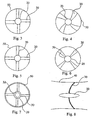
- Figure 3 is an elevation view of a rotor disk 50 having straight blades 30 of constant chord dimension, or length from the root to the tip.
- the blades 30 are arranged with the quarter chord aligned with the hub 20 axis. All blades 30 are symmetric hydrofoils in cross section.
- the blades 30 may be from two to n in plurality.
- Figure 4 is an elevation view of a rotor disk 50 having curved blades 30 narrow at the hub and wide at the tips.
- curved blades 30 wide at the hub 20 having narrow tips may be used (not shown).
- All blades 30 are symmetric hydrofoils in cross section. The direction of sweep of the blades 30 is aft or towards the center of the turbine generator unit hub 20, but a forward sweep is also an option.
- the blades 30 may be from two to n in plurality.
- Figure 5 is an elevation view of a turbine rotor disk 50, blade 30 and rotor rim 54 with straight blades 30 of constant chord dimension with the centerline aligned with the hub 20 axis.
- the blades 30 may be from two to n in plurality.
- Figure 6 is an elevation view of a rotor disk 50 having straight blades 30 narrow at the hub 20 and wide at the tips.
- straight blades 30 wide at the hub 20 having narrow tips may be used (not shown).
- All blades 30 are symmetric hydrofoils in cross section.
- the blades 30 may be from two to n in plurality.
- FIG 7 is an elevation view of a rotor disk 50, blade 30 and rotor rim 54 (see Figure I) with perpendicular offset blades and a sea life bypass 32.
- the sea life bypass 32 is a longitudinal hole through the central axis of the hub 20 through which sea life such as fish and mammals can pass if they enter into the turbine generator unit 10.
- the bypass 32 is possible due to the rim generation style of the turbine generator unit 10, leaving the hub 20 as a small structural member used only as a rotor disk 50 bearing shaft and not housing the generator 90.
- Figure 8 is a section view of a turbine rotor-disk arrangement with a curved surface for the rotor disk 50 instead of a flat plane.
- This arrangement may be used with blades 30 of constant thickness of variable thickness.
- This arrangement may be used with single or multiple rotor disks and with any arrangement of rotor blades 30 from the previous figures.
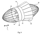
- FIG 9 is an isometric view of the preferred embodiment of the invention.
- the turbine generator unit 10 may be encapsulated by a generally elliptical screen 70 attached to the duct ends 40.
- the screens 70 may consist of a plurality of bars extending longitudinally from the duct 40 and converging at points in front of, above, aside or below the two hub 20 ends.
- the screen 70 acts to minimize ingress by marine creatures and as a shield against seaweed, debris and ocean life entering the turbine generator unit 10 which may otherwise clog or damage the turbine blades 30, and guide vanes 24. Due to the shape of the screen and the tide and water flow 100 changing direction, the screens 70 are self-cleaning.
- An augmenter skirt 74 comprised of articulating panels 36 which have hinges 27 (not shown) about the longitudinal midplane of the circumference of the turbine generator unit 10.
- the screen 70 when employed in combination with a sea life bypass 32, ends at the outer rim of the bypass 32 mouth and extends to the leading edge of the duct 40, such that while debris is caught in the screen 70, sea life can pass through the turbine generator unit thereby lessening the environmental impact of the power generation.
- the turbine assembly consisting of the rotor disk 50 (and 52 if applicable) (not shown here) and generator may be inserted and removed as a unit for ease of maintenance, leaving the duct 40 and deployment means in place.
- the rotor disk SO and generator 90 (not shown here) may be a self contained core unit with a lug or hook on the top surface.
- a duct rim spacer 44 being a flexible central portion of the duct 40 is provided to enable removal of the turbine assembly. Upon removing the duct rim spacer 44 the turbine assembly 48 may be raised to the surface for servicing or replacement.
- Figure 10 shows a duct 40, with a flexible augmenter skirt 74, which is attached at the midpoint of the turbine generator 10.
- the skirt 74 comprised of a durable flexible material such a SpectraTM weave fiber is formed such that the dynamic pressure of the flow 100 will force the skirt 74 to the appropriate location with the flared end of the skirt 74 at the exit of the duct 40.
- the skirt 74 may have stiffening rings (not shown) embedded in it, but will certainly have a stiff skirt ring 75, at its largest and distal diameter, to hold the proper shape while subjected to the large dynamic pressures of the tidal flow 100.
- the skirt 74 can be comprised of durable composite material such as a 'spectra weave', or metallic articulated components.
- the skirt 74 has a larger circumference at the trailing edge such that it flares out from the duct 40.
- the skirt 74 creates a low-pressure area at the outlet of the turbine generator unit 10, which minimizes turbine efficiency losses due to the Betz effect.
- Fixed augmenters of this type cause the flow through the turbine to be increased, and are well characterized by those familiar in the art.
- Both flexible fabric and articulated metal skirts 74 are moved backwards and forwards by the dynamic force of the tidal current, when the tide changes direction, so that the skirts 74 always extend out backwards at or over the duct 40 outlet.
- This is a bi-directional, singly located, augmenter skirt 74 that is hinged, or affixed about the mid-portion of the turbine duct 40 circumference.
- the skirt may be installed about the entire circumference, or for just portions of the circumference, as desired by the specific installation, or the plurality of the units.
- Figure 11 shows a duct 40, with an articulated augmenter skirt 74, which is attached by hinges 37 at the midpoint of the turbine unit 10.
- the skirt 74 is comprised of durable and stiff panels and is positioned by the dynamic pressure of the flow 100 that will force the skirt 74 to the appropriate location with the flared end of the skirt segments at the exit of the duct 40.
- the turbine generator units 10 are comprised of duct 40 structure and materials that provide buoyancy beneficial for deployment and maintenance operations.
- the turbine generator unit is constructed of durable corrosion resistant materials.
- marine grade concrete containing lightweight internally stiffened aggregate in sufficient proportion that the whole structure is positively buoyant is used for the duct 40 and a corrosion resistant high strength material is used for the rotors 50, and shaft 19 which comprise the turbine 10 and other principal components.
- Materials such as advanced composites, concrete and steel may be used.
- the turbine generator unit 10 is coated with a silicon glass product as is known in the art to reduce hydraulic losses and to minimize fouling by attachment of marine creatures.
- the duct 40 is coated with a new silicon glass product and is preferably formed from lightweight buoyant concrete enabling the turbine generator unit 10 to be towed to the site for deployment, then moored such that the turbine generator unit 10 floats at a predetermined depth below the surface of the water 16.
- the turbine generator unit 10 is lowered into a river or sub-sea location as desired.
- the turbine generator unit uses tidal forces to generate power.
- Figure 12 is a vector diagram of airflow across a prior art symmetrical foil
- Wells in United States Patent 4,221,538 diagrams the driving vector across the hydrofoil section of the blade 30
- V is the relative velocity of the flow opposite the direction of the blade 30
- I1 and I2 are the resultant fluid vector incident velocities
- U1 and U2 represent bi-directional water flow 100
- L1 and L2 represent the normal component of lift.
- the lift across the hydrofoil blade 30 accelerates the rotor 50 in an efficient and powerful manner.
- Figure 13 is a flow diagram across two hydraulic counter-rotating blade 30 sections as components of a turbine generator unit with dual coaxial rotor disks 50. This prior art system is effective to reduce downstream losses in energy due to swirl and increase operating efficiencies over a greater velocity spectrum.
- Figure 14 is a flow diagram across a cascading pair of coaxial rotor 50 turbine generator units.
- the use of multiple cascades minimizes the pressure drops across multiple units for regimes of very high velocity.
- the number of cascading pairs of counter-rotating disks is two to n in plurality.
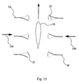
- Figure 15 is a flow diagram across a single rotor disk 50 with hydrofoil blade 30 section and through alternating position inlet and outlet guide vanes 24 .
- the vanes 24 are flexible and controlled by a linkage with the articulated skirt.
- the dynamic pressure of the flow 100 causes the skirt to adjust, thereby moving the guide vanes to the appropriate position.
- the upstream guide vanes will provide a positive angle of attack and the downstream guide vanes will reduce momentum swirl losses
- the vane 24 leading edges 28 are rigidly fixed to the hub 20 structure and the interior surface of the duct 40.
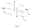
- Figure 16 is a flow diagram across two hydraulic counter-rotating blade 30 sections and through inlet and outlet guide vanes 24 as components of a dual inline rotor 50 turbine generator unit.
- the guide vanes 24 are permanently fixed in the configuration shown.
- FIG 17 is an isometric view of a hydraulic turbine generator unit 10 mounted on a telescopic pylon 80.
- the turbine generator unit 10 is mounted on a pylon 80 which may be telescopic to enable remote height adjustments of the turbine generator unit 10, including raising the turbine generator unit 10 above the surface of the water 16 for maintenance purposes.
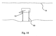
- Figure 18 is an elevation view of a turbine generator unit mounted on a plurality of telescoping pylons 80 underwater in a river or tidal stream. Installation, removal and servicing are facilitated by raising or lowering the telescoping pylons 80 to access the turbine generator unit.
- Dual coaxial rotor disks 50 and 52 may be used, as well as additional turbine generator units 10 on the same pylon 80 set. Any known cable system to remove power and to control the turbines turbine generator unit 10 may be used.
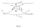
- Figure 19 is a side elevation view of a turbine generator unit 10 tethered via external lugs 12 and cables 13 to a set of two or more anchors 14 on the ocean or riverbed 15.
- the anchors may be of any type including galvanized steel ship anchors or concrete blocks.
- the cables 13 are attached to each end of the turbine generator unit 10, which is thereby held in place. As the rotors 50 and 52 are hi-directional, the turbine generator unit may remain fixed in place.
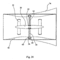
- Figure 20 is a sectional view of Figure 19 along 1-1 of a single rotor 50 turbine generator.
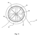
- Figure 21 is section view of Figure 19 along II-II of a single turbine generator unit.
- the turbine generator unit 10 may be deployed individually or in groups of two or more turbine generator units 10.
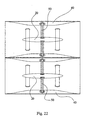
- Figure 22 is a sectional view of Figure 19 along I-I, being a dual side-by-side turbine generator unit 10 variation of the invention.
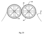
- Figure 23 is an end view of Figure 19 of the dual side-by-side turbine generator unit 10 variation.
- the duets 40 of the two turbine generator units 10 may be welded, bolted or attached together by any other means suitable to resist hydrodynamie forces.
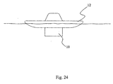
- Figure 24 is a side elevation view of a turbine generator unit 10 mounted under a barge 120 according to the invention.
- Figure 25 is a plan view of a turbine generator unit 10 mounted in a small dam 130 according to the invention.
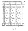
- Figure 26 is an elevation view of a complete tidal fence 140 showing several rows of turbine generator units 10 according to the invention
- Figure 27 is an close-up elevation view of a portion of a tidal fence 140 showing nine stacked turbine generator units 10 according to the invention.
- Figure 28 is an elevation view of a single turbine generator unit 10 in a tidal fence 140 according to the invention.
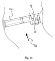
- FIG 29 is a section view showing three stacked turbine generator units 10 in the structure of a tidal fence 140.
- the tidal fence 140 according to the invention has a T-Beam structure 141, electrical and monitoring galley and associated road bed 142, the column deck structure comprised ofT-Beams 143, access cover 144, and rail lines 145 & 146, assisted by vertical support columns 147. It is additionally comprised of wave diverter 148 and removable anti-cavitation platform 149, gravity foundation structure 150, and associated support web 151, and pylons 152 & 153. This structure supports a multiplicity of turbine generator units 10.
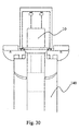
- Figure 30 is a section view of the maintenance capability for removing turbine generator units 10 in cassette form utilizing a gantry that is positioned on rails on the top of the tidal fence 140 structure.
- the preferred embodiments herein described are not intended to be exhaustive or to limit the scope of the invention to the precise forms disclosed. They are chosen and described to best explain the principles of the invention and its application and practical use to allow others skilled in the art to comprehend its teachings.
Landscapes
- Engineering & Computer Science (AREA)
- Chemical & Material Sciences (AREA)
- Combustion & Propulsion (AREA)
- Mechanical Engineering (AREA)
- General Engineering & Computer Science (AREA)
- Power Engineering (AREA)
- Oceanography (AREA)
- General Life Sciences & Earth Sciences (AREA)
- Life Sciences & Earth Sciences (AREA)
- Other Liquid Machine Or Engine Such As Wave Power Use (AREA)
- Hydraulic Turbines (AREA)
- Connection Of Motors, Electrical Generators, Mechanical Devices, And The Like (AREA)
- Transition And Organic Metals Composition Catalysts For Addition Polymerization (AREA)
- Turbine Rotor Nozzle Sealing (AREA)
- Superconductors And Manufacturing Methods Therefor (AREA)
- Earth Drilling (AREA)
Claims (41)
- Génératrice à hydroturbine (10) pour produire de l'énergie électrique à partir d'un flux d'eau (100), ledit appareil (10) comprenant un moyeu (20) essentiellement parallèle à un flux d'eau (100), au moins un disque rotor (50), et au moins une génératrice (90), caractérisé par :(a) au moins un dit disque rotor (50) comprenant une pluralité de pales hydrodynamiques (30) attachées de manière rotative audit moyeu (20) et s'étendant radialement depuis ledit moyeu (20) ;(b) une enveloppe généralement cylindrique définissant un conduit (40), ledit conduit (40) étant à proximité immédiate des extrémités desdites pales (30) et attaché audit moyeu (20) par une pluralité d'aubes directrices (24) s'étendant radialement depuis ledit moyeu (20).
- L'appareil (10) selon la revendication 1, dans lequel lesdites pales (30) ont une coupe transversale symétrique.
- L'appareil (10) selon la revendication 2, dans lequel lesdites pales (30) ont deux faces plates qui sont disposées perpendiculairement audit flux d'eau (100).
- L'appareil (10) selon l'une quelconque des revendications précédentes, dans lequel il y a un premier disque rotor (50) et un deuxième disque rotor (52), ledit premier disque rotor (50) étant en amont et tournant dans une première direction par rapport au flux d'eau (100) et ledit deuxième disque rotor (52) étant en aval et tournant en sens contraire par rapport audit premier disque rotor (50) dans une deuxième direction par rapport au flux d'eau (100).
- L'appareil (10) selon la revendication 4, dans lequel ladite première direction est en sens inverse des aiguilles d'une montre par rapport à la direction du flux d'eau (100), et ladite deuxième direction est dans le sens des aiguilles d'une montre par rapport à ladite direction du flux d'eau (100).
- L'appareil (10) selon la revendication 4, dans lequel ladite première direction est dans le sens des aiguilles d'une montre par rapport à la direction du flux d'eau (100), et ladite deuxième direction est en sens inverse des aiguilles d'une montre par rapport à ladite direction du flux d'eau (100).
- L'appareil (10) selon l'une quelconque des revendications 4 à 6, dans lequel, lorsque ledit flux d'eau (100) change de direction, ledit deuxième disque rotor (52) devient le disque en amont (52) et continue de tourner dans la même direction, tandis que le premier disque rotor (50) devient le disque en aval (50) et continue de tourner en sens contraire par rapport au disque en amont (52) dans la même direction.
- L'appareil (10) selon l'une quelconque des revendications précédentes, dans lequel lesdites aubes directrices (24) sont disposées à une extrémité ou aux deux extrémités dudit moyeu (20).
- L'appareil (10) selon l'une quelconque des revendications précédentes, dans lequel lesdites aubes directrices (24) sont courbes et essentiellement rectangulaires et s'étendent radialement depuis ledit moyeu (20) entre ledit moyeu (20) et la paroi intérieure dudit conduit (40) de sorte que ladite courbe change la direction dudit flux d'eau (100) de façon à ce qu'il heurte lesdites pales hydrodynamiques (30) à un angle aigu de façon à créer une portance et, par conséquent, une rotation desdits disques rotors (50).
- L'appareil (10) selon l'une quelconque des revendications précédentes, dans lequel lesdites aubes (24) sont fixées en position.
- L'appareil (10) selon l'une quelconque des revendications précédentes, dans lequel lesdites aubes (24) sont réglables.
- L'appareil (10) selon l'une quelconque des revendications 8 à 11, dans lequel lesdites aubes directrices (24) sont réglables de manière rotative par rapport audit moyeu (20) et audit conduit (40).
- L'appareil (10) selon la revendication 7, dans lequel, lorsque ledit flux d'eau (100) change de direction, lesdites aubes directrices (24) tournent de façon à ce que la courbe desdites aubes directrices (24) soit inversée, dirigeant ainsi ledit flux d'eau (100) à un angle préféré.
- L'appareil (10) selon la revendication 7, dans lequel, lorsque ledit flux d'eau (100) change de direction, lesdites aubes directrices courbes (24) tournent de sorte que lesdites aubes dirigeant ledit flux d'eau sur ledit disque rotor en amont (52) sont inversées. dirigeant ainsi ledit flux d'eau hors du nouveau disque rotor en aval (50) parallèlement à l'axe dudit moyeu, et lesdites aubes (24) disposées à l'extrémité en aval dudit moyeu (20) dirigeant ledit flux d'eau (100) hors de ladite turbogénératrice (10) sont alors inversées dans une position afin de diriger ledit flux d'eau (100) à un angle aigu sur ledit disque rotor antérieurement en aval (52).
- L'appareil (10) selon les revendications 12, 13 ou 14, dans lequel lesdites aubes (24) sont tournées au moyen d'un accouplement mécanique à une jupe (74) qui se retourne d'une extrémité dudit conduit (20) à l'autre tandis que ledit flux d'eau (100) change de direction.
- L'appareil (10) selon l'une quelconque des revendications précédentes, dans lequel ladite génératrice (90) est une génératrice à rotor périphérique (90).
- L'appareil (10) selon la revendication 16, dans lequel ladite génératrice (90) est constituée d'aimants (56) disposés aux extrémités desdites pales (30) et de solénoïdes disposés dans la paroi intérieure dudit conduit (20).
- L'appareil (10) selon la revendication 16 ou 17, dans lequel ladite génératrice (90) est constituée d'aimants permanents (56) dans un pourtour dudit disque rotor (50) et les bobines du stator sont disposées dans la paroi intérieure dudit conduit (20).
- L'appareil (10) selon l'une quelconque des revendications précédentes, dans lequel ladite génératrice (90) est une d'une génératrice à double ou simple flux axial (90) ou d'une génératrice à double ou simple flux radial (90).
- L'appareil (10) selon l'une quelconque des revendications précédentes, dans lequel ladite génératrice (90) est submergée d'eau ambiante.
- L'appareil (10) selon l'une quelconque des revendications précédentes, dans lequel les disques rotors (50) et les génératrices (90) sont adaptés pour être déposés comme une unité modulaire, de sorte que l'entretien et le remplacement sont grandement facilités.
- L'appareil (10) selon l'une quelconque des revendications précédentes, comprenant également une jupe réversible (74) disposée autour de la ligne médiane de la surface extérieure dudit conduit (20) et s'étendant au-delà d'une extrémité ouverte dudit conduit (20) dans la direction dudit flux d'eau (100).
- L'appareil (10) selon la revendication 22, dans lequel ladite jupe (74) est adaptée pour se soulever et se retourner lorsque ledit flux d'eau (100) s'inverse de telle sorte que ladite jupe (74) sera toujours étendue depuis ladite ligne médiane dudit conduit (40) vers l'extrémité en aval de ladite hydroturbine (48).
- L'appareil (10) selon la revendication 22 ou 23, dans lequel ladite jupe (74) est constituée en un matériau flexible.
- L'appareil (10) selon l'une quelconque des revendications 22 à 24, dans lequel ladite jupe (74) est constituée de panneaux articulés.
- L'appareil (10) selon l'une quelconque des revendications précédentes, comprenant également un écran (70) disposé autour des extrémités ouvertes dudit conduit (40) de façon à ce que les débris et les créatures vivantes soient déviées par ledit écran (70).
- L'appareil (10) selon la revendication 26, dans lequel ledit écran (70) consiste en des barres métalliques.
- L'appareil (10) selon la revendication 26 ou 27, dans lequel lesdites barres s'étendent vers l'avant depuis les extrémités dudit conduit (40) jusqu'à un point en avant du centre des extrémités dudit conduit (40).
- L'appareil (10) selon l'une quelconque des revendications 26 à 28, dans lequel ledit écran (70) consiste en des lattes orientées tangentiellement audit flux d'eau (100) de façon à ce que les débris et les créatures vivantes soient déviées autour de ladite turbine (48).
- L'appareil (10) selon l'une quelconque des revendications précédentes, comprenant également un trou de dérivation (32) défini par ledit moyeu (20) de façon à ce que ledit flux d'eau (100) passe longitudinalement à travers ledit moyeu (20).
- Un appareil (10) selon l'une quelconque des revendications précédentes, dans lequel au moins une turbogénératrice (10) est montée sur au moins un pylône sous-marin télescopique (152) adapté de façon à abaisser ou élever sélectivement ladite turbogéntrattice (10) au-dessus d'une surface d'eau et aux profondeurs sous-marines sélectionnées de façon à ce que la production d'énergie soit optimisée.
- L'appareil (10) selon l'une quelconque des revendications précédentes, dans lequel ladite génératrice à hydroturbine (10) est bidirectionnelle et peut accepter ledit flux d'eau (100) depuis l'une ou l'autre des deux extrémités ouvertes et produire de l'énergie.
- L'appareil (10) selon l'une quelconque des revendications précédentes, dans lequel ledit conduit (40) a une surface interne convergente telle qu'un effet Venturi est créé.
- L'appareil (10) selon l'une quelconque des revendications précédentes, dans lequel lesdits disques rotors (50) sont coaxiaux et tournent en sens contraire.
- L'appareil (10) selon la revendication 33 ou 34, dans lequel il y a 2 à 10 paires en cascade de turbogénératrices coaxiales tournant en sens contraire (10).
- Un appareil (10) pour une turbine à fluide comprenant un arbre (20) et une pluralité de pales rotatives (30) et caractérisé par :(a) lesdites pales rotatives (30) s'étendant radialement depuis ledit arbre (20) ; et(b) une pluralité d'aubes directrices réglables (24) s'étendant radialement depuis ledit arbre (20) à la fois à une extrémité en aval et à une extrémité en amont de ladite turbine (10).
- L'appareil (10) selon la revendication 36, comprenant également un conduit (40) disposé autour desdites pales (30) de façon à ce que les extrémités desdites pales (30) soient proximales audit conduit (40).
- L'appareil (10) selon la revendication 35 ou 36, comprenant un moyen de production d'énergie à rotor périphérique (90).
- L'appareil (10) selon l'une quelconque des revendications 36 à 38, dans lequel ledit arbre (20) est creux, permettant ainsi à la vie marine d'éviter la turbine à fluide.
- Dans une hydroturbine (10), avec un moyeu (20) et une enveloppe (40), pour produire de l'énergie électrique à partir d'un courant de marée, une amélioration caractérisée par :(a) une pluralité de pales hydrodynamiques symétriques (30) disposées radialement et de manière rotative autour dudit moyeu (20) ; et(b) ladite enveloppe (40) étant disposée autour desdites pales (30) et attachée audit moyeu (20) par au moins un support de moyeu (22), ladite enveloppe (40) comprenant un moyen de flottabilité intégré audit moyeu (20) de sorte que ladite turbogénératrice (10) flotte à une profondeur sous-marine prédéterminée.
- L'hydroturbine (10) de la revendication 40, dans laquelle ledit moyeu (20) comprend un trou (32) dans ledit moyeu (20) qui s'étend à travers ledit moyeu (20).
Priority Applications (1)
| Application Number | Priority Date | Filing Date | Title |
|---|---|---|---|
| DK02762175T DK1430220T3 (da) | 2001-09-17 | 2002-09-16 | Undervandsrörturbine |
Applications Claiming Priority (3)
| Application Number | Priority Date | Filing Date | Title |
|---|---|---|---|
| US32244301P | 2001-09-17 | 2001-09-17 | |
| US322443P | 2001-09-17 | ||
| PCT/CA2002/001413 WO2003025385A2 (fr) | 2001-09-17 | 2002-09-16 | Groupe turbine a eau |
Publications (2)
| Publication Number | Publication Date |
|---|---|
| EP1430220A2 EP1430220A2 (fr) | 2004-06-23 |
| EP1430220B1 true EP1430220B1 (fr) | 2005-06-15 |
Family
ID=23254911
Family Applications (1)
| Application Number | Title | Priority Date | Filing Date |
|---|---|---|---|
| EP02762175A Expired - Lifetime EP1430220B1 (fr) | 2001-09-17 | 2002-09-16 | Groupe turbine a eau |
Country Status (13)
| Country | Link |
|---|---|
| US (3) | US7471009B2 (fr) |
| EP (1) | EP1430220B1 (fr) |
| JP (1) | JP4024208B2 (fr) |
| KR (1) | KR101033544B1 (fr) |
| CN (1) | CN1636111B (fr) |
| AT (1) | ATE298042T1 (fr) |
| AU (1) | AU2002328217B2 (fr) |
| CA (1) | CA2460479C (fr) |
| DE (1) | DE60204707T2 (fr) |
| ES (1) | ES2243756T3 (fr) |
| NO (2) | NO328222B1 (fr) |
| PT (1) | PT1430220E (fr) |
| WO (1) | WO2003025385A2 (fr) |
Cited By (5)
| Publication number | Priority date | Publication date | Assignee | Title |
|---|---|---|---|---|
| DE102009018758A1 (de) | 2009-04-27 | 2010-10-28 | Voith Patent Gmbh | Unterwasserkraftwerk mit einer bidirektional anströmbaren, gleichsinnig umlaufenden Wasserturbine |
| CN103114960A (zh) * | 2013-02-05 | 2013-05-22 | 厦门大学 | 可用于低速环境的潮流能发电装置 |
| WO2013128451A1 (fr) * | 2012-03-01 | 2013-09-06 | Ofer Birarov | Eolienne |
| US9000604B2 (en) | 2010-04-30 | 2015-04-07 | Clean Current Limited Partnership | Unidirectional hydro turbine with enhanced duct, blades and generator |
| CN103206332B (zh) * | 2013-04-01 | 2015-08-12 | 武汉理工大学 | 一种贯流式水轮机自动清洁装置 |
Families Citing this family (331)
| Publication number | Priority date | Publication date | Assignee | Title |
|---|---|---|---|---|
| IL152090A0 (en) * | 2002-10-03 | 2003-05-29 | Kobi Miller | Mechanism for rotating the rotors and stators of electric power generators |
| NO321755B1 (no) * | 2003-06-25 | 2006-07-03 | Sinvent As | Fremgangsmate og anordning for omforming av energi fra/til vann under trykk. |
| US20050005592A1 (en) * | 2003-07-07 | 2005-01-13 | Fielder William Sheridan | Hollow turbine |
| USD531957S1 (en) * | 2003-10-09 | 2006-11-14 | Access Business Group International Llc | Generator |
| GB0328732D0 (en) * | 2003-12-11 | 2004-01-14 | Uws Ventures Ltd | Water turbine |
| SE526789C2 (sv) * | 2004-03-16 | 2005-11-08 | Uppsala Power Man Consultants | Aggregat innefattande en vattenturbin och en generator, vars rotor är direktförbunden med vardera av turbinens blad |
| US7258523B2 (en) * | 2004-05-25 | 2007-08-21 | Openhydro Group Limited | Means to regulate water velocity through a hydro electric turbine |
| DE102004037985A1 (de) * | 2004-08-05 | 2006-03-16 | Voith Siemens Hydro Power Generation Gmbh & Co. Kg | Hydraulische Turbine oder Pumpturbine |
| NO323923B1 (no) * | 2004-08-25 | 2007-07-23 | Norpropeller As | Elektrisk generator og turbin-generator-aggregat |
| US7235894B2 (en) * | 2004-09-01 | 2007-06-26 | Roos Paul W | Integrated fluid power conversion system |
| CA2481820C (fr) | 2004-09-17 | 2009-09-01 | Clean Current Power Systems Incorporated | Augmentation de debit pour turbogeneratrice sous-marine |
| WO2006047739A2 (fr) * | 2004-10-27 | 2006-05-04 | Murphy Michael A | Dispositif utilisant de l'eau pour appliquer un couple sur un generateur |
| EP1834087A4 (fr) * | 2004-12-17 | 2009-10-21 | Composite Support & Solutions | Eolienne a accroissement de diffusion |
| FR2880389B1 (fr) * | 2005-01-05 | 2007-04-20 | Electricite De France | Structure de connexion pour une unite de production d'electricite immergee |
| FR2880388B1 (fr) * | 2005-01-05 | 2017-07-28 | Electricite De France Service Nat | Unite de production d'electricite immergee |
| ES2300180B1 (es) * | 2006-03-27 | 2009-02-16 | Maria Elena Novo Vidal | Sistema de generacion de energia electrica a partir de corrientes marinas y del movimiento del oleaje. |
| ES2285895B1 (es) * | 2005-04-11 | 2008-09-01 | Maria Elena Novo Vidal | Generador electrico accionado por turbina. |
| US7843099B2 (en) * | 2005-04-25 | 2010-11-30 | William Sheridan Fielder | Hollow generator |
| ITRM20050216A1 (it) * | 2005-05-05 | 2006-11-06 | Francis Allen Farrelly | Dispositivo di ugello asimmetrico con turbina idrica per lo sfruttamento dell'energia idrocinetica. |
| US7352078B2 (en) * | 2005-05-19 | 2008-04-01 | Donald Hollis Gehring | Offshore power generator with current, wave or alternative generators |
| US7215036B1 (en) * | 2005-05-19 | 2007-05-08 | Donald Hollis Gehring | Current power generator |
| DE102005032381A1 (de) * | 2005-07-08 | 2007-01-11 | Wobben, Aloys, Dipl.-Ing. | Turbine für eine Wasserkraftanlage |
| US7378750B2 (en) | 2005-07-20 | 2008-05-27 | Openhybro Group, Ltd. | Tidal flow hydroelectric turbine |
| GB0516149D0 (en) * | 2005-08-05 | 2005-09-14 | Univ Strathclyde | Turbine |
| GB0600942D0 (en) * | 2006-01-18 | 2006-02-22 | Marine Current Turbines Ltd | Improvements in gravity foundations for tidal stream turbines |
| DE102006003799B4 (de) * | 2006-01-25 | 2010-05-06 | Daimler Ag | Brennstoffzellensystem mit Brennstoffzelle, Wasserstoffspeicher und Anodenkreislauf und dessen Verwendung |
| CN101389853A (zh) * | 2006-03-21 | 2009-03-18 | 国际壳牌研究有限公司 | 涡轮组件和发电机 |
| FR2898941A1 (fr) * | 2006-03-25 | 2007-09-28 | Max Sardou | Energie renouvelable l'hydrolienne flottante |
| CA2544108C (fr) | 2006-04-19 | 2013-06-04 | Metin Ilbay Yaras | Turbine hydraulique a effet vortex |
| US7528497B2 (en) * | 2006-07-11 | 2009-05-05 | Hamilton Sundstrand Corporation | Wind-turbine with load-carrying skin |
| EP1878912B1 (fr) * | 2006-07-14 | 2011-12-21 | OpenHydro Group Limited | Turbines hydroélectriques submergées ayant des chambres de flotabilité |
| DE602006002883D1 (de) * | 2006-07-14 | 2008-11-06 | Openhydro Group Ltd | Turbinen mit einer Rutsche zum Durchfluss von Fremdkörpern |
| EP1879280B1 (fr) * | 2006-07-14 | 2014-03-05 | OpenHydro Group Limited | Turbine hydroélectrique |
| EP1878913B1 (fr) * | 2006-07-14 | 2013-03-13 | OpenHydro Group Limited | Turbine maremotrice bidirectionnelle |
| US20080018115A1 (en) * | 2006-07-20 | 2008-01-24 | Boray Technologies, Inc. | Semi-submersible hydroelectric power plant |
| DE102006043946A1 (de) * | 2006-09-14 | 2008-03-27 | Oswald Elektromotoren Gmbh | Turbinenvorrichtung |
| US20110049894A1 (en) * | 2006-10-06 | 2011-03-03 | Green William M | Electricity Generating Assembly |
| NZ576969A (en) * | 2006-10-13 | 2013-03-28 | Stephen Mark West | Turbine unit with first and second blade sets being rotated in same direction and set in reverse so that a region between is at a lower pressure than inlet passage of unit |
| RU2321939C1 (ru) * | 2006-10-16 | 2008-04-10 | Юлия Алексеевна Щепочкина | Винт |
| US7710081B2 (en) | 2006-10-27 | 2010-05-04 | Direct Drive Systems, Inc. | Electromechanical energy conversion systems |
| GB0621381D0 (en) * | 2006-10-27 | 2006-12-06 | Neptune Renewable Energy Ltd | Tidal power apparatus |
| US7603864B2 (en) * | 2006-11-29 | 2009-10-20 | General Electric Company | Blade tip electric machine |
| GB0700128D0 (en) * | 2007-01-04 | 2007-02-14 | Power Ltd C | Tidal electricity generating apparatus |
| GB0704897D0 (en) * | 2007-03-14 | 2007-04-18 | Rotech Holdings Ltd | Power generator and turbine unit |
| US8376686B2 (en) | 2007-03-23 | 2013-02-19 | Flodesign Wind Turbine Corp. | Water turbines with mixers and ejectors |
| US8622688B2 (en) | 2007-03-23 | 2014-01-07 | Flodesign Wind Turbine Corp. | Fluid turbine |
| US8123457B2 (en) * | 2007-03-27 | 2012-02-28 | Hydro Green Energy, Llc | System and apparatus for improved turbine pressure and pressure drop control using turbine head potential |
| EP1980746B2 (fr) * | 2007-04-11 | 2013-08-07 | OpenHydro Group Limited | Procédé d'installation d'une turbine hydroélectrique |
| EP1980670B1 (fr) * | 2007-04-11 | 2009-07-15 | OpenHydro Group Limited | Procédé pour le déploiement d'une turbine hydroélectrique |
| WO2008134868A1 (fr) * | 2007-05-05 | 2008-11-13 | Gordon David Sherrer | Système et procédé permettant d'extraire de l'énergie d'un fluide |
| GB0710822D0 (en) * | 2007-06-05 | 2007-07-18 | Overberg Ltd | Mooring system for tidal stream and ocean current turbines |
| US8049351B2 (en) * | 2007-06-15 | 2011-11-01 | E-Net, Llc | Turbine energy generating system |
| WO2010020018A1 (fr) * | 2008-08-22 | 2010-02-25 | Fourivers Power Engineering Pty Ltd | Appareil de production d'énergie |
| WO2009026620A1 (fr) * | 2007-08-24 | 2009-03-05 | Fourivers Power Engineering Pty Ltd | Appareil de génération d'énergie marine utilisant les courants océaniques |
| US7928595B1 (en) | 2007-09-19 | 2011-04-19 | Julio Gonzalez-Carlo | Electric power generation system for harvesting underwater currents |
| US8575775B1 (en) | 2007-09-19 | 2013-11-05 | Julio Gonzalez-Carlo | Electrical power generation system for harvesting underwater currents |
| US20100148515A1 (en) * | 2007-11-02 | 2010-06-17 | Mary Geddry | Direct Current Brushless Machine and Wind Turbine System |
| KR101164344B1 (ko) * | 2007-11-15 | 2012-07-09 | 고쿠리쓰다이가쿠호진 규슈다이가쿠 | 비정상류를 이용한 유체기계, 풍력 터빈, 및 유체기계의 내부 유속 증가 방법 |
| GB2469760B (en) * | 2007-11-16 | 2013-03-20 | Elemental Energy Technologies Ltd | A power generator |
| KR101489218B1 (ko) * | 2007-11-16 | 2015-02-04 | 엘리멘털 에너지 테크널러지스 리미티드 | 동력발생장치 조립체, 발전장치 설비 및 추진 또는 펌프장치 |
| JP2011504559A (ja) | 2007-11-23 | 2011-02-10 | アトランティス リソーセズ コーポレーション ピーティーイー リミテッド | 水流からエネルギーを抽出するための制御システム |
| US7586207B2 (en) * | 2007-12-05 | 2009-09-08 | Kinetic Wave Power | Water wave power system |
| US20090146430A1 (en) * | 2007-12-10 | 2009-06-11 | Walter Edmond Sear | Tidal/water current electrical generating system |
| ATE480035T1 (de) * | 2007-12-12 | 2010-09-15 | Openhydro Group Ltd | Generatorkomponente für eine hydroelektrische turbine |
| DE202007017544U1 (de) * | 2007-12-13 | 2009-04-23 | Schiller, Helmut | Unterwasser Turbine |
| US7928594B2 (en) * | 2007-12-14 | 2011-04-19 | Vladimir Anatol Shreider | Apparatus for receiving and transferring kinetic energy from a flow and wave |
| EP2232054A4 (fr) * | 2007-12-20 | 2012-11-21 | Rsw Rer Ltd | Turbine à récupération d'énergie cinétique |
| FR2925621B1 (fr) * | 2007-12-21 | 2018-01-26 | Dcns | Dispositif electrohydraulique de generation d'electricite et utilisation |
| JP5522406B2 (ja) * | 2008-01-08 | 2014-06-18 | レイノルズ,リチャード,アーサー,ヘンリー | タービン組立体 |
| NL2001190C1 (nl) * | 2008-01-16 | 2009-07-20 | Lagerwey Wind B V | Generator voor een direct aangedreven windturbine. |
| NL1034952C2 (nl) * | 2008-01-25 | 2009-07-30 | Antonie Ten Bosch | Een vaarbare getijdenstroom turbinemuur energiecentrale. |
| DE102008007043A1 (de) * | 2008-01-31 | 2009-08-06 | Voith Patent Gmbh | Freistehende, tauchende Energieerzeugungsanlage mit einer Axialturbine |
| DE102008007616A1 (de) * | 2008-02-04 | 2009-08-06 | Universität Siegen | Rotorblattgestaltung für eine Wellsturbine |
| EP2088311B1 (fr) * | 2008-02-05 | 2015-10-14 | OpenHydro Group Limited | Turbine hydroélectrique avec rotor flottant |
| US8759997B2 (en) * | 2008-02-19 | 2014-06-24 | Jeffrey Ryan Gilbert | Energy recovery system for exhaust energy capture and electrical generation with generator built into fan |
| US20100283248A1 (en) | 2009-02-20 | 2010-11-11 | Moffat Brian L | Venturi based ocean wave energy conversion system |
| US8925313B2 (en) | 2008-02-22 | 2015-01-06 | Brian Lee Moffat | Wave energy conversion apparatus |
| RU2362043C1 (ru) * | 2008-03-28 | 2009-07-20 | Виктор Михайлович Лятхер | Энергетический агрегат |
| US20090250937A1 (en) * | 2008-04-07 | 2009-10-08 | Stuart Manuel I | Relative wind vortex rotary turbine alternating current device (RWVT) |
| US20090257863A1 (en) * | 2008-04-11 | 2009-10-15 | Asia Power Dev. Foundation, Inc. | Turbine assembly |
| AU2009238205B2 (en) * | 2008-04-14 | 2014-06-05 | Atlantis Resources Corporation Pte Limited | Central axis water turbine |
| CN102066744B (zh) * | 2008-04-14 | 2014-07-23 | 亚特兰蒂斯能源有限公司 | 海底涡轮机叶片 |
| WO2009129309A2 (fr) * | 2008-04-15 | 2009-10-22 | Sonic Blue Aerospace, Inc. | Aérogénérateurs annulaires supraconducteurs à turbine |
| AU2009236140B2 (en) * | 2008-04-16 | 2013-03-21 | Flodesign Wind Turbine Corp. | Water turbines with mixers and ejectors |
| EP2110910A1 (fr) * | 2008-04-17 | 2009-10-21 | OpenHydro Group Limited | Procédé amélioré d'installation de turbine |
| EP2112370B1 (fr) * | 2008-04-22 | 2016-08-31 | OpenHydro Group Limited | Turbine hydroélectrique disposant d'un palier magnétique |
| RS20080196A (en) * | 2008-05-08 | 2011-02-28 | PAUNOVIĆ, Nenad | PIPE TURBINE WITH ROLE OF ELECTROGENERATOR AND DRIVE PROPELLER |
| RU2453725C2 (ru) * | 2008-05-26 | 2012-06-20 | Аратек Энженариа Консульториа Э Репрезентасойнс Лтда. | Электрогенерирующее устройство |
| WO2009153124A2 (fr) | 2008-05-27 | 2009-12-23 | Siemens Aktiengesellschaft | Turbomachine pourvue de deux rotors |
| ES2354799B1 (es) * | 2008-06-09 | 2012-01-25 | Sebastián Enrique Bendito Vallori | Sistema de amortiguación neumática subacuática transformadora de las energías cinética y potencial propias de la mar. |
| DE102008032411A1 (de) * | 2008-07-10 | 2010-01-14 | INSTI-EV-Sachsen e.V. c/o IREG mbH | Strömungswandler |
| US20110109090A1 (en) | 2009-11-09 | 2011-05-12 | Bolin William D | Fin-Ring Propeller For A Water Current Power Generation System |
| US8253298B2 (en) | 2008-07-28 | 2012-08-28 | Direct Drive Systems, Inc. | Slot configuration of an electric machine |
| GB2462257B (en) | 2008-07-29 | 2010-09-29 | Clean Current Power Systems | Electrical machine with dual insulated coil assembly |
| ES2351826B1 (es) * | 2008-07-30 | 2011-12-01 | Pablo Gonzalez Alvarez | Sistema de aprovechamiento energético para canales de agua. |
| AU2012216624B2 (en) * | 2008-08-22 | 2014-04-17 | 4Rivers Power Engineering Pty Ltd | Power Generation Apparatus |
| AU2009287351B2 (en) * | 2008-09-01 | 2015-01-22 | Wave Power Renewables Limited | Improvements in ocean wave energy extraction |
| US8338974B2 (en) * | 2008-09-12 | 2012-12-25 | AGlobal Tech, LLC | Wind turbine |
| GB2463504B (en) * | 2008-09-16 | 2011-02-16 | Verderg Ltd | Method and apparatus for installing tidal barrages |
| GB0818825D0 (en) * | 2008-10-14 | 2008-11-19 | Evans Michael J | Water turbine utilising axial vortical flow |
| CN102224338B (zh) * | 2008-10-29 | 2015-07-01 | 因文图公司 | 旋转设备 |
| WO2010062788A2 (fr) * | 2008-11-03 | 2010-06-03 | Mary Geddry | Machine à courant continu sans balai et système éolien |
| DE102008054361A1 (de) * | 2008-11-03 | 2010-05-12 | Ksb Aktiengesellschaft | Energieerzeugungseinheit sowie Verfahren zur Wartung einer Energieerzeugungseinheit |
| US20110286832A1 (en) * | 2010-05-24 | 2011-11-24 | Israel Ortiz | Back to back turbine |
| US8193653B2 (en) * | 2010-05-07 | 2012-06-05 | Israel Ortiz | Automatic pitch turbine |
| CA2645296A1 (fr) * | 2008-11-27 | 2010-05-27 | Organoworld Inc. | Turbine annulaire multirotor a double paroi |
| WO2010064918A1 (fr) * | 2008-12-03 | 2010-06-10 | Prototech As | Système de conversion d'énergie |
| EP2199598B1 (fr) | 2008-12-18 | 2012-05-02 | OpenHydro IP Limited | Turbine hydroélectrique avec un frein passif et procédé d'opération |
| EP2209175B1 (fr) | 2008-12-19 | 2010-09-15 | OpenHydro IP Limited | Procédé d'installation d'un générateur de turbine hydroélectrique |
| WO2010074670A1 (fr) * | 2008-12-22 | 2010-07-01 | Anthony Branco | Turbine à fluide pour génération d'électricité |
| RS20090054A (en) * | 2009-02-06 | 2010-12-31 | Nenad PAUNOVIĆ | Housing for hydro and aero turbines |
| GB0902289D0 (en) * | 2009-02-12 | 2009-03-25 | Marine Current Turbines Ltd | Methods for installing pin-piled jacket type structures at sea |
| US20120068670A1 (en) * | 2009-03-16 | 2012-03-22 | Bersiek Shamel A | Wind jet turbine |
| US8378518B2 (en) * | 2009-03-26 | 2013-02-19 | Terra Telesis, Inc. | Wind power generator system, apparatus, and methods |
| MX2011010085A (es) * | 2009-03-26 | 2012-02-13 | Hydro Green Energy Llc | Metodo y aparato para la generacion de energia hidroelectrica mejorada en los embalses existentes. |
| CA2756446C (fr) * | 2009-03-27 | 2020-12-29 | Brian Lee Moffat | Appareil de conversion de l'energie des vagues |
| US8400006B2 (en) * | 2009-09-02 | 2013-03-19 | Blue Energy Canada Inc. | Hydrodynamic array |
| ATE548562T1 (de) | 2009-04-17 | 2012-03-15 | Openhydro Ip Ltd | Verbessertes verfahren zur steuerung der ausgabe eines hydroelektrischen turbinengenerators |
| US7825532B1 (en) * | 2009-04-20 | 2010-11-02 | Barber Gerald L | Electrical generator for wind turbine |
| US8373298B2 (en) * | 2009-04-20 | 2013-02-12 | Gerald L. Barber | Electrical generator for wind turbine |
| KR20120042746A (ko) | 2009-04-28 | 2012-05-03 | 아틀란티스 리소시스 코포레이션 피티이 리미티드 | 수중 동력 발생기 |
| US20100290900A1 (en) * | 2009-05-17 | 2010-11-18 | Wayne Krouse | Hydropower system with increased power input characteristics |
| US8178987B2 (en) * | 2009-05-20 | 2012-05-15 | E-Net, Llc | Wind turbine |
| BRPI1011172A2 (pt) * | 2009-05-20 | 2016-03-15 | E Net Llc | turbina eólica |
| US20100295305A1 (en) * | 2009-05-20 | 2010-11-25 | E-Net, Llc | Wind turbine and control system |
| US7969029B2 (en) * | 2009-06-01 | 2011-06-28 | Santiago Vitagliano | Dynamic pressure differential hydroelectric generator |
| US8461713B2 (en) * | 2009-06-22 | 2013-06-11 | Johann Quincy Sammy | Adaptive control ducted compound wind turbine |
| JP4422789B1 (ja) * | 2009-08-03 | 2010-02-24 | 日本システム企画株式会社 | 水力発電装置の設置構造 |
| US20140028028A1 (en) * | 2009-08-19 | 2014-01-30 | Clarence Edward Frye | Free-flow hydro powered turbine system |
| US8344536B1 (en) | 2009-09-01 | 2013-01-01 | Valentino Gotay | Sewer electrical generation apparatus |
| US8446032B2 (en) * | 2009-09-04 | 2013-05-21 | Chaup Inc. | Hydroelectric power generator and related methods |
| US20120267895A1 (en) * | 2009-09-08 | 2012-10-25 | Atlantis Resources Corporation Pte Limited | Power generator |
| EP2302766B1 (fr) | 2009-09-29 | 2013-03-13 | OpenHydro IP Limited | Turbine hydroélectrique avec refroidissement de bobine |
| EP2302755B1 (fr) | 2009-09-29 | 2012-11-28 | OpenHydro IP Limited | Système et procédé de conversion d'alimentation électrique |
| EP2302204A1 (fr) | 2009-09-29 | 2011-03-30 | OpenHydro IP Limited | Système de turbine hydroélectrique |
| KR101041539B1 (ko) * | 2009-09-30 | 2011-06-17 | 한국전력공사 | 유속 유량 조절형 초저낙차 수차의 구조 |
| US20110080002A1 (en) * | 2009-10-02 | 2011-04-07 | Jose Ramon Santana | Controlled momentum hydro-electric system |
| KR20120087159A (ko) | 2009-10-27 | 2012-08-06 | 아틀란티스 리소시스 코포레이션 피티이 리미티드 | 수중 동력 발생기 |
| DE102009053879A1 (de) | 2009-11-20 | 2011-05-26 | Voith Patent Gmbh | Gezeitenkraftwerk und Verfahren für dessen Erstellung |
| KR101155290B1 (ko) * | 2009-12-16 | 2012-06-13 | 한국해양연구원 | 파력발전 시스템 |
| US8063528B2 (en) * | 2009-12-18 | 2011-11-22 | General Electric Company | Counter-rotatable generator |
| US10138907B2 (en) | 2009-12-23 | 2018-11-27 | Energy Recovery, Inc. | Rotary energy recovery device |
| GB2477532B (en) * | 2010-02-05 | 2012-10-24 | Rolls Royce Plc | A bidirectional water turbine |
| EP2547898B1 (fr) | 2010-03-16 | 2022-05-04 | Verderg Ltd | Appareil de génération de puissance à partir d'un écoulement de fluide |
| DE102010018804A1 (de) | 2010-04-29 | 2011-11-03 | Voith Patent Gmbh | Wasserturbine |
| US8461730B2 (en) * | 2010-05-12 | 2013-06-11 | Science Applications International Corporation | Radial flux permanent magnet alternator with dielectric stator block |
| GB2480694B (en) * | 2010-05-28 | 2014-06-25 | Robert William Wallace Burden | Energy extraction from the ocean depths |
| US9097233B1 (en) * | 2010-06-01 | 2015-08-04 | Dennis Allen Ramsey | Suction-augmented hydropower turbine |
| CN102269096B (zh) * | 2010-06-07 | 2016-05-04 | 黄滕溢 | 水流发电系统及其设置及维修方法 |
| DE102010017343B4 (de) * | 2010-06-11 | 2014-04-10 | Dr. Ing. H.C. F. Porsche Aktiengesellschaft | Strömungsenergieanlage |
| US8814493B1 (en) * | 2010-07-02 | 2014-08-26 | William Joseph Komp | Air-channeled wind turbine for low-wind environments |
| US20120038158A1 (en) * | 2010-08-13 | 2012-02-16 | Chen Tzeng-Yuan | Wind power generating module for use with electric scooter |
| US20120070275A1 (en) * | 2010-09-16 | 2012-03-22 | Flodesign Wind Turbine Corporation | Airfoil for energy extracting shrouded fluid turbines |
| US8653682B2 (en) | 2010-09-27 | 2014-02-18 | Thomas Rooney | Offshore hydroelectric turbine assembly and method |
| US8558403B2 (en) * | 2010-09-27 | 2013-10-15 | Thomas Rooney | Single moored offshore horizontal turbine train |
| US8506244B2 (en) | 2010-09-29 | 2013-08-13 | George F. MCBRIDE | Instream hydro power generator |
| WO2012051382A1 (fr) * | 2010-10-13 | 2012-04-19 | Houvener Robert C | Dispositif et méthode de transfert d'énergie hydrocinétique |
| PT2630366T (pt) * | 2010-10-22 | 2018-11-06 | Wave Power Renewables Ltd | Unidade de rotor de turbina |
| CN103429821B (zh) | 2010-10-26 | 2015-11-25 | 加拿大蓝色能量有限公司 | 具有公共交通隧道的流体动力阵列 |
| USD640980S1 (en) * | 2010-11-05 | 2011-07-05 | Flodesign Wind Turbine Corp. | Water turbine |
| EP2450562B1 (fr) | 2010-11-09 | 2015-06-24 | Openhydro IP Limited | Système de récupération pour une turbine hydroélectrique et procédé de récupération |
| USD652794S1 (en) | 2010-11-12 | 2012-01-24 | Verterra Energy Inc. | Turbine |
| US8487468B2 (en) | 2010-11-12 | 2013-07-16 | Verterra Energy Inc. | Turbine system and method |
| CN102230442B (zh) * | 2010-12-09 | 2013-03-27 | 胡彬 | 无轴海流涡轮发电机 |
| EP2469257B1 (fr) | 2010-12-23 | 2014-02-26 | Openhydro IP Limited | Procédé de test de turbine hydroélectrique |
| WO2012100128A2 (fr) * | 2011-01-21 | 2012-07-26 | Anagnou Mars C | Système de génération de puissance hydroélectrique |
| US20140145445A1 (en) * | 2011-02-04 | 2014-05-29 | Centre Hydrolien Industriel Quebecois Inc. | Marine turbine assembly |
| AU2012219353B2 (en) * | 2011-02-18 | 2015-12-17 | Concepts Nrec, Llc | Turbomachinery having self-articulating blades, shutter valve, partial-admission shutters, and/or variable-pitch inlet nozzles |
| CA141974S (en) * | 2011-02-22 | 2012-07-23 | Guinard En Sarl | Turbine device for generating electricity from ocean currents |
| US9822757B2 (en) * | 2011-02-23 | 2017-11-21 | The Woods Hole Group, Inc. | Underwater tethered telemetry platform |
| WO2012113031A1 (fr) * | 2011-02-24 | 2012-08-30 | Portlane Technologies Pty Ltd | Appareil de production d'électricité |
| US9051918B1 (en) | 2011-02-25 | 2015-06-09 | Leidos, Inc. | Vertical axis wind turbine with tensile support structure having rigid or collapsible vanes |
| JP5479388B2 (ja) * | 2011-02-28 | 2014-04-23 | 三菱重工業株式会社 | 風車翼およびこれを備えた風力発電装置 |
| USD699676S1 (en) * | 2011-03-22 | 2014-02-18 | Vortex Wind Turbines AG | Wind turbine |
| US20120269628A1 (en) * | 2011-04-06 | 2012-10-25 | Liu Kuo-Shen | Device of Floating Wind Turbine Capable of Counterbalancing Torques Therein |
| CN103321820B (zh) * | 2011-04-18 | 2016-02-10 | 浙江海洋学院 | 多向自适应悬浮型潮流能水轮机 |
| CN102146867A (zh) * | 2011-04-18 | 2011-08-10 | 浙江海洋学院 | 多向自适应悬浮型潮流能水轮机 |
| US9322391B2 (en) | 2011-04-27 | 2016-04-26 | SkyWolf Wind Turbine Corp. | Housing for a high efficiency wind turbine |
| US8672624B2 (en) | 2011-04-27 | 2014-03-18 | SkyWolf Wind Turbine Corp. | High efficiency wind turbine having increased laminar airflow |
| US8851836B2 (en) | 2011-04-27 | 2014-10-07 | SkyWolf Wind Turbine Corp. | High efficiency wind turbine including photovoltaic cells |
| US8721279B2 (en) | 2011-04-27 | 2014-05-13 | SkyWolf Wind Turbines Corp. | Multiple mixing internal external fluid driven high efficiency wind turbine having reduced downstream pressure |
| US9133815B1 (en) | 2011-05-11 | 2015-09-15 | Leidos, Inc. | Propeller-type double helix turbine apparatus and method |
| DE102011075700A1 (de) * | 2011-05-12 | 2012-11-15 | Robert Bosch Gmbh | Offshore-System zur Erzeugung regenerativer Energie |
| GB2490737B (en) * | 2011-05-13 | 2013-04-10 | Sustainable Marine Technologies Ltd | A modular turbine assembly |
| GB2490729A (en) * | 2011-05-13 | 2012-11-14 | Alan Saunders | Hydro kinetic water turbine duct |
| CN104093970B (zh) * | 2011-05-16 | 2017-04-12 | 亨利·欧伯梅尔 | 水力机械 |
| US8866328B1 (en) | 2011-06-07 | 2014-10-21 | Leidos, Inc. | System and method for generated power from wave action |
| CN102230440B (zh) * | 2011-06-16 | 2013-04-17 | 中国海洋大学 | 双向导流罩及潮流发电装置 |
| GB201113694D0 (en) | 2011-08-09 | 2011-09-21 | Univ Southampton | Turbine generator |
| EP2557662B1 (fr) | 2011-08-10 | 2017-05-31 | Openhydro IP Limited | Agencement de bobine de turbine hydroélectrique |
| GB2494138A (en) * | 2011-08-31 | 2013-03-06 | Rolls Royce Plc | Exit swirl sensor arrangement for a tidal generator |
| KR101136812B1 (ko) * | 2011-09-21 | 2012-04-17 | 손창희 | 소수력 발전수단과 그 장치 |
| WO2013048007A2 (fr) * | 2011-09-29 | 2013-04-04 | 현대건설주식회사 | Générateur de courant de marée très efficace, et système de production hybride |
| AT511478B1 (de) * | 2011-10-04 | 2012-12-15 | Penz Alois | Windkraftanlage |
| KR101264872B1 (ko) * | 2011-10-14 | 2013-05-30 | (주)파워이에프씨 | 수력 발전용 발전기 |
| CN102400843A (zh) * | 2011-10-26 | 2012-04-04 | 哈尔滨工程大学 | 导流型反击式双转子潮流能水轮机 |
| USD660230S1 (en) * | 2011-12-07 | 2012-05-22 | Blevio Sr Henry | Turbine rotor |
| SG11201402436YA (en) * | 2011-12-12 | 2014-06-27 | Engtek Pte Ltd | Water turbine |
| US20130154423A1 (en) * | 2011-12-14 | 2013-06-20 | Steven C. Hench | Axial flux alternator with one or more flux augmentation rings |
| FR2986279B1 (fr) * | 2012-01-27 | 2016-07-29 | Converteam Tech Ltd | Pale pour rotor d'hydrolienne, rotor d'hydrolienne comprenant une telle pale, hydrolienne associee et procede de fabrication d'une telle pale |
| WO2013124788A1 (fr) * | 2012-02-20 | 2013-08-29 | Re10 Ltd. | Appareil et systèmes produisant du courant électrique d'origine éolienne |
| US9051913B2 (en) * | 2012-03-06 | 2015-06-09 | Fred John Feiler | Portable hydroelectric kinetic energy conversion device |
| US9331535B1 (en) | 2012-03-08 | 2016-05-03 | Leidos, Inc. | Radial flux alternator |
| US8853881B2 (en) * | 2012-04-09 | 2014-10-07 | Steven James Andrews Hoegg | Split venturi ring maglev generator turbine |
| USD689820S1 (en) * | 2012-04-30 | 2013-09-17 | Henry L. Blevio, Sr. | Turbine rotor |
| US8968437B2 (en) * | 2012-05-02 | 2015-03-03 | Michael J Kline | Jet engine with deflector |
| CN103423075A (zh) * | 2012-05-17 | 2013-12-04 | 厦门锐思达机电科技有限公司 | 一种潮汐能发电模块及阵列 |
| US8956103B2 (en) * | 2012-05-23 | 2015-02-17 | Donald H. Gehring | Hydroelectricity generating unit capturing marine wave energy and marine current energy |
| US20130314023A1 (en) * | 2012-05-25 | 2013-11-28 | Michael Orlando Collier | Wind energy fan-turbine generator for electric and hybrid vehicles |
| JP5209811B1 (ja) | 2012-06-11 | 2013-06-12 | 彰憲 田邊 | 浮体型潮流発電装置 |
| GB2503250B (en) | 2012-06-20 | 2015-05-27 | Verderg Ltd | Apparatus for converting energy from fluid flow |
| JP5976414B2 (ja) * | 2012-06-22 | 2016-08-23 | 株式会社東芝 | 水流発電装置 |
| CN102767458B (zh) * | 2012-06-26 | 2014-10-15 | 浙江大学宁波理工学院 | 潮流能发电机 |
| CN102720626B (zh) * | 2012-06-26 | 2015-06-24 | 张珩 | 一种浅水区波浪发电装置 |
| CN102777314B (zh) * | 2012-06-26 | 2015-04-22 | 浙江大学宁波理工学院 | 潮流能的轴流发电装置 |
| US9938958B2 (en) | 2012-07-19 | 2018-04-10 | Humberto Antonio RUBIO | Vertical axis wind and hydraulic turbine with flow control |
| US10094355B2 (en) * | 2012-10-03 | 2018-10-09 | Kyowa Engineering Consultants Co., Ltd. | Water turbine generator |
| ITMI20121662A1 (it) * | 2012-10-04 | 2014-04-05 | Saipem Spa | Modulo, sistema e metodo per generare energia elettrica all'interno di una tubazione |
| US9284850B1 (en) | 2012-10-24 | 2016-03-15 | Amazon Technologies, Inc. | Energy reclamation from fluid-moving systems |
| US9217332B2 (en) * | 2012-11-05 | 2015-12-22 | Mohammad Ismail Abbassi Shakibapour | Uni-directional axial turbine blade assembly |
| DE102012021689A1 (de) * | 2012-11-07 | 2014-01-09 | Voith Patent Gmbh | Strömungskraftwerk mit einer Wasserturbine und einem Generator |
| EP2733822B1 (fr) * | 2012-11-19 | 2015-07-29 | GE Energy Power Conversion Technology Ltd | Machine à flux axial |
| CN102953922A (zh) * | 2012-11-26 | 2013-03-06 | 梁林杰 | 一体双向涡轮海流发电机 |
| CN103133224A (zh) * | 2013-03-15 | 2013-06-05 | 江苏中蕴风电科技有限公司 | 半潜式洋流风力组合发电系统 |
| CN104061126A (zh) * | 2013-03-21 | 2014-09-24 | 三江学院 | 万向受风轴流式风力发电机 |
| US9112389B2 (en) * | 2013-03-25 | 2015-08-18 | Deere & Company | Machine for generating electrical energy or sensing material flow |
| USD687776S1 (en) * | 2013-03-30 | 2013-08-13 | Henry L. Blevio, Sr. | Turbine rotor |
| GB2512963A (en) * | 2013-04-11 | 2014-10-15 | Hangzhou Lhd Inst Of New Energy Llc | Ocean energy generating device and built-in module thereof |
| JP6196468B2 (ja) * | 2013-05-15 | 2017-09-13 | 川崎重工業株式会社 | 水力発電装置 |
| CN103277254B (zh) * | 2013-05-22 | 2015-09-16 | 江苏中蕴风电科技有限公司 | 管流直驱式发电装置 |
| FR3006012B1 (fr) * | 2013-05-22 | 2015-05-08 | Crea Concept | Hydrolienne a generatrice electrique integree |
| CN103233853B (zh) * | 2013-05-22 | 2015-11-04 | 江苏中蕴风电科技有限公司 | 蓄能式海浪发电系统 |
| ITMI20130858A1 (it) * | 2013-05-27 | 2014-11-28 | Flavio Novelli | Impianto per convertire l'energia meccanica di un fluido in energia elettrica o viceversa, in grado di funzionare completamente immerso |
| US9709023B2 (en) * | 2013-06-03 | 2017-07-18 | Dresser-Rand Company | Shut off valve for oscillating water column turbines |
| US9863238B2 (en) | 2013-07-30 | 2018-01-09 | Schlumberger Technology Corporation | Submersible electrical machine and method |
| DE102013012711B4 (de) * | 2013-08-01 | 2017-10-19 | Rolf Mohl | Turbinenvorrichtung sowie deren Herstellung und Verwendung |
| WO2015018914A1 (fr) * | 2013-08-08 | 2015-02-12 | Optydro Concept Sàrl | Hydrolienne de riviere |
| CN103397974B (zh) * | 2013-08-16 | 2015-10-14 | 重庆同利实业有限公司 | 磁悬浮水轮发电机 |
| RU2540888C1 (ru) * | 2013-09-03 | 2015-02-10 | Виктор Михайлович Бельфор | Система питания электроприводов транспортных средств с различными движителями |
| US9850877B2 (en) | 2013-09-23 | 2017-12-26 | George F McBride | Spent flow discharge apparatus for an instream fluid power-extraction machine |
| PH12013000303A1 (en) * | 2013-10-10 | 2015-09-02 | Wegentech Inc Estadola Karl Ivan | Counter rotating wind turbine generator in the perimeter |
| EP3137762B1 (fr) * | 2013-10-16 | 2020-03-25 | Wave Power Renewables Limited | Protection côtière et système de génération d'énergie par les vagues |
| US9334847B2 (en) * | 2013-12-23 | 2016-05-10 | Grover Curtis Harris | Bi-rotational generator |
| CN103742334B (zh) * | 2013-12-27 | 2016-02-03 | 河海大学 | 一种带有前后对称等宽活动导叶的贯流式水轮机 |
| US10060775B2 (en) | 2014-03-10 | 2018-08-28 | Driblet Labs, LLC | Smart water management system |
| GB2524782B (en) * | 2014-04-02 | 2016-04-20 | Verderg Ltd | Turbine assembly |
| RU2549753C1 (ru) * | 2014-04-24 | 2015-04-27 | Федеральное Государственное Автономное Образовательное Учреждение Высшего Профессионального Образования "Дальневосточный Федеральный Университет" (Двфу) | Гидроагрегат |
| RU2582714C9 (ru) * | 2014-05-06 | 2016-07-27 | Федеральное государственное бюджетное образовательное учреждение высшего профессионального образования "Государственный университет-учебно-научно-производственный комплекс" | Микрогидроэлектростанция |
| WO2015175535A1 (fr) * | 2014-05-13 | 2015-11-19 | Oceana Energy Company | Composants pour turbines hydroélectriques |
| US10389209B2 (en) | 2014-05-30 | 2019-08-20 | Oceana Energy Company | Hydroelectric turbines, anchoring structures, and related methods of assembly |
| US20160003212A1 (en) * | 2014-07-07 | 2016-01-07 | Stephanie M. Holt | Underwater Multi-Turbine Generator |
| GB2530048A (en) * | 2014-09-10 | 2016-03-16 | Rolls Royce Plc | A self-rectifying turbine |
| WO2016068729A2 (fr) * | 2014-10-17 | 2016-05-06 | Gonzalez Toro Eduardo Eugenio | Turbomachine pour transformer l'énergie |
| US20160141911A1 (en) * | 2014-11-14 | 2016-05-19 | King Fahd University Of Petroleum And Minerals | Offshore power generation system |
| WO2016076425A1 (fr) | 2014-11-14 | 2016-05-19 | 株式会社リアムウィンド | Procédé de génération d'énergie par fluide et dispositif de génération d'énergie par fluide |
| WO2016099594A1 (fr) * | 2014-12-19 | 2016-06-23 | E-Eye, Inc. | Système et ensemble d'appareil de prise de vues sous-marin |
| JP2016117457A (ja) * | 2014-12-24 | 2016-06-30 | ヤマハ発動機株式会社 | 回転電機装置 |
| NO341700B1 (no) | 2015-01-28 | 2018-01-02 | Quick Response As | Flytende vindkraftverk |
| US9995307B2 (en) * | 2015-02-10 | 2018-06-12 | Kevin Allan Dooley Inc. | Two-way flow control device, associated systems and methods |
| US11022088B2 (en) * | 2015-02-12 | 2021-06-01 | Hydrokinetic Energy Corp | Accelerated and-or redirected flow-inducing and-or low pressure field or area-inducing arrangement, their use with turbine-like devices and method for using same |
| RU2742012C2 (ru) * | 2015-02-12 | 2021-02-01 | Хайдроукайнетик Энерджи Корп | Однонаправленная гидрокинетическая турбина (варианты) и ограждение для такой турбины |
| KR101599708B1 (ko) * | 2015-03-18 | 2016-03-04 | 이동인 | 잠수형 발전 플랫폼 |
| JP6061980B2 (ja) * | 2015-04-20 | 2017-01-18 | モファット,ブライアン,リー | 波エネルギー装置 |
| WO2016173602A1 (fr) * | 2015-04-27 | 2016-11-03 | Ingenieurbüro Kurt Stähle | Centrale hydroélectrique à axe de rotation libre |
| WO2017011893A1 (fr) * | 2015-07-21 | 2017-01-26 | Joe Martin | Turbine à écoulement axial pour installations de faible hauteur |
| CN105298715A (zh) * | 2015-08-10 | 2016-02-03 | 方祖彭 | 深水能源发电站、动力站、船舶动力装置及其海上浮城 |
| US10107143B2 (en) * | 2015-09-01 | 2018-10-23 | The Boeing Company | Methods and apparatus to adjust hydrodynamic designs of a hydrokinetic turbine |
| US10107253B2 (en) | 2015-09-04 | 2018-10-23 | The Boeing Company | Methods and apparatus for test a performance of a generator |
| WO2017066655A1 (fr) * | 2015-10-14 | 2017-04-20 | Littoral Power Systems Inc. | Système modulaire de conversion d'énergie hydroélectrique à hauteur de chute variable |
| CA2908534A1 (fr) | 2015-10-16 | 2017-04-16 | Memorial University Of Newfoundland | Module de generation d'energie destine a des amarres de capteur oceanographique |
| WO2017070180A1 (fr) * | 2015-10-22 | 2017-04-27 | Oceana Energy Company | Systèmes à énergie hydroélectrique, et composants et procédés associés |
| US9874197B2 (en) | 2015-10-28 | 2018-01-23 | Verterra Energy Inc. | Turbine system and method |
| GB2544347A (en) * | 2015-11-14 | 2017-05-17 | Smith Rodney | Low cost underwater turbine |
| CN105526038A (zh) * | 2016-02-17 | 2016-04-27 | 惠州市铼汇清洁设备有限公司 | 一种水马达 |
| ES1161633Y (es) * | 2016-04-29 | 2016-10-21 | Elaborados Castellano S L | Maquina para generar energia de las olas y corrientes de agua |
| NO340785B1 (en) * | 2016-05-10 | 2017-06-19 | Norwegian Tidal Solutions | Underwater electrical power plant |
| KR101642676B1 (ko) * | 2016-05-11 | 2016-07-29 | (주)큰나무 | 내장형 인라인스크류 소수력발전장치 |
| US10337486B2 (en) * | 2016-08-12 | 2019-07-02 | William Jasper White | Direct drive portable hydroelectric generator and power source |
| US20180051667A1 (en) * | 2016-08-17 | 2018-02-22 | Kai-Te YANG | Flowing water hydroelectric generator |
| US10516854B2 (en) * | 2016-08-22 | 2019-12-24 | Outdoor's Insight, Inc. | Underwater camera assembly |
| CN106438166B (zh) * | 2016-08-23 | 2019-11-12 | 杭州江河水电科技有限公司 | 全贯流无轴双向洋流发电装置 |
| CN106499669B (zh) * | 2016-10-28 | 2018-09-14 | 扬州大学 | 采用柔性导叶的水泵 |
| US9745951B1 (en) * | 2016-11-07 | 2017-08-29 | Robert E. Doyle | Self-positioning robotic subsea power generation system |
| MY196180A (en) * | 2016-12-09 | 2023-03-20 | Kinetic Nrg Tech Pty Ltd | A Hydrokinetic Power Generator |
| RU2637280C1 (ru) * | 2017-01-20 | 2017-12-01 | федеральное государственное бюджетное образовательное учреждение высшего образования "Национальный исследовательский университет "МЭИ" (ФГБОУ ВО "НИУ "МЭИ") | Безвальная прямоточная гидротурбина |
| PL3595967T3 (pl) * | 2017-03-14 | 2022-01-03 | Misal Tasarim Danismanlik Makina Medikal Ithalat Ihracat San. Ve Tic. Ltd. Sti. | Elektryczny podwodny silnik wodnoodrzutowy z wieloma stojanami do statków pływających |
| US9970419B1 (en) | 2017-03-29 | 2018-05-15 | Tarek O. Souryal | Energy collection pod |
| US9784244B1 (en) * | 2017-03-29 | 2017-10-10 | Tarek O. Souryal | Energy collection pod |
| CN108730109A (zh) * | 2017-04-13 | 2018-11-02 | 许昌义 | 自动转换的双向轴伸贯流式水轮机 |
| US9909560B1 (en) * | 2017-06-22 | 2018-03-06 | Daniel F. Hollenbach | Turbine apparatus with airfoil-shaped enclosure |
| CN109253032B (zh) * | 2017-07-13 | 2020-12-29 | 枣庄市山亭区诚豆豆制品专业合作社 | 带有圆锥台离合器的双向灯泡贯流式水轮机 |
| CN108005857B (zh) * | 2017-08-07 | 2024-05-14 | 陆继荣 | 电动飞机专用涵道式涡旋平衡风力发电机 |
| US20190048846A1 (en) * | 2017-08-10 | 2019-02-14 | GT Hydrokinetic, LLC | Hydrokinetic Turbine Having Helical Tanks |
| CN107387300A (zh) * | 2017-08-22 | 2017-11-24 | 哈尔滨工程大学 | 一种筒形波浪能发电装置 |
| US20190085814A1 (en) * | 2017-09-21 | 2019-03-21 | Roy Bee | Energy Storage Process and System |
| EP3706881B1 (fr) * | 2017-11-09 | 2024-10-23 | Hydrokinetic Energy Corp. | Agencement d'induction de flux accéléré et/ou redirigé et/ou d'induction de zone/champ basse pression, leur utilisation avec des dispositifs de type turbine et leur procédé d'utilisation |
| CN108194250A (zh) * | 2017-12-28 | 2018-06-22 | 张建洲 | 一种水流发电装置 |
| CN108361145B (zh) * | 2018-01-30 | 2019-12-27 | 中国海洋大学 | 一种基于传统威尔斯式透平进行优化的自俯仰控制叶片式透平 |
| CA3034183C (fr) * | 2018-02-22 | 2021-03-16 | Ralph Dominic Raina | Turbine modulable unidirectionnelle ou bidirectionnelle |
| IT201800004645A1 (it) * | 2018-04-18 | 2019-10-18 | Zupone Giacomo Francesco Lo | Macchina cinetica modulare per la produzione di energia da correnti fluide |
| CA3101594A1 (fr) * | 2018-05-30 | 2019-12-05 | Oceana Energy Company | Systemes et procedes d'energie hydroelectrique |
| KR102095038B1 (ko) | 2018-08-08 | 2020-03-30 | 공대원 | 수중발전기 |
| CN108979937A (zh) * | 2018-08-15 | 2018-12-11 | 南昌大学 | 一种便携式水力平流发电机 |
| CN109778808B (zh) * | 2018-10-30 | 2021-03-19 | 杭州江河水电科技有限公司 | 一种涵道式双向潮流电站系统 |
| CN109469511A (zh) * | 2018-12-19 | 2019-03-15 | 江苏大学 | 一种轴流式对旋双转子多工况透平 |
| EP3959434A4 (fr) | 2019-04-22 | 2023-03-29 | Michael Scot Cummings | Générateur d'énergie à écoulement de fluide continu |
| GB2593425B (en) * | 2019-11-18 | 2023-05-03 | Frank Murphy Stuart | Turbine house |
| EP4069970A4 (fr) | 2019-12-04 | 2024-05-22 | Michael Scot Cummings | Turbine à pales réversible, réactive, destinée à la production d'énergie et au pompage d'eau |
| PL73040Y1 (pl) * | 2020-01-16 | 2023-06-12 | Politechnika Swietokrzyska | Przepływowa mikroelektrownia wodna |
| US12546287B2 (en) * | 2020-02-28 | 2026-02-10 | Airborne Motorworks Inc. | Sound vibration and friction limiting turbine generator gyroscope method and apparatus |
| WO2021231755A1 (fr) * | 2020-05-13 | 2021-11-18 | Natel Energy, Inc. | Système de guidage comportemental pour poissons |
| CN111852738A (zh) * | 2020-06-22 | 2020-10-30 | 中国海洋大学 | 悬浮自动对向轮辋式潮流能发电装置及其控制方法 |
| WO2022036000A1 (fr) | 2020-08-12 | 2022-02-17 | Riahmedia Inc. Dba Marine Kinetic Energy | Systèmes et procédés de captage d'énergie hydro-cinétique marine |
| CN112796919B (zh) * | 2020-12-30 | 2022-05-24 | 浙江大学 | 一种高效率双转子电机结构的潮流能发电装置 |
| US12012924B2 (en) * | 2021-03-05 | 2024-06-18 | Aquantis, Inc. | Fixed and pitching blades, spar shaft, bearings and materials for marine current turbine |
| US11313341B1 (en) * | 2021-03-05 | 2022-04-26 | Trevor Tillison | Portable river turbine system |
| US11353001B1 (en) | 2021-04-30 | 2022-06-07 | Sitkana Inc. | Hydrokinetic generator |
| US11866251B2 (en) * | 2021-05-06 | 2024-01-09 | Ovivo Inc. | Seal for cover on wastewater treatment tank |
| JP2024520056A (ja) * | 2021-05-25 | 2024-05-21 | ネクスト マリン ソリューションズ、インコーポレイテッド | 流体力学発電機及びシステム |
| US12085053B2 (en) | 2021-06-22 | 2024-09-10 | Riahmedia Inc. | Systems and methods for power distribution and harnessing of marine hydrokinetic energy |
| CN113525606A (zh) * | 2021-07-23 | 2021-10-22 | 周城宇 | 一种海洋工程平台提示方法 |
| WO2023034213A1 (fr) * | 2021-08-30 | 2023-03-09 | Oceana Energy Company | Systèmes d'énergie hydroélectrique et leurs procédés de fabrication |
| SE2230012A1 (sv) * | 2022-01-18 | 2023-07-19 | Mats Hjort | Månkraft |
| CN114776516B (zh) * | 2022-01-25 | 2023-07-21 | 江苏科技大学 | 一种可调节振子阵列的流致振动海流能发电装置 |
| CN114776515B (zh) * | 2022-03-31 | 2023-12-22 | 西南石油大学 | 一种悬臂引流和旋转耦合的同步发电与抑振装置及方法 |
| CN115507533B (zh) * | 2022-09-19 | 2025-06-03 | 湖南高速铁路职业技术学院 | 一种暖通空调及其出风口风量调节装置 |
| CN115949544A (zh) * | 2023-01-04 | 2023-04-11 | 中国科学院工程热物理研究所 | 一种管道式轴流涡轮变频发电装置 |
| KR102784483B1 (ko) * | 2023-02-01 | 2025-03-24 | 에스제이글로벌 주식회사 | 벤추리관 기반 림 결합형 비틀림 블레이드를 갖는 선박용 풍력발전기 |
| KR102784484B1 (ko) * | 2023-02-01 | 2025-03-24 | 에스제이글로벌 주식회사 | 벤추리관 기반 림 결합형 단방향 회전 블레이드를 갖는 선박용 풍력발전기 |
| NO348301B1 (en) * | 2023-09-13 | 2024-11-18 | Hoegmoe Joergen | Bi-directional wave energy converter |
| CN119825612A (zh) * | 2024-12-30 | 2025-04-15 | 中国华能集团清洁能源技术研究院有限公司 | 浮空发电平台 |
Family Cites Families (110)
| Publication number | Priority date | Publication date | Assignee | Title |
|---|---|---|---|---|
| US1498154A (en) | 1924-06-17 | Flushing valve | ||
| US1326730A (en) | 1919-12-30 | Shaetless propeller | ||
| US654654A (en) * | 1900-03-20 | 1900-07-31 | Henry T Lawrence | Water-wheel. |
| US1123491A (en) * | 1913-05-12 | 1915-01-05 | Elbert A Corbin | Power-conversion plant. |
| US1486186A (en) | 1918-02-21 | 1924-03-11 | Gulbransen Dickinson Company | Key-slip and fall-roard construction for player planos |
| US1493154A (en) | 1920-05-10 | 1924-05-06 | Leroy F Harza | Hydraulic-power station |
| FR26223E (fr) | 1922-04-08 | 1923-09-05 | Turbine aérienne | |
| FR604390A (fr) | 1925-10-09 | 1926-05-03 | Leblanc Vickers Maurice Sa | Turbine à axe de rotation transversal à la direction du courant |
| FR866053A (fr) | 1940-02-27 | 1941-06-16 | Dispositif de conduites d'air créant des pressions et des dépressions pour l'amélioration du rendement des moteurs à vent | |
| FR891697A (fr) | 1942-10-30 | 1944-03-15 | Turbines motrices à rotor réduit | |
| FR56102E (fr) | 1943-03-16 | 1952-09-17 | Turbine aérienne | |
| US2471892A (en) * | 1944-02-14 | 1949-05-31 | Lockheed Aircraft Corp | Reactive propulsion power plant having radial flow compressor and turbine means |
| US2509442A (en) | 1945-04-17 | 1950-05-30 | Matheisel Rudolph | Inverse rotor |
| US2501696A (en) * | 1946-01-12 | 1950-03-28 | Wolfgang Kmentt | Stream turbine |
| US2652505A (en) | 1950-04-28 | 1953-09-15 | Rudolph A Matheisel | Inverse rotor |
| DE1028948B (de) | 1952-04-30 | 1958-04-24 | Arno Fischer | Axial durchstroemte Turbine oder Pumpe mit verstellbaren Laufradschaufeln |
| US2782321A (en) * | 1952-04-30 | 1957-02-19 | Fischer Arno | Turbine for driving a generator |
| US3323592A (en) * | 1962-07-23 | 1967-06-06 | Orpha B Brandon | Method of treating and/or producing fluids from reservoirs of variable permeability |
| GB1106371A (en) * | 1963-11-06 | 1968-03-13 | English Electric Co Ltd | Improvements in or relating to water-turbines, pumps, and reversible pump/turbines |
| US3504990A (en) * | 1967-05-09 | 1970-04-07 | David B Sugden | Undulating flow promoting rotor and assemblies embodying same |
| US3740565A (en) | 1971-04-26 | 1973-06-19 | Adams B | Air driven modular tandem electrical generator |
| JPS5094339A (fr) | 1973-12-24 | 1975-07-28 | ||
| CA1004274A (en) * | 1974-04-04 | 1977-01-25 | Canadian General Electric Company Limited | Permanent magnet hermetic synchronous motor |
| US3986787A (en) | 1974-05-07 | 1976-10-19 | Mouton Jr William J | River turbine |
| US3980894A (en) * | 1974-07-02 | 1976-09-14 | Philip Vary | Flow tubes for producing electric energy |
| US4025220A (en) * | 1975-06-11 | 1977-05-24 | Thompson David F | Fluid current turbine with flexible collectors |
| CA1109800A (fr) * | 1975-07-10 | 1981-09-29 | Oliver C. Eckel | Eolienne |
| US4095918A (en) | 1975-10-15 | 1978-06-20 | Mouton Jr William J | Turbine wheel with catenary blades |
| CH606793A5 (fr) * | 1975-12-02 | 1978-11-15 | Escher Wyss Ag | |
| US4163904A (en) | 1976-03-04 | 1979-08-07 | Lawrence Skendrovic | Understream turbine plant |
| GB1595700A (en) | 1976-11-13 | 1981-08-12 | Univ Belfast | Fluid driven rotary transducer |
| US4159188A (en) | 1977-07-11 | 1979-06-26 | Atencio Francisco J G | Dam with reversible hydroelectric station |
| GB1574379A (en) | 1977-08-24 | 1980-09-03 | English Electric Co Ltd | Turbines and like rotary machines |
| US4219303A (en) * | 1977-10-27 | 1980-08-26 | Mouton William J Jr | Submarine turbine power plant |
| US4166596A (en) | 1978-01-31 | 1979-09-04 | Mouton William J Jr | Airship power turbine |
| US4219302A (en) * | 1978-02-13 | 1980-08-26 | Towmotor Corporation | Cylinder arrangement for raising a carriage and uprights of a mast |
| JPS555402A (en) | 1978-06-19 | 1980-01-16 | Mouton William J Jr | Fluidic motor |
| JPS5572665A (en) | 1978-11-27 | 1980-05-31 | Kunio Saito | Flow generating set |
| US4524285A (en) * | 1979-09-14 | 1985-06-18 | Rauch Hans G | Hydro-current energy converter |
| US4385492A (en) | 1979-09-20 | 1983-05-31 | The English Electric Company Limited | Turbine |
| JPS5677565A (en) * | 1979-11-29 | 1981-06-25 | Shizukiyo Kawasaki | Ocean current power generating system utilizing sea bottom current |
| JPS622929Y2 (fr) * | 1980-04-10 | 1987-01-23 | ||
| US4367413A (en) * | 1980-06-02 | 1983-01-04 | Ramon Nair | Combined turbine and generator |
| US4324985A (en) | 1980-07-09 | 1982-04-13 | Grumman Aerospace Corp. | Portable wind turbine for charging batteries |
| BR8104790A (pt) | 1980-07-26 | 1982-04-13 | T Gilchrist | Estrutura de turbina eolica aumentada com difusor |
| JPS57157004A (en) | 1981-03-20 | 1982-09-28 | Toshiba Corp | Combined electric power generator |
| CH660216A5 (de) * | 1981-04-07 | 1987-03-31 | Escher Wyss Ag | Ringfoermige dichtung und deren verwendung in einer aussenkranz-rohrturbine. |
| US4368392A (en) | 1981-06-03 | 1983-01-11 | Pinson Energy Corporation | Water turbine |
| CH655529B (fr) | 1981-09-29 | 1986-04-30 | ||
| US4468153A (en) | 1982-05-12 | 1984-08-28 | Gutierrez Atencio Francisco J | Symmetric tidal station |
| FR2527803B1 (fr) | 1982-05-28 | 1985-06-07 | Barbarin Joseph | Regulateur de debit d'air en particulier pour installations de renouvellement d'air des locaux |
| US4476396A (en) | 1982-09-27 | 1984-10-09 | Commonwealth Associates Inc. | Low-head hydroelectric generation system |
| US5228800A (en) | 1983-03-29 | 1993-07-20 | Kazuaki Akai | Purifying breakwater |
| JPH0633766B2 (ja) | 1984-01-13 | 1994-05-02 | 株式会社東芝 | 動力装置 |
| SE443545B (sv) | 1984-01-26 | 1986-03-03 | Philip Jochum | Anordning vid tryckalstrare for vetska |
| JPS61192859A (ja) | 1985-02-20 | 1986-08-27 | Hitachi Ltd | 円筒水車のガイドベ−ン開閉装置 |
| CN85201823U (zh) | 1985-05-13 | 1986-03-05 | 中国科学院广州能源研究所 | 一种新型的对称翼涡轮波力发电装置 |
| JPS6238876A (ja) | 1985-08-13 | 1987-02-19 | Mitsubishi Heavy Ind Ltd | 一体形同期発電水力タ−ビン |
| US4720640A (en) * | 1985-09-23 | 1988-01-19 | Turbostar, Inc. | Fluid powered electrical generator |
| JPS6271381A (ja) | 1985-09-24 | 1987-04-02 | Takenaka Denshi Kogyo Kk | 走査形光電スイツチ |
| JPS6271381U (fr) | 1985-10-23 | 1987-05-07 | ||
| US4740711A (en) * | 1985-11-29 | 1988-04-26 | Fuji Electric Co., Ltd. | Pipeline built-in electric power generating set |
| US4781522A (en) * | 1987-01-30 | 1988-11-01 | Wolfram Norman E | Turbomill apparatus and method |
| US4804855A (en) * | 1987-02-13 | 1989-02-14 | Obermeyer Henry K | Hydromotive machine apparatus and method of constructing the same |
| US4755690A (en) | 1987-02-13 | 1988-07-05 | Obermeyer Henry K | Hydroelectric power installation and turbine generator apparatus therefor |
| US4868408A (en) * | 1988-09-12 | 1989-09-19 | Frank Hesh | Portable water-powered electric generator |
| JPH03222869A (ja) | 1989-09-28 | 1991-10-01 | Fuji Electric Co Ltd | 円筒形プロペラ水車の異常水圧上昇防止装置 |
| FR2660701A1 (fr) | 1990-04-04 | 1991-10-11 | Carre Francois | Groupe hydro-electrique a helice a axe horizontal pour production au fil de l'eau. |
| CH684430A5 (de) | 1991-08-16 | 1994-09-15 | Siegfried Frei | Anordnung mit einer Wasserturbine. |
| FR2684250B1 (fr) | 1991-11-27 | 1994-04-01 | Merlin Gerin | Systeme de distribution d'energie electrique de haute qualite. |
| JP3001130B2 (ja) | 1992-03-24 | 2000-01-24 | 宇部興産株式会社 | アルミナ系無機繊維強化セラミックス複合材料 |
| US5375505A (en) * | 1993-02-25 | 1994-12-27 | The United States Of America As Represented By The Secretary Of The Army | Dynamic rotating ballistic shield |
| JPH0687671U (ja) * | 1993-06-02 | 1994-12-22 | 株式会社東芝 | エネルギ変換装置 |
| NL9400050A (nl) | 1994-01-12 | 1995-08-01 | Tocardo B V | Inrichting voor het opwekken van energie uit de stromende beweging van een fluidum. |
| US5440176A (en) * | 1994-10-18 | 1995-08-08 | Haining Michael L | Ocean current power generator |
| US5592816A (en) * | 1995-02-03 | 1997-01-14 | Williams; Herbert L. | Hydroelectric powerplant |
| JP3530911B2 (ja) * | 1995-03-29 | 2004-05-24 | 正 深尾 | 可変速発電電動機 |
| JPH08338354A (ja) | 1995-06-12 | 1996-12-24 | Seiichi Kitabayashi | 低流速用水車装置と低流速用水車装置の導水方向設定方 法 |
| DE19780950D2 (de) | 1996-09-10 | 1999-08-05 | Voest Alpine Mach Const | System von Rohrturbinen |
| JPH10115278A (ja) | 1996-10-09 | 1998-05-06 | Fuji Electric Co Ltd | バルブ形水車発電装置およびバルブ形水車発電装置用の支持装置 |
| US6049188A (en) * | 1996-11-07 | 2000-04-11 | Smith; Otto J. M. | Single-phase motor starters |
| US5825094A (en) * | 1996-11-13 | 1998-10-20 | Voith Hydro, Inc. | Turbine array |
| US5982070A (en) * | 1996-12-27 | 1999-11-09 | Light Engineering Corporation | Electric motor or generator having amorphous core pieces being individually accomodated in a dielectric housing |
| FR2760492B1 (fr) | 1997-03-10 | 2001-11-09 | Jeumont Ind | Systeme de production d'energie electrique associe a une eolienne |
| AUPP698798A0 (en) | 1998-11-09 | 1998-12-03 | Davidson, Aaron | Tidal energy generation caisson |
| US6109863A (en) * | 1998-11-16 | 2000-08-29 | Milliken; Larry D. | Submersible appartus for generating electricity and associated method |
| JP2000213446A (ja) * | 1999-01-22 | 2000-08-02 | Shibaura Densan Kk | 水力発電機 |
| JP2000240552A (ja) * | 1999-02-17 | 2000-09-05 | Hitachi Ltd | 水車発電機、その運用方法及び水車発電機プラント |
| GB9904108D0 (en) * | 1999-02-24 | 1999-04-14 | I T Power Limited | Water tubine sleeve mounting |
| NZ334382A (en) | 1999-02-26 | 2001-10-26 | Vortec Energy Ltd | Diffuser, to surround the rotor of a wind turbine, of a venturi-like shape |
| NZ334681A (en) | 1999-03-17 | 2001-09-28 | Vortec Energy Ltd | Annular diffuser, for a wind turbine, assembled from arcuate segments by lifting alternate ends and attaching segments |
| US6168373B1 (en) | 1999-04-07 | 2001-01-02 | Philippe Vauthier | Dual hydroturbine unit |
| NL1012489C2 (nl) | 1999-05-25 | 2000-11-28 | Tocardo B V | Turbine en turbinesamenstel voor toepassing in een stromende vloeistof. |
| US6139255A (en) | 1999-05-26 | 2000-10-31 | Vauthier; Philippe | Bi-directional hydroturbine assembly for tidal deployment |
| WO2001006122A1 (fr) | 1999-07-21 | 2001-01-25 | Vortec Energy Limited | Diffuseur |
| US6281597B1 (en) | 1999-08-13 | 2001-08-28 | Syndicated Technologies, Llc. | Hydroelectric installation and method of constructing same |
| DE19948198B4 (de) | 1999-10-06 | 2005-06-30 | Wobben, Aloys, Dipl.-Ing. | Transportables Meeresstrom-Kraftwerk |
| US20020088222A1 (en) | 2000-04-06 | 2002-07-11 | Philippe Vauthier | Dual hydroturbine unit with counter-rotating turbines |
| US6648589B2 (en) | 2000-09-19 | 2003-11-18 | Herbert Lehman Williams | Hydroelectric turbine for producing electricity from a water current |
| US6476513B1 (en) * | 2000-09-28 | 2002-11-05 | Lubomir B. Gueorguiev | Electrical generator system |
| US6836028B2 (en) | 2001-10-29 | 2004-12-28 | Frontier Engineer Products | Segmented arc generator |
| US7042109B2 (en) * | 2002-08-30 | 2006-05-09 | Gabrys Christopher W | Wind turbine |
| US6982498B2 (en) * | 2003-03-28 | 2006-01-03 | Tharp John E | Hydro-electric farms |
| US20040219303A1 (en) * | 2003-04-30 | 2004-11-04 | Klaus Wissing | Process for multi-layer coating of substrates |
| US7002317B2 (en) * | 2004-02-18 | 2006-02-21 | Honeywell International Inc. | Matched reactance machine power-generation system |
| US7154193B2 (en) * | 2004-09-27 | 2006-12-26 | General Electric Company | Electrical machine with double-sided stator |
| US7378750B2 (en) * | 2005-07-20 | 2008-05-27 | Openhybro Group, Ltd. | Tidal flow hydroelectric turbine |
| US7600963B2 (en) * | 2005-08-22 | 2009-10-13 | Viryd Technologies Inc. | Fluid energy converter |
| US7385303B2 (en) * | 2005-09-01 | 2008-06-10 | Roos Paul W | Integrated fluid power conversion system |
| BRPI0715330A2 (pt) | 2006-08-04 | 2012-12-25 | Clean Current Power Systems Inc | mÁquina de eixos de interrupÇço a ar tendo o estator e os discos rotores formados por méltiplos segmentos destacÁveis |
-
2002
- 2002-09-16 WO PCT/CA2002/001413 patent/WO2003025385A2/fr not_active Ceased
- 2002-09-16 CN CN028224817A patent/CN1636111B/zh not_active Expired - Fee Related
- 2002-09-16 JP JP2003528985A patent/JP4024208B2/ja not_active Expired - Fee Related
- 2002-09-16 EP EP02762175A patent/EP1430220B1/fr not_active Expired - Lifetime
- 2002-09-16 US US10/489,642 patent/US7471009B2/en not_active Expired - Fee Related
- 2002-09-16 KR KR1020047003856A patent/KR101033544B1/ko not_active Expired - Fee Related
- 2002-09-16 AU AU2002328217A patent/AU2002328217B2/en not_active Ceased
- 2002-09-16 CA CA002460479A patent/CA2460479C/fr not_active Expired - Fee Related
- 2002-09-16 PT PT02762175T patent/PT1430220E/pt unknown
- 2002-09-16 DE DE60204707T patent/DE60204707T2/de not_active Expired - Lifetime
- 2002-09-16 AT AT02762175T patent/ATE298042T1/de active
- 2002-09-16 ES ES02762175T patent/ES2243756T3/es not_active Expired - Lifetime
-
2004
- 2004-04-19 NO NO20041591A patent/NO328222B1/no not_active IP Right Cessation
-
2008
- 2008-02-14 NO NO20080819A patent/NO335484B1/no not_active IP Right Cessation
- 2008-12-04 US US12/328,548 patent/US8022567B2/en not_active Expired - Fee Related
-
2009
- 2009-05-22 US US12/471,309 patent/US20100007148A1/en not_active Abandoned
Cited By (7)
| Publication number | Priority date | Publication date | Assignee | Title |
|---|---|---|---|---|
| DE102009018758A1 (de) | 2009-04-27 | 2010-10-28 | Voith Patent Gmbh | Unterwasserkraftwerk mit einer bidirektional anströmbaren, gleichsinnig umlaufenden Wasserturbine |
| WO2010124778A2 (fr) | 2009-04-27 | 2010-11-04 | Voith Patent Gmbh | Centrale électrique immergée équipée d'une turbine hydraulique tournant dans le même sens et à écoulement bidirectionnel |
| US9000604B2 (en) | 2010-04-30 | 2015-04-07 | Clean Current Limited Partnership | Unidirectional hydro turbine with enhanced duct, blades and generator |
| WO2013128451A1 (fr) * | 2012-03-01 | 2013-09-06 | Ofer Birarov | Eolienne |
| CN103114960A (zh) * | 2013-02-05 | 2013-05-22 | 厦门大学 | 可用于低速环境的潮流能发电装置 |
| CN103114960B (zh) * | 2013-02-05 | 2015-08-19 | 厦门大学 | 可用于低速环境的潮流能发电装置 |
| CN103206332B (zh) * | 2013-04-01 | 2015-08-12 | 武汉理工大学 | 一种贯流式水轮机自动清洁装置 |
Also Published As
| Publication number | Publication date |
|---|---|
| US7471009B2 (en) | 2008-12-30 |
| WO2003025385A3 (fr) | 2003-05-30 |
| JP2005502821A (ja) | 2005-01-27 |
| CN1636111A (zh) | 2005-07-06 |
| NO335484B1 (no) | 2014-12-15 |
| NO20080819L (no) | 2004-04-19 |
| NO20041591L (no) | 2004-04-19 |
| AU2002328217A2 (en) | 2003-04-01 |
| DE60204707D1 (de) | 2005-07-21 |
| ES2243756T3 (es) | 2005-12-01 |
| US20100007148A1 (en) | 2010-01-14 |
| EP1430220A2 (fr) | 2004-06-23 |
| AU2002328217B2 (en) | 2005-09-22 |
| US20090243300A1 (en) | 2009-10-01 |
| CN1636111B (zh) | 2010-05-26 |
| NO328222B1 (no) | 2010-01-11 |
| KR101033544B1 (ko) | 2011-05-11 |
| CA2460479C (fr) | 2008-02-26 |
| US20050285407A1 (en) | 2005-12-29 |
| US8022567B2 (en) | 2011-09-20 |
| CA2460479A1 (fr) | 2003-03-27 |
| WO2003025385A2 (fr) | 2003-03-27 |
| KR20040055779A (ko) | 2004-06-26 |
| PT1430220E (pt) | 2005-11-30 |
| DE60204707T2 (de) | 2006-05-18 |
| ATE298042T1 (de) | 2005-07-15 |
| JP4024208B2 (ja) | 2007-12-19 |
Similar Documents
| Publication | Publication Date | Title |
|---|---|---|
| EP1430220B1 (fr) | Groupe turbine a eau | |
| AU2002328217A1 (en) | Underwater ducted turbine | |
| AU2011228838B2 (en) | Apparatus for generating power from fluid flow | |
| RU2742012C2 (ru) | Однонаправленная гидрокинетическая турбина (варианты) и ограждение для такой турбины | |
| WO1980000473A1 (fr) | Convertisseur d'energie pour un fluide s'ecoulant librement et procede | |
| CN103742338A (zh) | 一种海流能供电水下监测仪 | |
| US7645115B2 (en) | System, method, and apparatus for a power producing linear fluid impulse machine | |
| CA2615808C (fr) | Groupe turbine a eau | |
| US20110187112A1 (en) | Hydro-kinetically powered electrical generator power head | |
| CN215256567U (zh) | 浮体潮汐流能发电装置 | |
| SK287751B6 (sk) | Prietoková turbína s otočnými lopatkami | |
| CA2694150A1 (fr) | Systeme de chemin helicoidal et procede de production d'energie electrique a partir de debits d'eau grace a l'utilisation de turbines ovales et helicoidales | |
| CN117693627A (zh) | 水电涡轮机 | |
| US20100013230A1 (en) | Flowing Water Energy Device | |
| BR102022023259B1 (pt) | Hidroturbina com difusor de flange curto e aletas estruturais | |
| EP2422075A1 (fr) | Système générateur d'énergie actionné par un courant de fluide | |
| BHENDALE et al. | HYDRO-GENERATION USING WAVE ENERGY | |
| SK5510Y1 (en) | Flow turbine with pivoted blades |
Legal Events
| Date | Code | Title | Description |
|---|---|---|---|
| PUAI | Public reference made under article 153(3) epc to a published international application that has entered the european phase |
Free format text: ORIGINAL CODE: 0009012 |
|
| 17P | Request for examination filed |
Effective date: 20040419 |
|
| AK | Designated contracting states |
Kind code of ref document: A2 Designated state(s): AT BE BG CH CY CZ DE DK EE ES FI FR GB GR IE IT LI LU MC NL PT SE SK TR |
|
| AX | Request for extension of the european patent |
Extension state: AL LT LV MK RO SI |
|
| 17Q | First examination report despatched |
Effective date: 20040623 |
|
| GRAP | Despatch of communication of intention to grant a patent |
Free format text: ORIGINAL CODE: EPIDOSNIGR1 |
|
| GRAS | Grant fee paid |
Free format text: ORIGINAL CODE: EPIDOSNIGR3 |
|
| GRAA | (expected) grant |
Free format text: ORIGINAL CODE: 0009210 |
|
| AK | Designated contracting states |
Kind code of ref document: B1 Designated state(s): AT BE BG CH CY CZ DE DK EE ES FI FR GB GR IE IT LI LU MC NL PT SE SK TR |
|
| PG25 | Lapsed in a contracting state [announced via postgrant information from national office to epo] |
Ref country code: CZ Free format text: LAPSE BECAUSE OF FAILURE TO SUBMIT A TRANSLATION OF THE DESCRIPTION OR TO PAY THE FEE WITHIN THE PRESCRIBED TIME-LIMIT Effective date: 20050615 Ref country code: SK Free format text: LAPSE BECAUSE OF FAILURE TO SUBMIT A TRANSLATION OF THE DESCRIPTION OR TO PAY THE FEE WITHIN THE PRESCRIBED TIME-LIMIT Effective date: 20050615 Ref country code: EE Free format text: LAPSE BECAUSE OF FAILURE TO SUBMIT A TRANSLATION OF THE DESCRIPTION OR TO PAY THE FEE WITHIN THE PRESCRIBED TIME-LIMIT Effective date: 20050615 |
|
| RAP1 | Party data changed (applicant data changed or rights of an application transferred) |
Owner name: CLEAN CURRENT POWER SYSTEMS INC. |
|
| REG | Reference to a national code |
Ref country code: CH Ref legal event code: EP Ref country code: GB Ref legal event code: FG4D |
|
| REF | Corresponds to: |
Ref document number: 60204707 Country of ref document: DE Date of ref document: 20050721 Kind code of ref document: P |
|
| REG | Reference to a national code |
Ref country code: IE Ref legal event code: FG4D |
|
| PG25 | Lapsed in a contracting state [announced via postgrant information from national office to epo] |
Ref country code: BG Free format text: LAPSE BECAUSE OF FAILURE TO SUBMIT A TRANSLATION OF THE DESCRIPTION OR TO PAY THE FEE WITHIN THE PRESCRIBED TIME-LIMIT Effective date: 20050915 |
|
| PG25 | Lapsed in a contracting state [announced via postgrant information from national office to epo] |
Ref country code: CY Free format text: LAPSE BECAUSE OF FAILURE TO SUBMIT A TRANSLATION OF THE DESCRIPTION OR TO PAY THE FEE WITHIN THE PRESCRIBED TIME-LIMIT Effective date: 20050916 |
|
| PG25 | Lapsed in a contracting state [announced via postgrant information from national office to epo] |
Ref country code: MC Free format text: LAPSE BECAUSE OF NON-PAYMENT OF DUE FEES Effective date: 20050930 Ref country code: LU Free format text: LAPSE BECAUSE OF NON-PAYMENT OF DUE FEES Effective date: 20050930 |
|
| REG | Reference to a national code |
Ref country code: CH Ref legal event code: NV Representative=s name: PATENTS & TECHNOLOGY SURVEYS SA |
|
| REG | Reference to a national code |
Ref country code: DK Ref legal event code: T3 |
|
| REG | Reference to a national code |
Ref country code: SE Ref legal event code: TRGR |
|
| REG | Reference to a national code |
Ref country code: GR Ref legal event code: EP Ref document number: 20050402776 Country of ref document: GR |
|
| REG | Reference to a national code |
Ref country code: ES Ref legal event code: FG2A Ref document number: 2243756 Country of ref document: ES Kind code of ref document: T3 |
|
| ET | Fr: translation filed | ||
| PLBE | No opposition filed within time limit |
Free format text: ORIGINAL CODE: 0009261 |
|
| STAA | Information on the status of an ep patent application or granted ep patent |
Free format text: STATUS: NO OPPOSITION FILED WITHIN TIME LIMIT |
|
| 26N | No opposition filed |
Effective date: 20060316 |
|
| REG | Reference to a national code |
Ref country code: GB Ref legal event code: 732E Free format text: REGISTERED BETWEEN 20090507 AND 20090513 |
|
| REG | Reference to a national code |
Ref country code: FR Ref legal event code: TP |
|
| REG | Reference to a national code |
Ref country code: CH Ref legal event code: PFA Owner name: CLEAN CURRENT POWER SYSTEMS INC. Free format text: CLEAN CURRENT POWER SYSTEMS INC.#C/O FARRIS VAUGHAN WILLS & MURPHY, PO BOX 10026, 700 WEST GEORGIA STREET#VANCOUVER, BRITISH COLUMBIA V6H 1B3 (CA) -TRANSFER TO- CLEAN CURRENT POWER SYSTEMS INC.#C/O FARRIS VAUGHAN WILLS & MURPHY, PO BOX 10026, 700 WEST GEORGIA STREET#VANCOUVER, BRITISH COLUMBIA V6H 1B3 (CA) |
|
| PGFP | Annual fee paid to national office [announced via postgrant information from national office to epo] |
Ref country code: CH Payment date: 20110923 Year of fee payment: 10 |
|
| PGFP | Annual fee paid to national office [announced via postgrant information from national office to epo] |
Ref country code: FI Payment date: 20120917 Year of fee payment: 11 |
|
| PGFP | Annual fee paid to national office [announced via postgrant information from national office to epo] |
Ref country code: GR Payment date: 20120921 Year of fee payment: 11 |
|
| PGFP | Annual fee paid to national office [announced via postgrant information from national office to epo] |
Ref country code: BE Payment date: 20120828 Year of fee payment: 11 |
|
| PGFP | Annual fee paid to national office [announced via postgrant information from national office to epo] |
Ref country code: PT Payment date: 20120316 Year of fee payment: 11 |
|
| REG | Reference to a national code |
Ref country code: PT Ref legal event code: MM4A Free format text: LAPSE DUE TO NON-PAYMENT OF FEES Effective date: 20140317 |
|
| BERE | Be: lapsed |
Owner name: *CLEAN CURRENT POWER SYSTEMS INC. Effective date: 20130930 |
|
| PG25 | Lapsed in a contracting state [announced via postgrant information from national office to epo] |
Ref country code: FI Free format text: LAPSE BECAUSE OF NON-PAYMENT OF DUE FEES Effective date: 20130916 |
|
| REG | Reference to a national code |
Ref country code: CH Ref legal event code: PL |
|
| REG | Reference to a national code |
Ref country code: GR Ref legal event code: ML Ref document number: 20050402776 Country of ref document: GR Effective date: 20140403 |
|
| PG25 | Lapsed in a contracting state [announced via postgrant information from national office to epo] |
Ref country code: PT Free format text: LAPSE BECAUSE OF NON-PAYMENT OF DUE FEES Effective date: 20140317 |
|
| PG25 | Lapsed in a contracting state [announced via postgrant information from national office to epo] |
Ref country code: CH Free format text: LAPSE BECAUSE OF NON-PAYMENT OF DUE FEES Effective date: 20130930 Ref country code: LI Free format text: LAPSE BECAUSE OF NON-PAYMENT OF DUE FEES Effective date: 20130930 Ref country code: BE Free format text: LAPSE BECAUSE OF NON-PAYMENT OF DUE FEES Effective date: 20130930 |
|
| PG25 | Lapsed in a contracting state [announced via postgrant information from national office to epo] |
Ref country code: GR Free format text: LAPSE BECAUSE OF NON-PAYMENT OF DUE FEES Effective date: 20140403 |
|
| PGFP | Annual fee paid to national office [announced via postgrant information from national office to epo] |
Ref country code: DK Payment date: 20140905 Year of fee payment: 13 |
|
| PGFP | Annual fee paid to national office [announced via postgrant information from national office to epo] |
Ref country code: ES Payment date: 20140829 Year of fee payment: 13 Ref country code: SE Payment date: 20140911 Year of fee payment: 13 Ref country code: TR Payment date: 20140829 Year of fee payment: 13 |
|
| PGFP | Annual fee paid to national office [announced via postgrant information from national office to epo] |
Ref country code: IT Payment date: 20140930 Year of fee payment: 13 |
|
| REG | Reference to a national code |
Ref country code: FR Ref legal event code: PLFP Year of fee payment: 14 |
|
| REG | Reference to a national code |
Ref country code: DK Ref legal event code: EBP Effective date: 20150930 |
|
| PG25 | Lapsed in a contracting state [announced via postgrant information from national office to epo] |
Ref country code: IT Free format text: LAPSE BECAUSE OF NON-PAYMENT OF DUE FEES Effective date: 20150916 |
|
| PGFP | Annual fee paid to national office [announced via postgrant information from national office to epo] |
Ref country code: NL Payment date: 20160317 Year of fee payment: 14 Ref country code: IE Payment date: 20160307 Year of fee payment: 14 |
|
| REG | Reference to a national code |
Ref country code: SE Ref legal event code: EUG |
|
| PG25 | Lapsed in a contracting state [announced via postgrant information from national office to epo] |
Ref country code: SE Free format text: LAPSE BECAUSE OF NON-PAYMENT OF DUE FEES Effective date: 20150917 |
|
| PGFP | Annual fee paid to national office [announced via postgrant information from national office to epo] |
Ref country code: AT Payment date: 20160329 Year of fee payment: 14 Ref country code: FR Payment date: 20160317 Year of fee payment: 14 Ref country code: GB Payment date: 20160307 Year of fee payment: 14 |
|
| PGFP | Annual fee paid to national office [announced via postgrant information from national office to epo] |
Ref country code: DE Payment date: 20160329 Year of fee payment: 14 |
|
| REG | Reference to a national code |
Ref country code: ES Ref legal event code: FD2A Effective date: 20161026 |
|
| PG25 | Lapsed in a contracting state [announced via postgrant information from national office to epo] |
Ref country code: DK Free format text: LAPSE BECAUSE OF NON-PAYMENT OF DUE FEES Effective date: 20150930 |
|
| PG25 | Lapsed in a contracting state [announced via postgrant information from national office to epo] |
Ref country code: ES Free format text: LAPSE BECAUSE OF NON-PAYMENT OF DUE FEES Effective date: 20150917 |
|
| REG | Reference to a national code |
Ref country code: DE Ref legal event code: R119 Ref document number: 60204707 Country of ref document: DE |
|
| REG | Reference to a national code |
Ref country code: NL Ref legal event code: MM Effective date: 20161001 |
|
| REG | Reference to a national code |
Ref country code: AT Ref legal event code: MM01 Ref document number: 298042 Country of ref document: AT Kind code of ref document: T Effective date: 20160916 |
|
| GBPC | Gb: european patent ceased through non-payment of renewal fee |
Effective date: 20160916 |
|
| REG | Reference to a national code |
Ref country code: IE Ref legal event code: MM4A |
|
| PG25 | Lapsed in a contracting state [announced via postgrant information from national office to epo] |
Ref country code: NL Free format text: LAPSE BECAUSE OF NON-PAYMENT OF DUE FEES Effective date: 20161001 |
|
| REG | Reference to a national code |
Ref country code: FR Ref legal event code: ST Effective date: 20170531 |
|
| PG25 | Lapsed in a contracting state [announced via postgrant information from national office to epo] |
Ref country code: GB Free format text: LAPSE BECAUSE OF NON-PAYMENT OF DUE FEES Effective date: 20160916 Ref country code: IE Free format text: LAPSE BECAUSE OF NON-PAYMENT OF DUE FEES Effective date: 20160916 Ref country code: FR Free format text: LAPSE BECAUSE OF NON-PAYMENT OF DUE FEES Effective date: 20160930 Ref country code: DE Free format text: LAPSE BECAUSE OF NON-PAYMENT OF DUE FEES Effective date: 20170401 |
|
| PG25 | Lapsed in a contracting state [announced via postgrant information from national office to epo] |
Ref country code: AT Free format text: LAPSE BECAUSE OF NON-PAYMENT OF DUE FEES Effective date: 20160916 Ref country code: TR Free format text: LAPSE BECAUSE OF NON-PAYMENT OF DUE FEES Effective date: 20150916 |