EP1430230B2 - Systeme a plusieurs embrayages, en particulier a double embrayage - Google Patents
Systeme a plusieurs embrayages, en particulier a double embrayage Download PDFInfo
- Publication number
- EP1430230B2 EP1430230B2 EP02777244.1A EP02777244A EP1430230B2 EP 1430230 B2 EP1430230 B2 EP 1430230B2 EP 02777244 A EP02777244 A EP 02777244A EP 1430230 B2 EP1430230 B2 EP 1430230B2
- Authority
- EP
- European Patent Office
- Prior art keywords
- arrangement
- clutch
- region
- pressure plate
- wear
- Prior art date
- Legal status (The legal status is an assumption and is not a legal conclusion. Google has not performed a legal analysis and makes no representation as to the accuracy of the status listed.)
- Expired - Lifetime
Links
Images


Classifications
-
- F—MECHANICAL ENGINEERING; LIGHTING; HEATING; WEAPONS; BLASTING
- F16—ENGINEERING ELEMENTS AND UNITS; GENERAL MEASURES FOR PRODUCING AND MAINTAINING EFFECTIVE FUNCTIONING OF MACHINES OR INSTALLATIONS; THERMAL INSULATION IN GENERAL
- F16D—COUPLINGS FOR TRANSMITTING ROTATION; CLUTCHES; BRAKES
- F16D13/00—Friction clutches
- F16D13/58—Details
- F16D13/75—Features relating to adjustment, e.g. slack adjusters
- F16D13/757—Features relating to adjustment, e.g. slack adjusters the adjusting device being located on or inside the clutch cover, e.g. acting on the diaphragm or on the pressure plate
Definitions
- the present invention relates to a multiple clutch assembly, in particular a dual clutch assembly, which can be used for example for torque transmission in a drive train of a motor vehicle.
- a multiple clutch assembly in particular a dual clutch assembly, which can be used for example for torque transmission in a drive train of a motor vehicle.
- Such an arrangement goes out, for example DE-A-199 34 853 out.
- transmissions which have two generally coaxial with each other arranged transmission input shafts.
- the various gears of the transmission then transmit the torque between various of these input shafts and an output shaft.
- Each of these input shafts is rotatably connected to a clutch disc, and depending on which of the clutch discs in a clutch is then frictionally loaded and thus with respect to a drive shaft, such as crankshaft, rotatably held, via one or the other input shaft, a torque in the transmission initiated.
- a drive shaft such as crankshaft
- the EP 0 185 176 A1 discloses a multiple clutch assembly according to the preamble of claim 1.
- a multiple clutch assembly in particular dual clutch assembly, according to claim 1.
- This comprises a housing assembly, which is coupled to a drive member for rotation together about a rotation axis or coupled, a first coupling portion with a first pressure plate through which a friction region of a first clutch disc can be pressed against an abutment region which can be rotated with the housing arrangement, and a first actuator arrangement, by means of which the first clutch region can be activated to carry out setting processes, a second clutch region with a second pressure plate, through which a friction region of a second clutch disc against a with the housing arrangements rotatable abutment region can be pressed, and a second actuator assembly, by which the second coupling region can be activated to perform setting operations, wherein the first Ste llgliedan extract and the second actuator assembly is designed to generate a respective coupling area in the direction of engagement acted upon actuating force.
- At least one of the coupling regions are not biased by an energy storage in the direction of engagement, but must be actively brought into the engaged state by appropriate control of this each associated actuator assembly, according to the defined control of a such actuator assembly provide this exactly required for a particular operating condition engagement force, without being influenced by its operating characteristics such as age-changing power storage. Furthermore, it is ensured that when a defect occurs in the region of the actuator assemblies, a respective clutch region is not necessarily brought into an engaged state, but enters a state in which it can transmit substantially no more torque. This is especially important if such an actuator defect occurs during the driving state.
- first clutch area and the second clutch area have a transmission lever arrangement which can be acted upon by the first actuator arrangement or the second actuator arrangement and is supported relative to the housing arrangement on the one hand and the respective associated pressure plate on the other hand.
- one of the transmission lever assemblies is supported on an inner side of the housing assembly and the other of the transmission lever assemblies is supported on an outer side of the housing assembly.
- the transmission lever assembly of the other coupling portion is supported on the outside of the housing assembly.
- the associated transmission lever assembly in one of the coupling regions, is supported relative to the housing assembly in a region radially outward of the support with respect to the pressure plate and in the other of the coupling regions the associated transmission lever assembly with respect to the housing assembly in an area is supported radially within the support with respect to the pressure plate.
- a very compact construction of the multiple clutch arrangement according to the invention is obtained in that the housing arrangement has a housing part provided for coupling to the drive member and a second housing part provided for supporting at least one of the transmission lever arrangements.
- the construction is further simplified in that the intermediate plate providing the abutment region of the first coupling region and the abutment region of the second coupling region is connected to the first and the second housing part.
- both actuator assemblies have the same direction of action is, in particular in conjunction with the provided by the transmission lever assemblies force deflection according to a further advantageous aspect of the invention preferably provided that the first pressure plate and the second pressure plate can be acted upon by the respective associated actuator assembly in opposite axial directions.
- This feature group also contributes to a very compact design.
- the second detection element may be designed like a leaf spring and fixed in one of its end regions on the pressure plate.
- the second detection element when wear occurs, the second detection element is moved away from the pressure plate with at least a length range, that the locking element is wedge-shaped and that by biasing the wedge-shaped locking element in a between the pressure plate and the length range of the second Detection element formed intermediate space is biased.
- a uniform over the entire peripheral region Vietnamesestell characterizing can be obtained in a simple manner that the at least one adjusting element comprises a rotatable when performing a wear adjustment with respect to the pressure plate Vietnamesestellring.
- At least one of the transmission lever arrangements is supported relative to the housing arrangement via a wear adjusting device.
- Fig. 1 is a double clutch according to the invention generally designated 10.
- the double clutch 10 comprises a housing arrangement 12.
- This housing arrangement 12 in turn comprises a substantially cup-shaped first housing part 14, which in its bottom region 16 radially inwardly to a drive shaft 18, for example, a crankshaft of an internal combustion engine, is rotatably connected or can be connected.
- the first housing part 14 In its approximately axially extending edge region 20, the first housing part 14 is fixedly connected to an intermediate plate 22 in its radially outer region, for example by welding.
- the edge region 20 overlaps axially with the intermediate plate 22 and is then fixed to the intermediate plate 20 in its axial end region by a weld seam or a plurality of welds.
- a second housing part 24 which also has a substantially pot-like structure, firmly connected.
- the radially outer, approximately in the axial direction of a rotation axis A extending edge region 26 may, for example, applied to a face of the intermediate plate 22 blunt or welded.
- this connection of the second housing part 24 with the intermediate plate 22 is in a region radially within the connection of the intermediate plate 22 with the first housing part 14, from which it follows that the second housing part 24 has a smaller diameter than the first housing part 14th
- the intermediate plate 22 forms an abutment region for two coupling regions 28, 30 of the double clutch 10 and provides respective friction surfaces 32, 34 at its two axial sides, at which the friction linings 36, 38 of two clutch disks 40, 42 can reach the friction bearing.
- the clutch plates 40, 42 may be of conventional construction and include, for example, respective torsional vibration damper assemblies 44, 46.
- the hub areas 48, 50 of the clutch plates 40, 42 are rotatably coupled via splines or the like with the transmission input shafts 52, 54 arranged coaxially with respect to each other and with respect to the axis of rotation A, but held axially movable relative thereto.
- the two coupling regions 28, 30 each have a pressure plate 56, 58.
- the pressure plates 56, 58 are connected to the housing assembly 12, for example in the manner of conventional friction clutches tangential leaf springs such that between the pressure plates 56 and 58 and the housing assembly 12
- a substantially non-rotatable coupling is that the pressure plates 56, 58 but at least in a small Extent axially with respect to the housing assembly 12 and thus with respect to the intermediate plate 22 are displaced.
- Tangentialblattfederan guysen or other elastic biasing arrangements can be provided that they also produce the required release force for the pressure plates 56, 58 at the same time. That is, the pressure plate 56 of the first coupling portion 28 is in the illustration of Fig. 1 from the intermediate plate 22 away, so applied to the left, while the pressure plate 58 of the coupling portion 30 in the illustration of Fig. 1 away from the intermediate plate, that is acted upon to the right.
- Each of the coupling portions 28, 30 is further associated with a transmission lever assembly 61, 63, each with at least one transmission lever 60 and 62, respectively.
- a plurality of such transmission levers 60 and 62 are provided distributed in the circumferential direction.
- Both transmission lever arrangements 61, 63 or their transmission levers 60 and 62 are each supported on a bottom region 64 of the cup-shaped second housing part 24. It can be seen that the transmission levers 60 of the first coupling region 28 associated transmission lever assembly 61 are supported in its radially outer region on the housing part 24 and in a radially further inwardly located region via a subsequently described in more detail Verschl facednachstellvortechnisch 66 on the pressure plate 56 of the first coupling portion 28th act.
- these transmission levers 60 of the transmission lever assembly 61 are then acted upon via an engagement bearing 68 by an actuator assembly 70 associated with the first coupling region 28.
- this actuator assembly 70 is thus applied via the engagement bearing 68 on the transmission lever 60 a radially inwardly on the drive shaft 12 to be acted upon force.
- the levers 60 press the pressure adjusting plate 56 in the direction of the intermediate plate 22 via the wear adjusting device, so that the friction linings 36 of the clutch disc 40 are clamped between this pressure plate 56 and the intermediate plate 22 to obtain the engaged state.
- the transmission levers 62 of the transmission lever arrangement 63 assigned to the second coupling region 30 are supported in their radially outer region on one or more tie rods 72 distributed over the circumference about the axis of rotation A. Radially within this support, the transmission levers 62 are supported on the bottom portion 64 of the second housing part 24. In their radially inner region, these transmission levers 62 are acted upon via an engagement bearing 74 by an actuator arrangement 76 assigned to the second coupling region 30.
- recesses may be provided in the intermediate plate 22 at different circumferential regions in the radially outer regions, in which the tie rods 72 are guided axially movably. Due to the overlap between the edge region 20 and the intermediate plate 22, these recesses can be closed radially outward, so that a centrifugally induced displacement of the tie rods 72 can be prevented radially outward.
- the tie rods 72 like the various transmission levers 60 and 62, respectively, can be designed as sheet metal parts, care being taken that they can absorb the various forces occurring in the engagement force transmission state essentially without deformation.
- the support of the transmission lever 60 and 62 with respect to the housing part 64 and the tie rod 72 can be connected via special support members such. B.
- connection can be provided for avoiding deformation-counteracting forces, for example in the radial region in which a support with respect to other components, that is, for example, on the second housing part 24, is provided. It should also be pointed out that the engagement bearing 68, which is associated with the first coupling region 28, can be guided on the second housing part 24 via a bearing 80 permitting the axial displacement.
- the two actuator assemblies 70, 76 may be constructed, for example, in the manner of master cylinder / slave cylinder systems and may also be formed coaxially with each other for reasons of space.
- a drive system 82 assigned to the two actuator arrangements 70, 76 it can then be ensured that the two coupling areas 28, 30 are acted upon in a defined manner and coordinated with a respective engagement force by means of the various actuator arrangements 70, 76, in order to also accommodate Load to ensure that a torque transfer change takes place from one of the transmission input shafts 52, 54 to the other.
- actuator arrangements such.
- a further advantage of the embodiment of a double clutch according to the invention is that the engagement force can be provided in a correspondingly metered manner by actuator arrangements 70, 76 which can generally be excited very finely and in a metered manner. As a result, very precisely performed engagement operations can be performed, which does not work against the massive and correspondingly difficult to calculate force of an energy storage.
- the two coupling regions 28, 30 are assigned respective wear adjusting devices 66, 78.
- the essential task of these wear adjusting devices 66, 78 is to compensate for a wear-related decrease in thickness in the area of the various components interacting with each other in a frictionally engaged manner. Mainly such a decrease in thickness will occur in the area of the friction linings 36, 38. Such a decrease in thickness would have the consequence that in the engagement state, the pressure plates 56, 58 are positioned closer to the intermediate plate 22 and, accordingly, the transmission levers 60 and 62 would change their position with respect to a non-wear-influenced state.
- the wear adjusting devices 66, 78 enlarge their axial extension when wear occurs, so that preferably exactly the thickness decrease that previously also occurred due to wear can be compensated.
- the two wear adjusting devices 66, 78 are configured substantially equal to each other in terms of their structural design and with respect to their mechanism of action. The detailed structural design will therefore be described in detail below with reference to the wear adjusting device 78 associated with the second coupling region 30. Of course, the same applies to the wear adjusting device 66 of the first coupling region 28.
- the wear adjustment device 78 comprises two adjusting rings 84, 86 which are arranged essentially concentrically with respect to the axis of rotation A.
- the adjusting ring 84 bears against the pressure plate 58 and is guided, for example, in a circumferential groove.
- the adjusting ring 86 is, as described below, on the adjusting ring 84 and is acted upon by the tie rods 72 (the transmission lever 60 in the case of the first coupling portion 28). How to get the radial view of the Fig. 2 can remove, the two adjusting rings 84, 86 at several circumferential positions complementary to each other shaped ramp portions 88, 90, which extend substantially in the circumferential direction. A circumferential rotation of the two adjusting rings 84, 86 described below with respect to one another leads to a mutual sliding of the ramp areas 88, 90, with the result that the total extension of the assembly comprising the two adjusting rings 84, 86 changes.
- the wear adjusting device 78 has an essentially leaf spring-like detection element 90.
- This detection element 90 is fixed in its end region 92 on the pressure plate 58 and engages with its other end portion 94 of the adjusting ring 86.
- the adjusting ring 86 has an axially open circumferential recess 96 whose circumferential extent approximately corresponds to the circumferential extent of the detection element 90 in its end region 94. Since the detection element 90 is basically fixed with respect to the pressure plate 58, ie can not move with respect to the pressure plate 58 in the circumferential direction, in this way also the adjusting ring 86 is blocked against movement in the circumferential direction.
- the adjusting ring 84 against rotational movement in the circumferential direction, ie, in principle not blocked against relative rotation with respect to the pressure plate 58 about the axis of rotation A.
- a biasing spring 98 is provided which on the adjusting ring 84 on the one hand and on the adjusting ring 86 or the pressure plate 58 on the other hand attacks such that the adjusting rings 84, 86 are biased relative rotation in the circumferential direction with respect to each other.
- the biasing direction is such that, due to the interaction of the two ramp areas 88, 90, a rotational release would result in the total axial extent of the assembly comprising the two readjusting rings 84, 86 increasing.
- the wear adjusting device furthermore has a locking slide 100 which is provided in the region radially inside the adjusting rings 84, 86 and is supported on the latter radially outwards.
- the locking slide 100 has a wedge-like shape and is supported on the pressure plate 58 on the one hand and on the sensing element 90 on the other hand or fills the interspace formed between these two elements.
- a biasing spring 102 of the locking slide 94 is biased to move in the circumferential direction r, this being the same direction of movement, in which the adjusting ring 84 is biased to move by the spring 98.
- the pretensioning spring 102 is coupled in its end region, which does not act on the locking slide 100, with respect to the adjusting ring 84 or the end region of the pretensioning spring 98 coupled thereto.
- the advantage of this is that due to the fact that the two components adjusting ring 84 and locking slide 100 move in the same direction R and r, the biasing force provided for the locking slide 100, regardless of the extent to which wear has already been compensated equal can be held.
- a further detection element 104 is provided which, for example, extends through an opening provided in the first housing part 14 and engages radially inwards with a blocking section 106.
- this blocking section 106 which is also in Fig. 2 schematically indicated, the detection element 104 overlaps in the radial direction and in the circumferential direction with the radially outer end portion 94 of the detection element 90th
- this wear adjusting device 78 for the compensation of wear of the friction linings 38 which has occurred during operation will be described.
- Fig. 2 to 4 taken.
- the Fig. 2 represents the state in which the various components of the wear adjuster 78 are located when the dual clutch 10 is new, ie in the region of the friction linings 38 substantially no wear has occurred.
- the detection element 90 has a small axial distance to the blocking portion 106 of the detection element 104 in its end region 94. Furthermore, the detection element 90 acts with its end portion 94, the two adjusting rings 84, 86 in the axial direction such that the biasing force provided by the spring 98 can not lead to a relative rotation of the two adjusting rings 84, 86. Also, the biasing force provided by the spring 100 can not lead to a displacement of the locking slide 100.
- the locking slide 100 allows a small circumferential movement generated under the biasing action of the biasing spring 100, which is accompanied by the deflection of the detection element 90. That is, even with wear-induced deflection of the detection element 90 with respect to the pressure plate 58, the locking slide 100 fills the space formed between the detection element 90 near its end portion 94 and the pressure plate 58 and thus prevents backward displacement of the detection element 90 due to its resilient design.
- the wear adjusting device 78 allows a very simple construction precise wear compensation. It should be noted that the Nachstellwegbegrenzung, which, as described above, is provided in the example shown by the also the wear detection serving detection element 90, of course, by the locking slide 90 can take place. This can for example have a radially outwardly projecting projection which engages in an associated circumferential recess in the adjusting ring 84. When circumferential wear occurs, the locking slide 100 shifts in the circumferential direction and thus also with respect to the adjusting ring 84.
- This embodiment has the advantage that the design of the wedge-like locking slide 100 can influence the extent of the compensation.
- a relatively flat wedge-like configuration has the consequence that a comparatively large circumferential movement of the locking slide 100 and a correspondingly large rotational movement of the adjusting ring 84 will occur even with little wear, which results in greater wear compensation, ie overcompensation.
- a steeper wedge-like configuration results in a corresponding undercompensation.
- the two detection elements 90 and 104 may have different shapes and have different mounting positions, as shown in the figures.
- the detection element 90 may extend approximately in the circumferential direction and have in its not fixed to the pressure plate 58 end portion in the radial direction then the adjusting rings 84, 88 cross-end region.
- both coupling regions 28, 30 are assigned wear adjusting devices 66 and 78, which, as described above, can have essentially the same design and can have the same operating characteristic, a constant over their service life can occur for both coupling regions Dome characteristic can be provided. Any adaptation measures in the range of the various Stellgiedan extracten 70, 76 are not required.
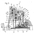
- Fig. 5 is a not inventive double clutch 10 is shown.
- These dual clutch 10 is basically constructed such that in the two coupling portions 28, 30 by the respectively associated transmission lever assemblies 61, 63 and the transmission lever 60, 62 thereof and by the actuator assemblies 70, 76, which are each configured here as slave cylinder systems, the Pressure plates 22, 56 are biased in the direction of engagement.
- the transmission lever assemblies 60, 61 may also comprise integrally connected by a ring-like region and stamped from a steel material lever elements, which may in principle be effective in the manner of a diaphragm spring, namely, that they are biased in the direction of disengagement and then counteracted against their own bias by the actuator assemblies 70, 76 in the direction of engagement, and thus transmit the biasing action of the actuator assemblies 70, 76 to the associated pressure plates 56, 58.
- the intermediate plate 22 now forms an abutment only for the coupling region 28 or the pressure plate 56 thereof.
- the intermediate plate 22 is connected in its radially outer region by bolts or the like with a further plate member 150 which is connected radially inwardly to the shaft 18.
- This plate member 150 now forms the abutment for the second coupling portion 30. It can be seen that the pressure plate 58 thereof is received in a recess 152 of the intermediate plate 22 and acted upon by a force transmission element 72 for movement in the direction of the plate member 50 and the clutch disc 42 is.
- the two pressure plates 56, 58 are thus here to obtain a state of engagement by the respective actuator assemblies 70, 76 through the intermediary of the transmission lever assemblies 60, 61 and in the case of the coupling portion 30th Also applied to the force transmission element 72 for movement in the same axial direction.
- the entire abutment region of this arrangement is thus essentially formed by the two plates 22, 150, which ultimately form a housing-like configuration by their radially outer connection.
- the loading force of the force transmission element is transmitted to the pressure plate 58 by a plurality of circumferentially successive projections which pass through various components in openings provided for this purpose.
- the housing assembly 12 here comprises two housing parts 12a and 12b.
- the housing part 12a is in its radially outer region, for example, at a plurality of circumferential positions with the intermediate plate 22 and thus also the plate member 150, generally so the abutment portion of the double clutch connected.
- the transmission lever arrangement 61 of the coupling region 28 is supported with respect to the housing part 12a in a region lying radially outwardly of the support on the pressure plate 56 via a wear adjusting device, generally designated 66.
- a wear adjusting device generally designated 66.
- the housing part 12b of the housing assembly is also fixedly coupled in its radially outer region with the intermediate plate 22 and, in turn, with the plate member 150, so it is also coupled to the abutment portion of the double clutch 10.
- On the housing part 12b is supported with its radially outer region of the transmission lever assembly 63 via a Verschl michnachstellvorraum 78, while radially within this support with respect to the pressure plate 58, namely at which the engagement force on the pressure plate 58 transmitting power transmission element 72 takes place.
- the two previously described Verschl dernachstellvortechnischen 66, 78 may be of conventional construction, for example, as described above, so at least one of wear of wear under the bias of a spring element in the circumferential direction movable and thereby axially displaceable by ramp or wedge effect or an axial displacement of another Component inducing adjusting, for example, an adjusting ring, have.
Landscapes
- Engineering & Computer Science (AREA)
- General Engineering & Computer Science (AREA)
- Mechanical Engineering (AREA)
- Mechanical Operated Clutches (AREA)
Claims (9)
- Arrangement d'embrayage multiple, notamment arrangement d'embrayage double comprenant :- un arrangement de boîtier (12) qui est accouplé ou peut être accouplé avec un organe d'entraînement (18) en vue d'une rotation commune autour d'un axe de rotation (A),- une première zone d'accouplement (28) comprenant une première plaque de compression (56) par le biais de laquelle une zone de frottement (36) d'un premier disque d'embrayage (40) peut être comprimée contre une zone de butée configurée comme plaque intermédiaire (22) et pouvant tourner avec l'arrangement de boîtier (12) ainsi qu'un premier arrangement d'éléments de positionnement (70) par le biais duquel la première zone d'accouplement (28) peut être activée pour effectuer des opérations de positionnement,- une deuxième zone d'accouplement (30) comprenant une deuxième plaque de compression (58) par le biais de laquelle une zone de frottement (38) d'un deuxième disque d'embrayage (42) peut être comprimée contre la plaque intermédiaire (22) ainsi qu'un deuxième arrangement d'éléments de positionnement (76) par le biais duquel la deuxième zone d'accouplement (30) peut être activée pour effectuer des opérations de positionnement,le premier arrangement d'éléments de positionnement (70) et le deuxième arrangement d'éléments de positionnement (76) étant configurés pour produire une force de positionnement appliquée à la zone d'accouplement (28, 30) à chaque fois associée dans le sens de l'embrayage, et la première zone d'accouplement (28) et la deuxième zone d'accouplement (30) présentant chacune un arrangement de levier de transmission (61, 63) qui peut être commandé par le premier arrangement d'éléments de positionnement (70) ou le deuxième arrangement d'éléments de positionnement (76) et qui est soutenu d'un côté par rapport à l'arrangement de boîtier (12) et d'un autre côté par rapport à la plaque de compression (56, 58) à chaque fois associée,
l'un (61) des arrangements de levier de transmission (61, 63) étant soutenu sur un côté intérieur de l'arrangement de boîtier (12) et l'autre (63) arrangement de levier de transmission (61, 63) étant soutenu sur un côté extérieur de l'arrangement de boîtier (12),
au niveau de l'une (28) des zones d'accouplement (28, 30), l'arrangement de levier de transmission (61) correspondant étant soutenu par rapport à l'arrangement de boîtier (12) dans une zone située dans le sens radial à l'extérieur du soutien par rapport à la plaque de compression (56) et au niveau de l'autre (30) zone d'accouplement (28, 30), l'arrangement de levier de transmission (63) correspondant étant soutenu par rapport à l'arrangement de boîtier (12) dans une zone située dans le sens radial à l'intérieur du soutien par rapport à la plaque de compression (58),
au niveau de l'autre (30) zone d'accouplement (28, 30) étant prévu au moins un élément de transmission (72) par le biais duquel l'arrangement de levier de transmission (63) est soutenu par rapport à la plaque de compression (58),
caractérisé en ce que
l'au moins un élément de transmission (72) est réalisé sous forme de pièce en tôle et est guidé de manière déplaçable axialement dans un évidement prévu dans la région extérieure de la plaque intermédiaire (22), et
en ce que l'arrangement de boîtier (12) présente une première partie de boîtier (14) en forme de pot prévue pour l'accouplement à l'organe d'entraînement (18) ainsi qu'une deuxième partie de boîtier (24) en forme de pot prévue pour le soutien des deux arrangements de levier de transmission (61, 63), une zone de bord (20) de la première partie de boîtier (14) en forme de pot chevauchant la plaque intermédiaire (22) pour terminer chaque évidement présentant un élément de transmission (72) dans le sens radial vers l'extérieur, et une zone de bord (26) de la deuxième partie de boîtier (24) en forme de pot étant connectée à la plaque intermédiaire (22) dans le sens radial vers l'intérieur de la connexion de la plaque intermédiaire (22) à la première partie de boîtier (14) en forme de pot, et les deux arrangements de levier de transmission étant soutenus au niveau d'une zone de fond (64) de la deuxième partie de boîtier. - Arrangement d'embrayage selon la revendication 1, caractérisé en ce que l'arrangement de levier de transmission (63) de l'autre zone d'accouplement (30) est soutenu sur le côté extérieur de l'arrangement de boîtier (12).
- Arrangement d'embrayage selon l'une des revendications 1 à 2, caractérisé en ce que la première plaque de compression (56) et la deuxième plaque de compression (58) peuvent être sollicitées dans des directions axiales opposées par le biais de l'arrangement d'éléments de positionnement (70, 76) à chaque fois associé.
- Arrangement d'embrayage selon l'une des revendications 1 à 3, caractérisé en ce qu'au moins l'un des arrangements d'éléments de positionnement (70, 76) agit sur la zone d'accouplement (28, 30) associée, de préférence la plaque de compression de cette zone d'accouplement, par le biais d'un dispositif de rattrapage de l'usure (66, 78).
- Arrangement d'embrayage selon la revendication 4, caractérisé en ce que le dispositif de rattrapage de l'usure (66, 78) comprend :- au moins un élément de rattrapage (84, 86) qui peut changer de position par rapport à la plaque de compression (56, 58) lors de l'exécution d'une opération de rattrapage de l'usure,- un premier élément de saisie (104) fixe par rapport à l'arrangement de boîtier (12),- un deuxième élément de saisie (90) maintenu contre la plaque de compression (56, 58) et pouvant être dévié par rapport à la plaque de compression (56, 58) en cas d'usure, par interaction avec le premier élément de saisie (104),- un élément d'arrêt (100) à l'aide duquel le deuxième élément de saisie (90) peut être arrêté dans sa position de déviation due à l'usure par rapport à la plaque de compression (56, 58),l'élément d'arrêt (100) pouvant être changé de position par rapport à la plaque de compression (56, 58) et par rapport au deuxième élément de saisie (104) en présence d'une usure et de la déviation ainsi produite du deuxième élément de saisie (90) et un mouvement de rattrapage de l'au moins un élément de rattrapage (84, 86) pouvant être limité par le biais du deuxième élément de saisie (90) et/ou de l'élément d'arrêt (100).
- Arrangement d'embrayage selon la revendication 5, caractérisé en ce que le deuxième élément de saisie (90) est réalisé sous la forme d'un ressort à lames et il est fixé dans une zone d'extrémité (92) sur la plaque de compression (56, 58).
- Arrangement d'embrayage selon la revendication 5 ou 6, caractérisé en ce qu'en présence d'usure, le deuxième élément de saisie (90) est éloigné d'au moins une zone longitudinale (94) en direction de la plaque de compression (56, 58), en ce que l'élément d'arrêt (100) est réalisé sous la forme d'une clavette et en ce que l'élément d'arrêt (100) en forme de clavette est précontraint par précontrainte dans un espace intermédiaire formé entre la plaque de compression (56, 58) et la zone longitudinale (94) du deuxième élément de saisie (90).
- Arrangement d'embrayage selon l'une des revendications 4 à 7, caractérisé en ce qu'au moins un élément de rattrapage (84, 86) comprend une bague de rattrapage (84, 86) qui peut tourner autour de l'axe de rotation (A) par rapport à la plaque de compression (56, 58) lors de la réalisation d'un rattrapage d'usure.
- Arrangement d'embrayage selon l'une des revendications 1 à 3, caractérisé en ce qu'au moins l'un des arrangements de levier de transmission (61, 63) est soutenu par rapport à l'arrangement de boîtier (12) par le biais d'un dispositif de rattrapage de l'usure (66, 78).
Applications Claiming Priority (5)
| Application Number | Priority Date | Filing Date | Title |
|---|---|---|---|
| DE10148176 | 2001-09-28 | ||
| DE10148176 | 2001-09-28 | ||
| DE10234548A DE10234548A1 (de) | 2001-09-28 | 2002-07-30 | Mehrfach-Kupplungsanordnung, insbesondere Doppelkupplungsanordnung |
| DE10234548 | 2002-07-30 | ||
| PCT/EP2002/010878 WO2003029677A1 (fr) | 2001-09-28 | 2002-09-27 | Systeme a plusieurs embrayages, en particulier a double embrayage |
Publications (3)
| Publication Number | Publication Date |
|---|---|
| EP1430230A1 EP1430230A1 (fr) | 2004-06-23 |
| EP1430230B1 EP1430230B1 (fr) | 2010-01-27 |
| EP1430230B2 true EP1430230B2 (fr) | 2016-01-13 |
Family
ID=26010261
Family Applications (2)
| Application Number | Title | Priority Date | Filing Date |
|---|---|---|---|
| EP02019060A Expired - Lifetime EP1298339B1 (fr) | 2001-09-28 | 2002-08-28 | Arrangement d'accouplement multiple, notamment embrayage double |
| EP02777244.1A Expired - Lifetime EP1430230B2 (fr) | 2001-09-28 | 2002-09-27 | Systeme a plusieurs embrayages, en particulier a double embrayage |
Family Applications Before (1)
| Application Number | Title | Priority Date | Filing Date |
|---|---|---|---|
| EP02019060A Expired - Lifetime EP1298339B1 (fr) | 2001-09-28 | 2002-08-28 | Arrangement d'accouplement multiple, notamment embrayage double |
Country Status (4)
| Country | Link |
|---|---|
| US (2) | US20040238307A1 (fr) |
| EP (2) | EP1298339B1 (fr) |
| AT (1) | ATE261553T1 (fr) |
| WO (1) | WO2003029677A1 (fr) |
Families Citing this family (23)
| Publication number | Priority date | Publication date | Assignee | Title |
|---|---|---|---|---|
| DE10336419A1 (de) * | 2002-08-22 | 2004-03-04 | Zf Sachs Ag | Doppelkupplungsanordnung |
| EP1582759B1 (fr) * | 2004-03-31 | 2007-03-14 | LuK Lamellen und Kupplungsbau Beteiligungs KG | Système d'actionnement hydraulique pour embrayage. |
| FR2893370B1 (fr) * | 2005-11-16 | 2009-10-30 | Valeo Embrayages | Ensemble d'embrayage multiple notamment de vehicule automobile, et procede de commande associe |
| CN101512178B (zh) * | 2006-08-31 | 2011-08-31 | 卢克资产管理有限责任公司 | 用于操作具有自补偿调节装置的摩擦离合器的装置 |
| DE102007044621A1 (de) * | 2006-10-28 | 2008-04-30 | Zf Friedrichshafen Ag | Hybrid-Antriebssystem für ein Fahrzeug |
| WO2008058508A1 (fr) * | 2006-11-17 | 2008-05-22 | Luk Lamellen Und Kupplungsbau Beteiligungs Kg | Système d'embrayage |
| CN101225867B (zh) * | 2008-01-29 | 2010-04-21 | 吉林大学 | 应用于干式双离合器上的两个飞轮 |
| US8162085B2 (en) * | 2008-12-24 | 2012-04-24 | GM Global Technologies Operations LLC | Hydro-mechanical clutch for a hybrid transmission and method for operating the same |
| KR101470028B1 (ko) * | 2009-08-27 | 2014-12-05 | 현대자동차주식회사 | Dct의 클러치 작동장치 |
| GB2474517A (en) * | 2009-10-19 | 2011-04-20 | Gm Global Tech Operations Inc | A clutch actuation device for a dual clutch including concentric slave cylinders |
| DE112010004994T5 (de) * | 2009-12-25 | 2013-01-10 | Exedy Corporation | Kupplungsvorrichtung |
| GB2476983A (en) * | 2010-01-19 | 2011-07-20 | Gm Global Tech Operations Inc | Double clutch for vehicles |
| US8297424B2 (en) * | 2010-02-05 | 2012-10-30 | GM Global Technology Operations LLC | Single actuator self-adjusting dry dual clutch |
| JP4975847B2 (ja) * | 2010-04-07 | 2012-07-11 | 株式会社エクセディ | クラッチ装置 |
| JP4975877B2 (ja) * | 2010-07-19 | 2012-07-11 | 株式会社エクセディ | クラッチ装置 |
| JP5008757B2 (ja) * | 2010-08-20 | 2012-08-22 | 株式会社エクセディ | クラッチカバー組立体 |
| FR2984434B1 (fr) | 2011-12-16 | 2014-01-10 | Valeo Embrayages | Double embrayage a rattrapage d'usure, notamment pour vehicule automobile |
| EP2828621B1 (fr) | 2012-03-23 | 2017-09-06 | Pacific Rim Engineered Products (1987) Ltd. | Mécanisme d'engagement d'engrenage pour transmissions et procédés associés |
| CN104395648B (zh) | 2012-03-23 | 2017-06-30 | 环太平洋工程产品(1987)有限公司 | 具有提供替选传动比的替选扭矩传输路径的双离合器式动力变速器 |
| DE102012207590A1 (de) * | 2012-05-08 | 2013-11-14 | Zf Friedrichshafen Ag | Kupplungsanordnung |
| EP2872788A1 (fr) * | 2012-07-12 | 2015-05-20 | Schaeffler Technologies AG & Co. KG | Dispositif d'actionnement de double embrayage |
| DE102013224328A1 (de) * | 2013-11-28 | 2015-05-28 | Schaeffler Technologies AG & Co. KG | Kupplungsvorrichtung |
| KR101862471B1 (ko) * | 2016-10-21 | 2018-05-29 | 현대다이모스(주) | 듀얼클러치 액츄에이터 |
Citations (2)
| Publication number | Priority date | Publication date | Assignee | Title |
|---|---|---|---|---|
| DE1292962B (de) † | 1961-07-01 | 1969-04-17 | Ferodo Sa | Doppelkupplung mit mindestens einer Membrankupplung |
| EP1134447A2 (fr) † | 2000-03-16 | 2001-09-19 | Mannesmann Sachs Aktiengesellschaft | Configuration de double embrayage |
Family Cites Families (11)
| Publication number | Priority date | Publication date | Assignee | Title |
|---|---|---|---|---|
| US2757557A (en) * | 1947-11-04 | 1956-08-07 | Roscoe C Hoffman | Transmission |
| FR1036741A (fr) * | 1951-02-28 | 1953-09-10 | Embrayage à action multiple | |
| DE3819702A1 (de) * | 1988-06-09 | 1989-12-14 | Porsche Ag | Hydraulisch betaetigte doppelkupplung fuer ein kraftfahrzeug |
| JP3216424B2 (ja) * | 1994-06-20 | 2001-10-09 | トヨタ自動車株式会社 | ツインクラッチ式変速機 |
| DE19703333B4 (de) * | 1997-01-30 | 2006-02-02 | Zf Sachs Ag | Reibungskupplung für Kraftfahrzeuge |
| DE19934853A1 (de) * | 1999-07-24 | 2001-02-08 | Daimler Chrysler Ag | Drehmomentübertragungssystem |
| DE10004179C5 (de) * | 1999-09-30 | 2017-06-29 | Volkswagen Ag | Mehrfach-Kupplungseinrichtung |
| BR0108393A (pt) * | 2000-02-15 | 2003-03-11 | Luk Lamellen & Kupplungsbau | Dispositivo transmissor de torque |
| DE10134118B4 (de) * | 2001-07-13 | 2013-02-21 | Volkswagen Ag | Doppelkupplung |
| DE10149704A1 (de) * | 2001-10-09 | 2003-04-10 | Zf Sachs Ag | Eingangsseitig zentral an einer Drehwelle oder Drehkomponente angebundene Kupplungseinrichtung in einem Kraftfahrzeug-Antriebsstrang |
| DE10149710A1 (de) * | 2001-10-09 | 2003-05-15 | Zf Sachs Ag | Mehrfach-Kupplungsanordnung |
-
2002
- 2002-08-28 EP EP02019060A patent/EP1298339B1/fr not_active Expired - Lifetime
- 2002-08-28 AT AT02019060T patent/ATE261553T1/de not_active IP Right Cessation
- 2002-09-27 US US10/491,029 patent/US20040238307A1/en active Granted
- 2002-09-27 EP EP02777244.1A patent/EP1430230B2/fr not_active Expired - Lifetime
- 2002-09-27 WO PCT/EP2002/010878 patent/WO2003029677A1/fr not_active Ceased
- 2002-09-27 US US10/491,029 patent/US7080722B2/en not_active Expired - Lifetime
Patent Citations (2)
| Publication number | Priority date | Publication date | Assignee | Title |
|---|---|---|---|---|
| DE1292962B (de) † | 1961-07-01 | 1969-04-17 | Ferodo Sa | Doppelkupplung mit mindestens einer Membrankupplung |
| EP1134447A2 (fr) † | 2000-03-16 | 2001-09-19 | Mannesmann Sachs Aktiengesellschaft | Configuration de double embrayage |
Also Published As
| Publication number | Publication date |
|---|---|
| US7080722B2 (en) | 2006-07-25 |
| WO2003029677A1 (fr) | 2003-04-10 |
| EP1298339B1 (fr) | 2004-03-10 |
| EP1298339A1 (fr) | 2003-04-02 |
| US20040238307A1 (en) | 2004-12-02 |
| EP1430230B1 (fr) | 2010-01-27 |
| EP1430230A1 (fr) | 2004-06-23 |
| ATE261553T1 (de) | 2004-03-15 |
Similar Documents
| Publication | Publication Date | Title |
|---|---|---|
| EP1430230B2 (fr) | Systeme a plusieurs embrayages, en particulier a double embrayage | |
| EP1989457B1 (fr) | Embrayage a friction double action dote de deux embrayages complets et leur procede d'ajustement | |
| EP1862689B2 (fr) | Agencement de transmission d'un couple de rotation pour le conducteur de commande d'un véhicule | |
| DE3013298A1 (de) | Reibungskupplungseinheit | |
| EP1134447B1 (fr) | Configuration de double embrayage | |
| DE10016607B4 (de) | Doppelkupplungsanordnung | |
| EP1851460B1 (fr) | Unite d'embrayage | |
| DE2830659A1 (de) | Kupplung | |
| EP1413795B1 (fr) | Arrangement de transfert de couple | |
| EP1512881B1 (fr) | Dispositif d'embrayage | |
| EP1862688B2 (fr) | Agencement de transmission d'un couple de rotation pour le conducteur de commande d'un véhicule | |
| DE102012213684A1 (de) | Zugankeranordnung zum Verlagern einer Anpressplatte einer Reibungskupplung | |
| EP2638306B1 (fr) | Dispositif de transmission de couple | |
| EP3655279B1 (fr) | Module hybride | |
| EP3875796B1 (fr) | Accouplement par complémentarité de forme et de friction | |
| DE10234548A1 (de) | Mehrfach-Kupplungsanordnung, insbesondere Doppelkupplungsanordnung | |
| DE102004029881A1 (de) | Elastische Anpresskraftübertragungsplatte und Herstellungsverfahren | |
| EP3161339B1 (fr) | Embrayage double multidisques humide comportant des leviers à l'extérieur de l'espace humide | |
| WO2014131415A2 (fr) | Embrayage à friction | |
| EP2087252B1 (fr) | Embrayage à friction pour la chaîne cinématique d'un véhicule | |
| DE10148427A1 (de) | Verfahren zum Justieren eines Reibungskupplungssystems | |
| EP1475550B1 (fr) | Embrayage à friction | |
| WO2003029675A1 (fr) | Ensemble plaque de pression destine a un embrayage a friction | |
| EP1876367A1 (fr) | Système d'embrayage multidisques, en particulier pour véhicules utilitaires | |
| DE10126779A1 (de) | Druckplattenbaugruppe |
Legal Events
| Date | Code | Title | Description |
|---|---|---|---|
| PUAI | Public reference made under article 153(3) epc to a published international application that has entered the european phase |
Free format text: ORIGINAL CODE: 0009012 |
|
| 17P | Request for examination filed |
Effective date: 20031212 |
|
| AK | Designated contracting states |
Kind code of ref document: A1 Designated state(s): AT BE BG CH CY CZ DE DK EE ES FI FR GB GR IE IT LI LU MC NL PT SE SK TR |
|
| GRAP | Despatch of communication of intention to grant a patent |
Free format text: ORIGINAL CODE: EPIDOSNIGR1 |
|
| GRAS | Grant fee paid |
Free format text: ORIGINAL CODE: EPIDOSNIGR3 |
|
| GRAA | (expected) grant |
Free format text: ORIGINAL CODE: 0009210 |
|
| AK | Designated contracting states |
Kind code of ref document: B1 Designated state(s): AT BE BG CH CY CZ DE DK EE ES FI FR GB GR IE IT LI LU MC NL PT SE SK TR |
|
| REG | Reference to a national code |
Ref country code: GB Ref legal event code: FG4D Free format text: NOT ENGLISH |
|
| REG | Reference to a national code |
Ref country code: CH Ref legal event code: EP |
|
| REG | Reference to a national code |
Ref country code: IE Ref legal event code: FG4D |
|
| REF | Corresponds to: |
Ref document number: 50214195 Country of ref document: DE Date of ref document: 20100318 Kind code of ref document: P |
|
| REG | Reference to a national code |
Ref country code: NL Ref legal event code: VDEP Effective date: 20100127 |
|
| PG25 | Lapsed in a contracting state [announced via postgrant information from national office to epo] |
Ref country code: ES Free format text: LAPSE BECAUSE OF FAILURE TO SUBMIT A TRANSLATION OF THE DESCRIPTION OR TO PAY THE FEE WITHIN THE PRESCRIBED TIME-LIMIT Effective date: 20100508 Ref country code: NL Free format text: LAPSE BECAUSE OF FAILURE TO SUBMIT A TRANSLATION OF THE DESCRIPTION OR TO PAY THE FEE WITHIN THE PRESCRIBED TIME-LIMIT Effective date: 20100127 Ref country code: PT Free format text: LAPSE BECAUSE OF FAILURE TO SUBMIT A TRANSLATION OF THE DESCRIPTION OR TO PAY THE FEE WITHIN THE PRESCRIBED TIME-LIMIT Effective date: 20100527 |
|
| REG | Reference to a national code |
Ref country code: IE Ref legal event code: FD4D |
|
| PG25 | Lapsed in a contracting state [announced via postgrant information from national office to epo] |
Ref country code: FI Free format text: LAPSE BECAUSE OF FAILURE TO SUBMIT A TRANSLATION OF THE DESCRIPTION OR TO PAY THE FEE WITHIN THE PRESCRIBED TIME-LIMIT Effective date: 20100127 |
|
| PG25 | Lapsed in a contracting state [announced via postgrant information from national office to epo] |
Ref country code: CY Free format text: LAPSE BECAUSE OF FAILURE TO SUBMIT A TRANSLATION OF THE DESCRIPTION OR TO PAY THE FEE WITHIN THE PRESCRIBED TIME-LIMIT Effective date: 20100127 Ref country code: IE Free format text: LAPSE BECAUSE OF FAILURE TO SUBMIT A TRANSLATION OF THE DESCRIPTION OR TO PAY THE FEE WITHIN THE PRESCRIBED TIME-LIMIT Effective date: 20100127 Ref country code: SE Free format text: LAPSE BECAUSE OF FAILURE TO SUBMIT A TRANSLATION OF THE DESCRIPTION OR TO PAY THE FEE WITHIN THE PRESCRIBED TIME-LIMIT Effective date: 20100127 Ref country code: EE Free format text: LAPSE BECAUSE OF FAILURE TO SUBMIT A TRANSLATION OF THE DESCRIPTION OR TO PAY THE FEE WITHIN THE PRESCRIBED TIME-LIMIT Effective date: 20100127 Ref country code: GR Free format text: LAPSE BECAUSE OF FAILURE TO SUBMIT A TRANSLATION OF THE DESCRIPTION OR TO PAY THE FEE WITHIN THE PRESCRIBED TIME-LIMIT Effective date: 20100428 |
|
| PLBI | Opposition filed |
Free format text: ORIGINAL CODE: 0009260 |
|
| PLAX | Notice of opposition and request to file observation + time limit sent |
Free format text: ORIGINAL CODE: EPIDOSNOBS2 |
|
| PG25 | Lapsed in a contracting state [announced via postgrant information from national office to epo] |
Ref country code: SK Free format text: LAPSE BECAUSE OF FAILURE TO SUBMIT A TRANSLATION OF THE DESCRIPTION OR TO PAY THE FEE WITHIN THE PRESCRIBED TIME-LIMIT Effective date: 20100127 Ref country code: BG Free format text: LAPSE BECAUSE OF FAILURE TO SUBMIT A TRANSLATION OF THE DESCRIPTION OR TO PAY THE FEE WITHIN THE PRESCRIBED TIME-LIMIT Effective date: 20100427 Ref country code: CZ Free format text: LAPSE BECAUSE OF FAILURE TO SUBMIT A TRANSLATION OF THE DESCRIPTION OR TO PAY THE FEE WITHIN THE PRESCRIBED TIME-LIMIT Effective date: 20100127 |
|
| 26 | Opposition filed |
Opponent name: SCHAEFFLER TECHNOLOGIES GMBH & CO. KG Effective date: 20101027 |
|
| PG25 | Lapsed in a contracting state [announced via postgrant information from national office to epo] |
Ref country code: DK Free format text: LAPSE BECAUSE OF FAILURE TO SUBMIT A TRANSLATION OF THE DESCRIPTION OR TO PAY THE FEE WITHIN THE PRESCRIBED TIME-LIMIT Effective date: 20100127 |
|
| BERE | Be: lapsed |
Owner name: ZF SACHS A.G. Effective date: 20100930 |
|
| PG25 | Lapsed in a contracting state [announced via postgrant information from national office to epo] |
Ref country code: IT Free format text: LAPSE BECAUSE OF FAILURE TO SUBMIT A TRANSLATION OF THE DESCRIPTION OR TO PAY THE FEE WITHIN THE PRESCRIBED TIME-LIMIT Effective date: 20100127 |
|
| PLAF | Information modified related to communication of a notice of opposition and request to file observations + time limit |
Free format text: ORIGINAL CODE: EPIDOSCOBS2 |
|
| PG25 | Lapsed in a contracting state [announced via postgrant information from national office to epo] |
Ref country code: MC Free format text: LAPSE BECAUSE OF NON-PAYMENT OF DUE FEES Effective date: 20100930 |
|
| REG | Reference to a national code |
Ref country code: CH Ref legal event code: PL |
|
| PLBB | Reply of patent proprietor to notice(s) of opposition received |
Free format text: ORIGINAL CODE: EPIDOSNOBS3 |
|
| PG25 | Lapsed in a contracting state [announced via postgrant information from national office to epo] |
Ref country code: LI Free format text: LAPSE BECAUSE OF NON-PAYMENT OF DUE FEES Effective date: 20100930 Ref country code: BE Free format text: LAPSE BECAUSE OF NON-PAYMENT OF DUE FEES Effective date: 20100930 Ref country code: CH Free format text: LAPSE BECAUSE OF NON-PAYMENT OF DUE FEES Effective date: 20100930 |
|
| PG25 | Lapsed in a contracting state [announced via postgrant information from national office to epo] |
Ref country code: AT Free format text: LAPSE BECAUSE OF NON-PAYMENT OF DUE FEES Effective date: 20100927 |
|
| PG25 | Lapsed in a contracting state [announced via postgrant information from national office to epo] |
Ref country code: LU Free format text: LAPSE BECAUSE OF NON-PAYMENT OF DUE FEES Effective date: 20100927 |
|
| PG25 | Lapsed in a contracting state [announced via postgrant information from national office to epo] |
Ref country code: TR Free format text: LAPSE BECAUSE OF FAILURE TO SUBMIT A TRANSLATION OF THE DESCRIPTION OR TO PAY THE FEE WITHIN THE PRESCRIBED TIME-LIMIT Effective date: 20100127 |
|
| RAP2 | Party data changed (patent owner data changed or rights of a patent transferred) |
Owner name: ZF FRIEDRICHSHAFEN AG |
|
| REG | Reference to a national code |
Ref country code: DE Ref legal event code: R081 Ref document number: 50214195 Country of ref document: DE Owner name: ZF FRIEDRICHSHAFEN AG, DE Free format text: FORMER OWNER: ZF SACHS AG, 97424 SCHWEINFURT, DE Effective date: 20121030 |
|
| APBM | Appeal reference recorded |
Free format text: ORIGINAL CODE: EPIDOSNREFNO |
|
| APBP | Date of receipt of notice of appeal recorded |
Free format text: ORIGINAL CODE: EPIDOSNNOA2O |
|
| APAH | Appeal reference modified |
Free format text: ORIGINAL CODE: EPIDOSCREFNO |
|
| APBQ | Date of receipt of statement of grounds of appeal recorded |
Free format text: ORIGINAL CODE: EPIDOSNNOA3O |
|
| PLAB | Opposition data, opponent's data or that of the opponent's representative modified |
Free format text: ORIGINAL CODE: 0009299OPPO |
|
| R26 | Opposition filed (corrected) |
Opponent name: SCHAEFFLER TECHNOLOGIES GMBH & CO. KG Effective date: 20101027 |
|
| PLAB | Opposition data, opponent's data or that of the opponent's representative modified |
Free format text: ORIGINAL CODE: 0009299OPPO |
|
| R26 | Opposition filed (corrected) |
Opponent name: SCHAEFFLER TECHNOLOGIES AG & CO. KG Effective date: 20101027 |
|
| PLAB | Opposition data, opponent's data or that of the opponent's representative modified |
Free format text: ORIGINAL CODE: 0009299OPPO |
|
| R26 | Opposition filed (corrected) |
Opponent name: SCHAEFFLER TECHNOLOGIES GMBH & CO. KG Effective date: 20101027 |
|
| REG | Reference to a national code |
Ref country code: GB Ref legal event code: 732E Free format text: REGISTERED BETWEEN 20150326 AND 20150401 |
|
| REG | Reference to a national code |
Ref country code: FR Ref legal event code: PLFP Year of fee payment: 14 |
|
| APBU | Appeal procedure closed |
Free format text: ORIGINAL CODE: EPIDOSNNOA9O |
|
| PUAH | Patent maintained in amended form |
Free format text: ORIGINAL CODE: 0009272 |
|
| STAA | Information on the status of an ep patent application or granted ep patent |
Free format text: STATUS: PATENT MAINTAINED AS AMENDED |
|
| 27A | Patent maintained in amended form |
Effective date: 20160113 |
|
| AK | Designated contracting states |
Kind code of ref document: B2 Designated state(s): AT BE BG CH CY CZ DE DK EE ES FI FR GB GR IE IT LI LU MC NL PT SE SK TR |
|
| REG | Reference to a national code |
Ref country code: DE Ref legal event code: R102 Ref document number: 50214195 Country of ref document: DE |
|
| REG | Reference to a national code |
Ref country code: FR Ref legal event code: PLFP Year of fee payment: 15 |
|
| REG | Reference to a national code |
Ref country code: FR Ref legal event code: PLFP Year of fee payment: 16 |
|
| REG | Reference to a national code |
Ref country code: FR Ref legal event code: PLFP Year of fee payment: 17 |
|
| PGFP | Annual fee paid to national office [announced via postgrant information from national office to epo] |
Ref country code: FR Payment date: 20190815 Year of fee payment: 18 Ref country code: DE Payment date: 20190917 Year of fee payment: 18 |
|
| PGFP | Annual fee paid to national office [announced via postgrant information from national office to epo] |
Ref country code: GB Payment date: 20190926 Year of fee payment: 18 |
|
| REG | Reference to a national code |
Ref country code: DE Ref legal event code: R119 Ref document number: 50214195 Country of ref document: DE |
|
| GBPC | Gb: european patent ceased through non-payment of renewal fee |
Effective date: 20200927 |
|
| PG25 | Lapsed in a contracting state [announced via postgrant information from national office to epo] |
Ref country code: DE Free format text: LAPSE BECAUSE OF NON-PAYMENT OF DUE FEES Effective date: 20210401 Ref country code: FR Free format text: LAPSE BECAUSE OF NON-PAYMENT OF DUE FEES Effective date: 20200930 |
|
| PG25 | Lapsed in a contracting state [announced via postgrant information from national office to epo] |
Ref country code: GB Free format text: LAPSE BECAUSE OF NON-PAYMENT OF DUE FEES Effective date: 20200927 |