EP1430271B1 - Verfahren und einrichtung zur messung mindestens einer geometrischen grösse einer optisch reflektierenden oberfläche - Google Patents
Verfahren und einrichtung zur messung mindestens einer geometrischen grösse einer optisch reflektierenden oberfläche Download PDFInfo
- Publication number
- EP1430271B1 EP1430271B1 EP02783219.5A EP02783219A EP1430271B1 EP 1430271 B1 EP1430271 B1 EP 1430271B1 EP 02783219 A EP02783219 A EP 02783219A EP 1430271 B1 EP1430271 B1 EP 1430271B1
- Authority
- EP
- European Patent Office
- Prior art keywords
- points
- camera
- image
- measured
- curvature
- Prior art date
- Legal status (The legal status is an assumption and is not a legal conclusion. Google has not performed a legal analysis and makes no representation as to the accuracy of the status listed.)
- Expired - Lifetime
Links
- 238000000034 method Methods 0.000 title claims description 47
- 230000008569 process Effects 0.000 claims description 16
- 230000003287 optical effect Effects 0.000 claims description 6
- 239000003086 colorant Substances 0.000 claims description 5
- 238000005259 measurement Methods 0.000 description 38
- 239000013598 vector Substances 0.000 description 11
- 239000000523 sample Substances 0.000 description 5
- 238000005452 bending Methods 0.000 description 3
- 230000010363 phase shift Effects 0.000 description 3
- 230000015556 catabolic process Effects 0.000 description 2
- 238000006731 degradation reaction Methods 0.000 description 2
- 238000005530 etching Methods 0.000 description 2
- 230000009466 transformation Effects 0.000 description 2
- 230000001131 transforming effect Effects 0.000 description 2
- 230000004075 alteration Effects 0.000 description 1
- 238000006243 chemical reaction Methods 0.000 description 1
- 230000007547 defect Effects 0.000 description 1
- 230000001419 dependent effect Effects 0.000 description 1
- 238000009760 electrical discharge machining Methods 0.000 description 1
- 238000009432 framing Methods 0.000 description 1
- 238000005305 interferometry Methods 0.000 description 1
- 238000000691 measurement method Methods 0.000 description 1
- 239000002184 metal Substances 0.000 description 1
- 230000004048 modification Effects 0.000 description 1
- 238000012986 modification Methods 0.000 description 1
- 238000009304 pastoral farming Methods 0.000 description 1
- 238000005498 polishing Methods 0.000 description 1
- 239000007787 solid Substances 0.000 description 1
- 230000002123 temporal effect Effects 0.000 description 1
- 230000000007 visual effect Effects 0.000 description 1
Images



Classifications
-
- G—PHYSICS
- G01—MEASURING; TESTING
- G01B—MEASURING LENGTH, THICKNESS OR SIMILAR LINEAR DIMENSIONS; MEASURING ANGLES; MEASURING AREAS; MEASURING IRREGULARITIES OF SURFACES OR CONTOURS
- G01B11/00—Measuring arrangements characterised by the use of optical techniques
- G01B11/24—Measuring arrangements characterised by the use of optical techniques for measuring contours or curvatures
- G01B11/25—Measuring arrangements characterised by the use of optical techniques for measuring contours or curvatures by projecting a pattern, e.g. one or more lines, moiré fringes on the object
- G01B11/2513—Measuring arrangements characterised by the use of optical techniques for measuring contours or curvatures by projecting a pattern, e.g. one or more lines, moiré fringes on the object with several lines being projected in more than one direction, e.g. grids, patterns
-
- G—PHYSICS
- G01—MEASURING; TESTING
- G01B—MEASURING LENGTH, THICKNESS OR SIMILAR LINEAR DIMENSIONS; MEASURING ANGLES; MEASURING AREAS; MEASURING IRREGULARITIES OF SURFACES OR CONTOURS
- G01B11/00—Measuring arrangements characterised by the use of optical techniques
- G01B11/24—Measuring arrangements characterised by the use of optical techniques for measuring contours or curvatures
- G01B11/25—Measuring arrangements characterised by the use of optical techniques for measuring contours or curvatures by projecting a pattern, e.g. one or more lines, moiré fringes on the object
- G01B11/2504—Calibration devices
Definitions
- the present invention relates to a method and a device for measuring at least one geometrical size of an optically reflective surface.
- One of these methods consists in using an optical device comprising a camera oriented towards the surface to be observed, this camera connected to a computer generates an image in levels of gray highlighting the variations of curvature of the surface.
- Devices of this type marketed for example under the trademarks DIFFRACTO®, ONDULE®, are generally used for optically reflective surfaces and make it possible to carry out qualitative surveys using grayscale images. These devices thus make it possible to visualize small variations of slope or curvature by using the principle of specular reflection, but they do not make it possible to obtain quantitative readings of geometric quantities of these variations. It is thus impossible to know the value of the slopes or curvatures of the optically reflective surfaces.
- a first method consists in using a mechanical probe in relative motion with respect to the optically reflective surface to be measured.
- This mechanical probe is calibrated so that it can be matched to each movement of its measuring finger one or more geometric quantities of the surface.
- the finger of the mechanical probe generally follows a predetermined path to scan the entire surface. It is thus possible to measure the geometric magnitude or sizes of the trajectory followed along the axis of the mechanical probe.
- the major drawbacks of this method are on the one hand the time necessary to measure the surface, on the other hand the inaccuracy related to the limited number of measuring points, and finally the risks of degradation of the surface state of the fact. of his contact with the finger of the mechanical probe.
- a second known method uses interferometry techniques and consists in comparing two waves coming from the same laser, one reflected by the surface to be measured, the other said reference coming directly from the laser.
- This second method is, like the previous one, well suited to the measurement of small surfaces.
- this process is particularly time-consuming and expensive.
- this method is only suitable for optically perfect reflective surfaces which is not the case, for example, car body panels.
- the present invention aims at overcoming these drawbacks by proposing a method and a device for measuring at least one geometrical quantity of an optically reflective, fast, reliable, precise surface, making it possible to quantify the curvatures and / or the slopes and reliefs of the optically reflective surface without risk of degradation of the surface measured and adapted to the measurement of optically reflective surfaces of large dimensions.
- the invention relates to a method as defined in the preamble during which the image of the optically reflecting surface to be measured S is observed with the aid of a camera and characterized in that this method comprises at least one calibration phase and at least one measurement phase, in that the calibration phase is performed so as to allow the interpretation of the image of the surface to be measured S seen by the camera during the measurement phase and thus transforming this image into quantitative values characterizing at least one geometrical quantity of the optically reflective surface S to be measured.
- a measurement space is advantageously defined, to which a spatial coordinate system O, X, Y, and orthonormal Z is associated.
- At least one optically reflecting surface of reference P, Ci is provided in this measurement space.
- the camera is arranged so that its field of vision covers the measurement space and we visualize an image associated with a plane reference O ', X', Y ', we have a target associated with a reference O ", X", Y "plane and having reference points M" i so that its reference points M "i are reflected on said reference P, Ci, or to measure S at points Mi, it is observed with the camera the points seen M'i image of the reference points M "i after reflection on the reference surface P, Ci, or to measure S at the points Mi and we establish a unique correspondence between the points seen M'i and the reference points M" i.
- the calibration phase preferably comprises a plane calibration step during which a unique correspondence is established between the coordinates x ', y' of the points seen M'i and the coordinates x, y of the points Mi whose coordinate according to the Z axis is known.
- the calibration phase comprises a curvature calibration step for which the camera is arranged so that its field of vision is grazing relative to the reference surface Ci, the pattern is arranged so that it is located opposite the camera with respect to the reference surface Ci and the camera is focussed substantially at the reference surface Ci.
- At least one reference standard of curvature Ci having at least one known curvature 1 / Ri according to one of the axes X, Y is used as reference surface, the points observed with the camera are observed. image of the reference points M "i of the test pattern after reflection on the curvature standard Ci at points Mi and a unique correspondence is established between the values measured at the points seen M'i or their variations and the curvature 1 / Ri of the Curvature standard Ci.
- the pattern comprises a coding of intensity Ii and / or of variable color from one point to another of the surface of the pattern, this variation being defined by a known function along at least one axis X ", Y" of the test pattern, we observe with the camera the points seen M'i image of the reference points M "i of the test pattern after reflection on the curvature standard Ci at points Mi and we establish a unique correspondence between the intensity I'i measured and / or the measured color or their variation at the points seen M'i and the curvature 1 / Ri of the curvature standard Ci.
- the curvature standard Ci forming the reference surface is preferably moved to different positions of the measuring space and the observation of the image seen by the camera and the establishment of the single correspondence in a number of points Mi determined according to the desired accuracy for said single match. It is then possible to use several curvature standards Ci each having a curvature 1 / Ri different.
- the optically reflective measuring surface S is advantageously placed in the measuring space, the points seen M i image of the reference points M are observed with the camera. i of the test pattern after reflection on the surface to be measured S at the points Mi and we deduce the curvature 1 / Ri at the points Mi according to the unique correspondence laws from the calibration phase.
- the calibration phase comprises a slope calibration step for which the pattern is placed substantially opposite the measurement space and the camera so that its optical center is disposed substantially in the vicinity of the test pattern. and at least one reference plane P substantially parallel to the test pattern and having a coordinate along the known Z axis is used as the reference surface.
- a reference plane P is preferably used to use a substantially plane mirror of coordinates Z 1 along the axis Z, the points seen M i image of the reference points M i after reflection are observed with the camera. on the reference surface P at the points Mi and we establish the unique correspondence between the coordinates x ', y' of the points seen M'i and the coordinates x, y of the points Mi whose coordinate along the Z axis is known.
- the pattern comprises a coding of intensities I, I, I, and / or of variable colors from one point to the other of its surface, these variations being defined by known functions according to the axes X "and Y "of the target, we observe with the camera the points seen M'i image of the reference points M" i after reflection on the mirror at the points Mi and we establish the unique correspondences between on the one hand the intensity ix, I'iy measured and / or measured colors or their variations at the points seen M'i and the coordinate zi of the reference plane P and secondly the coordinates xi, yi of the point Mi.
- the optically reflective measuring surface S is placed in the measuring space, the points seen by the image of the reference points M "i are observed with the camera. After reflection on the surface to be measured S at the points Mi, we deduce the coordinates xi, yi, zi at the points Mi according to the unique correspondence laws from the calibration phase and we deduce the slopes Pix, Piy respectively along the X and Y axes between two neighboring points Mi.
- the invention also relates to a device for implementing the method for measuring at least one geometrical quantity of an optically reflecting surface S to be measured as defined in the preamble, characterized in that it comprises at least one gap space.
- the invention relates to a method and a device for quantifying, by means of metric data, at least one geometrical quantity of an optically reflective surface S to be measured.
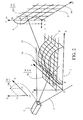
- Measurement space 1 illustrated by the figure 1 is defined beforehand. It is associated with a spatial reference O, X, Y, orthonormal Z of origin O, axes X, Y, Z.
- this measurement space 1 is provided an optically reflective surface with reference P, Ci, or measure S and a camera 2 so that its field of vision 3 covers the measurement space 1.
- This camera 2 can display an image that is associated with a plane reference O ', X', Y '.
- This method comprises at least one calibration phase and one measurement phase.
- the calibration phase makes it possible to interpret the image of the surface to be measured S seen by the camera 2 and transform this image into quantitative values characterizing one or more geometrical magnitudes of the surface to be measured.
- a pattern 6, 10 associated with a planar coordinate O ", X", Y “and having reference points M” i are provided so that these reference points M "i are reflected on the surface of reference P, Ci at points Mi and we observe the points seen M'i image of the points Mi. Then we establish unique correspondences between these points seen M'i and the reference points M "i, the nature of these unique correspondences dependent the method used.
- This calibration phase can indeed be carried out according to two different methods, making it possible for one to measure curvatures and for the other to measure slopes. These two calibration methods and the corresponding measurement phases are detailed below.
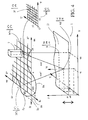
- a first method of calibration in curvature particularly well adapted to locally detect curvatures 1 / Ri and in particular to detect any defect in curvature one orients as illustrated by the figure 2 the camera 2 so that its field of view 3 is flush with respect to the reference surface P, Ci.
- the curvature calibration method may include an optional step of plan calibration.
- This step illustrated by the figure 1 , consists of calibrating a reference plane P comprising points of coordinates xi, yi, in the spatial reference frame O, X, Y, Z whose coordinate zi along the Z axis is known.
- This optional step will, if necessary, to know in addition to the curvature 1 / Ri at a point Mi, its coordinates xi, yi. Depending on the field of application, the knowledge of these coordinates xi, yi will be necessary or not.
- a target 5 constituted by any surface is placed substantially in the reference plane P, which makes it possible to ensure a single correspondence between one of its points Mi and the point viewed M'i corresponding to its picture.
- This unique correspondence is for example established by means of a pattern with known dimensional parameters.
- This pattern may for example be constituted by one or more line networks forming for example a grid.
- This motif can also be constituted as illustrated on the figure 1 by a network of dots or by any other pattern made visible on the surface of the pattern 5 by any known marking or etching process such as, for example, printing, etching, etc. It is also possible to use a pattern bearing a pattern whose dimensional parameters are not known at the beginning and for which a preliminary operation is carried out to determine these dimensional parameters, by any known measurement method.
- the points seen M'i images of the points Mi of the pattern 5 substantially coinciding with the reference plane P. are visualized.
- This image is processed so as to define the coordinates x'i, y '. i from each point seen M'i in the plane reference O ', X', Y 'of the image.
- Each point seen M'i corresponds, for example, to a given pixel of the camera 2.
- a second step of bending calibration illustrated by the figure 2 consists in calibrating the image seen by the camera 2 according to a reference surface Ci.
- a reference surface Ci is used, for example constituted by at least one standard of curvature Ci whose curvature 1 / Ri is known, Ri being the radius of curvature.
- a series of curvature standards Ci formed for example of solid metal parts, each having a face corresponding to a portion of a cylinder or parabola of known curvatures 1 / Ri, is used.
- These standards of curvature Ci are for example obtained by a spark erosion process and their faces can be rendered reflective by polishing.
- the curvature standards Ci used are chosen to have curvatures 1 / Ri framing the different curvatures expected on the surface to be measured S.
- the reference points M "i of the target 6 may be materialized by markings, for example circles whose centers have coordinates x" i, y "i known in the planar coordinate O", X ", Y".
- the pattern 6 may also include a coding intensity Ii and / or color, variable from one point to another of its surface.
- the variation of intensity Ii and / or of color on the surface of the pattern 6 may be defined by a predetermined function along at least the Y "axis of the pattern 6 and correspond for example to a sinusoidal function fi. is arbitrarily represented on the figure 2 by a grid.
- a standard of curvature Ci is placed in the measurement space 1 and the camera 2 is focused on this curvature standard Ci.
- the observed points with the camera 2 are observed M'i, images of the reference points M. 6, after reflection on the curvature standard Ci at the points Mi, a unique correspondence is established between the variations of the values measured at the points seen M'i and the known curvature 1 / Ri of the curvature standard Ci.
- the curvature standard Ci is moved to different positions of the measurement space 1 and the observation of the image seen by the camera 2 and the establishment of the unique correspondence are repeated. each having a different curvature 1 / Ri and the observation of the viewed image is repeated by the camera 2 and the establishment of the unique correspondence.
- This step carried out at some points Mi of the reference plane with several standards of different curvatures 1 / Ri allows to deduce a general law valid for any point Mi and any curvature 1 / Ri in the desired curvature range.
- the number of measurement points Mi will be determined according to the desired accuracy for the single match.
- the curvature standard Ci is placed so that its generatrix Gi coincides with the reference plane P is substantially parallel to the axis Y and the focusing of the camera 2 is carried out. substantially on the curvature standard Ci.
- the curvature 1 / Ri deduced will therefore correspond substantially to the curvature 1 / Rix along the X axis.
- the pattern 6 comprises an intensity coding Ii varying from one point to another of its surface.
- This variation follows for example a sinusoidal function fi represented on the figure 2 connecting in a known manner the luminous intensity Ii of each reference point M "i to its phase ⁇ i by a method such as the time phase offset, the spatial phase shift, or by direct phase calculation by means of the transform of Fourier of the image constituted by the values measured at the points seen M'i, we establish a unique correspondence between the intensity i i observed at the points seen M'i, image of the points reference M "i, with the phase ⁇ i.
- this operation is performed simultaneously or not for all or part of the points seen M'i of the image. In general, this operation is carried out on as many points seen M'i corresponding to measuring points as there are pixels concerned by the curvature standard Ci.
- the derivative of the phase ⁇ i substantially along the X axis is determined between the points seen M'i near, or neighboring pixels.
- a simple method for performing this derivative substantially along the X axis consists in drifting along the axis Y ' of the plane reference O ', X', Y 'bound to the image seen by the camera 2.
- This derivative is generally constant over the entire surface of the curvature standard Ci.
- this phase variation ⁇ i obtained is combined with the curvature 1 / Rix along the X axis of the curvature standard Ci at the point Mi.
- the curvature standard Ci is placed at different points of the measuring space 1 so as to measure at different points the variation of ⁇ i in the measuring space 1.
- a second standard of curvature Ci + 1 (not shown) of curvature 1 / Ri + 1 is also used, with which these same steps are repeated, then possibly with other standards of curvature of different curvatures, until it is possible to establish a general law for transforming the phase variation ⁇ i into curvature 1 / Rix, the phase variation ⁇ i being the variation between the phases ⁇ i observed by means of the camera 2.
- This phase variation ⁇ i is calculated between neighboring pixels representing neighboring Mi points and offset with respect to each other substantially along the X axis, 1 / Rix being the corresponding curvature of the curvature standard Ci or of the surface to be measured S at the point Mi along the X axis.
- This general law of transformation can be expressed by means of a mathematical equation.
- the general law of transformation of the phase variation ⁇ i into curvature 1 / Rix makes it possible, by measuring the phases ⁇ i and then by calculating the phase variations ⁇ i in along the X axis, at any point E of the surface to be measured S situated substantially in the plane P, to know the curvature 1 / Rix along the X axis at each of these points Mi. This law will be recorded and the parameters of the assembly will be fixed to carry out the measuring step .
- the pattern 6 can be obtained, as illustrated by the figure 3 by projection by means of a projection device 8 of a target 9 on an intermediate plane 7.
- the reference points M * i of the target 9 are thus projected to the points M "i of the test pattern 6 and, after reflection at the points Mi of the surface to be measured S, are observed on the image of the camera 2 at the points seen M'i or pixels.
- the bending measurement phase of the optically reflective measuring surface S is carried out.
- the surface to be measured S is placed in the measuring space 1, the observed points M'i image of the reference points M "i of the test pattern 6 are observed with the camera 2 after reflection on the surface to be measured S at the points Mi, and the curvature 1 / Ri at the points Mi of the surface to be measured S is deduced as a function of the single correspondence law or laws originating from the preceding curvature calibration phase or phases.
- slope calibration particularly well suited for measuring geometric quantities of a large surface to be measured S optically reflective located in the measurement space 1, it is arranged as illustrated by the figure 4 a substantially planar pattern 10 and plane reference O ", X", Y ", substantially opposite the measurement space 1 and the camera 2 so that its optical center is disposed substantially in the vicinity of the target 10.
- the target 10 may also comprise patterns calibrated at the origin or requiring a calibration operation as in the previous example
- This pattern 10 may comprise, as the pattern 6, a coding of different intensities of the same color or a coding of
- at least one reference plane P substantially parallel to the pattern 10 and having a coordinate along the known axis Z is used as reference surface,
- This reference plane P is, for example, a substantially plane mirror 12 of coordinate zi according to FIG. known Z axis.
- the first step of the slope calibration illustrated by the figure 4 consists in performing a calibration of the plane making it possible to establish a unique correspondence between the coordinates of the points Mi in the spatial coordinate system O, X, Y, Z and whose coordinate along the Z axis is known and the coordinates of the points seen M'i in the plane reference O ', X', Y '.
- this step is essential.
- the coordinates x "c, y" c are measured or determined empirically, for example by writing that the points Mc, M'c and M "c are aligned, M'c being the image of Mc after reflection on the mirror 12 in Mc, and / or that the measure in M'c is independent of zc.
- a second step of slope calibration also illustrated by the figure 4 It consists in calibrating the Z axis.
- the mirror 12 forming the reference plane P is moved parallel to itself in various known zi coordinates of the measurement space 1 and the observation of the mirror is repeated. image seen with the camera 2 and the establishment of the single match for zi coordinates along the Z axis different.
- the coordinates x'i and y'i of the point seen M i are measured, image of the reference point M "i after reflection on the mirror 12, from which the coordinates xi, yi of the point M are deduced.
- the mirror 12 of coordinate zi along the axis Z.
- the pattern 10 comprises a coding of luminous intensities Iix and Iiy respectively along the X ", Y" axes, these intensities varying from one point to the other of its surface.
- These variations are for example made by means of two sinusoidal functions fix and fiy.
- the fix function connects in known manner the luminous intensity Iix along the axis X "and x" i, by means for example of the phase ⁇ ix if Iix is modulated sinusoidally along the axis X ".
- the function fiy connects in a known manner the luminous intensity Ii1 along the axis Y "and y" i, by means for example of the phase ⁇ iy if Iiy is modulated sinusoidally along the axis Y. These sinusoidal functions fix, fiy may be present simultaneously or successively on the target 10.
- the measuring surface S is optically reflective and at least the coordinate zr along the axis Z of at least one point M. is measured in the measuring space 1.
- a mechanical stop or at any point on the surface to be measured S whose coordinate zr is known and measured separately, for example by means of a sensor.
- We observe with the camera 2 the point seen M'r, image of the reference point M "r of the target 10 after reflection on the surface S at the point Mr.
- the point Mr we observe the coordinates x'r, y'r from the corresponding point M'r. Knowing the coordinate zr along the Z axis, we deduce, thanks to the previous single correspondence, the coordinates xr, yr of the point Mr in the spatial coordinate system O, X Y Z.
- Nr with Mr "reference point of the target 10 whose image is the point seen Mr 'forming after reflection on the surface to be measured S at the point Mr whose coordinate zr is known along the Z axis, mrmr" the unit vector collinear to MrM "r, mrmr 'the colinear unitary vector to MrM” c.
- this relation gives a system of equations making it possible to determine the normal vector Nr in Mr at the surface to be measured S, hence the slopes Prx, Pry along the X and Y axes at this point.
- a third step consider a point Mr + 1 neighbor of Mr of which one decides temporarily and arbitrarily that the theoretical coordinate zr + 1th according to the axis Z is approximately equal to zr.
- We measure the intensities I'ix and I'iy which we determine the coordinates x "r + 1 and y" r + 1 of the reference point M "r + 1 1 of the target 10.
- the set of slopes Pix, Piy along the X and Y axes and the set of coordinates xi, yi are thus defined for each of the points of the surface to be measured. zi points Mi seen at the points M'i by the camera 2.
- the slopes Pix, Piy of any intermediate point with two measured points can be obtained by interpolation of the slopes of the measured neighboring points. It is thus possible to determine at every point Mi of the surface to be measured S the slopes Pix, Piy respectively along the axes X, Y
- the camera 2 is associated with a computer unit (not shown) arranged to interpret the image of the optically reflecting surface to be measured S seen by the camera 2 and deducing therefrom quantitative values characterizing at least one geometric magnitude of the surface to be measured S as a function of at least one reference surface P, Ci, a photograph of the camera 2 making it possible to display all the points of the surface to be measured S .
- the method according to the present invention allows the calibrated measurement device to measure one or more large geometrical quantities of large optically reflective surfaces rapidly and precisely by determining, according to the method used, the curvature of a point of the surface to be measured or the slope at each point of the surface to be measured optically reflective and the position in the measuring space of each of these points.
Landscapes
- Engineering & Computer Science (AREA)
- Computer Vision & Pattern Recognition (AREA)
- Physics & Mathematics (AREA)
- General Physics & Mathematics (AREA)
- Length Measuring Devices By Optical Means (AREA)
Claims (10)
- Verfahren zur Messung mindestens einer geometrischen Größe einer zu messenden optisch reflektierenden Fläche (S), in dem man mittels einer Kamera (2) das Bild der besagten zu messenden Fläche (S) misst, wobei dieses Verfahren aus mindestens einer Mess-Phase besteht, der mindestens eine Kalibrierungs-Phase vorausgeht, wobei die besagte Kalibrierungs-Phase erfolgt, um die Auswertung des Bilds der während der besagten Mess-Phase von der besagten Kamera (2) gesehenen besagten zu messenden Fläche (S) zu ermöglichen und somit dieses Bild in quantitative Werte umzuwandeln, die für eine Vielzahl Punkte, die die besagte zu messende optisch reflektierende Fläche (S) bilden, für jeden dieser Punkte mindestens eine der in der Gruppe bestehend aus der Neigung, der Krümmung, der Raumlage gewählten geometrischen Größen kennzeichnen, Verfahren nach welchem, um die besagte Kalibrierungs-Phase durchzuführen, man einen Mess-Bereich (1) festlegt, dem man ein räumliches Bezugssystem (O, X, Y, Z) zuweist, man in dem besagten Messbereich (1) mindestens eine optisch reflektierende Bezugsfläche (P, Ci) anordnet, man die besagte Kamera (2) so anordnet, dass ihr Sichtfeld (3) den besagten Mess-Bereich (1) abdeckt und die besagte Bezugsfläche (P, Ci) sieht, man dem besagten, von der besagten Kamera (2) gesehenen Bild ein flaches Bezugssystem (O', X', Y') zuweist, man ein mit einem flachen Bezugssystem (O", X", Y") zusammenarbeitendes und mit Bezugspunkten (M"i) versehenes Rasterbild (6, 10) anordnet, so dass sich die besagten Bezugspunkte (M"i) auf der besagten Fläche (P, Ci) an Punkten (Mi) widerspiegeln, man mit der besagten Kamera (2) die gesehenen Punkte (M'i) beobachtet, die ein Abbild der besagten Bezugspunkte (M"i) nach deren Spiegelung auf der besagten Fläche (P, Ci) an den besagten Punkten (Mi) darstellen, und man eine eindeutige Übereinstimmung zwischen den besagten gesehenen Punkten (M'i) und den besagten Bezugspunkten (M"i) herstellt, dadurch gekennzeichnet, dass die besagte Kalibrierungs-Phase einen Schritt der Kalibrierung in einer Ebene beträgt, während dem man eine eindeutige Übereinstimmung herstellt zwischen den Koordinaten (x', y') der besagten gesehenen Punkte (M'i) und den Koordinaten (x, y) der besagten Punkte (Mi), deren Z-Achsen-Koordinate bekannt ist, und dadurch, dass die besagte Kalibrierungs-Phase einen Schritt der Kalibrierung auf einer Neigung beträgt, bei welcher man das besagte Rasterbild (10) merklich gegenüber des besagten Mess-Bereichs (1) anordnet und man die besagte Kamera (2) so anordnet, dass sich ihr optisches Zentrum merklich in der Nähe des besagten Rasterbilds (10) befindet, dadurch, dass man als Bezugsfläche mindestens eine Bezugsebene (P) verwendet, die aus einem zum besagten Rasterbild (10) merklich parallelen Spiegel (12) mit bekannter Z-Achsen-Koordinate zi besteht, dadurch, dass man mit der besagten Kamera (2) die besagten gesehenen Punkte (M'i) beobachtet, die ein Abbild der besagten Bezugspunkte (M"i) des besagten Rasterbilds (10) nach deren Spiegelung auf der besagten Bezugsfläche (P) an den besagten Punkten (Mi) darstellen, und dadurch, dass man die besagte eindeutige Übereinstimmung zwischen den Koordinaten (x', y') der besagten gesehenen Punkte (M'i) und den Koordinaten (x, y) der besagten Punkte (Mi), deren Z-Achsen-Koordinate bekannt ist, herstellt.
- Verfahren nach Anspruch 1, dadurch gekennzeichnet, dass man den besagten Spiegel (12), der die besagte Bezugsebene (P) bildet, zu sich selbst parallel in verschiedene zi-Koordinaten des besagten Mess-Bereichs (1) verschiebt und dadurch, dass man die Beobachtung des mit der besagten Kamera (2) gesehenen Bilds und die Herstellung der besagten eindeutigen Übereinstimmung wiederholt.
- Verfahren nach einem beliebigen der Ansprüche 1 oder 2, dadurch gekennzeichnet, dass, um die Neigung der besagten Fläche an einer Vielzahl von Punkten zu messen, man die besagte zu messende optisch reflektierende Fläche (S) in den besagten Mess-Bereich (1) legt, man mit der besagten Kamera (2) die besagten Punkte (M'i) beobachtet, die ein Abbild der besagten Bezugspunkte (M"i) des besagten Rasterbilds (10) nach deren Spiegelung auf der besagten zu messenden Fläche (S) an den besagten Punkten (Mi) darstellen, und man daraus die Koordinaten (xi, yi, zi) an den besagten Punkten (Mi) gemäß den besagten aus der besagten Kalibrierungs-Phase erhaltenen eindeutigen Übereinstimmungsgesetzen und die Neigungen (Pix, Piy) auf der X- bzw. Y-Achse an den Punkten (Mi) ableitet.
- Verfahren nach Anspruch 1, dadurch gekennzeichnet, dass das besagte Rasterbild (10) eine Kodierung mit variablen Intensitäten (Iix, Iiy) und/oder Farben von einem Punkt zu einem anderen seiner Fläche aufweist, wobei diese Variationen durch bekannte Funktionen nach der besagten X"- bzw. Y"-Achse des besagten Rasterbilds (10) definiert sind, dadurch, dass man mit der besagten Kamera (2) die besagten gesehenen Punkte (M'i) beobachtet, die ein Abbild der besagten Bezugspunkte (M"i) nach deren Spiegelung auf dem besagten Spiegel (12) an den Punkten (Mi) darstellen, und dadurch, dass man die eindeutigen Übereinstimmungen herstellt zwischen einerseits den gemessenen Intensitäten (I'ix, I'iy) und/oder den gemessenen Farben oder deren Variationen an den besagten gesehenen Punkten (M'i), der besagten Koordinate zi der besagten Bezugsebene (P) und andererseits den Koordinaten xi, yi des besagten Punkts (Mi).
- Verfahren nach Anspruch 1, dadurch gekennzeichnet, dass die besagte Kalibrierungs-Phase einen Kalibrierungs-Schritt auf einer Wölbung beträgt, für den man die besagte Kamera (2) so anordnet, dass ihr Sichtfeld (3) in Bezug auf die besagte Bezugsfläche (Ci) streifend ist, man das besagte Rasterbild (6) so anordnet, dass es sich in Bezug auf die besagte Bezugsfläche (Ci) auf der der besagten Kamera (2) entgegen gesetzte Seite befindet und man die besagte Kamera (2) merklich auf die besagte Bezugsfläche (Ci) fokussiert, und während dem man als Bezugsfläche mindestens ein Wölbungsnormal (Ci) mit mindestens einer auf einer der Achsen X, Y bekannten Wölbung 1/Ri verwendet, man mit der besagten Kamera (2) die besagten gesehenen Punkte (M'i) beobachtet, die ein Abbild der besagten Bezugspunkte (M"i) des besagten Rasterbilds (6) nach deren Spiegelung auf dem besagten Wölbungsnormal (Ci) an den Punkten (Mi) darstellen, und man eine eindeutige Übereinstimmung zwischen den gemessenen Werten oder deren Variationen an den besagten gesehenen Punkten (M'i) und der besagten Wölbung 1/Ri des besagten Wölbungsnormals (Ci) herstellt.
- Verfahren nach Anspruch 5, dadurch gekennzeichnet, dass das besagte Rasterbild (6) eine von einem Punkt zu einem anderen seiner Fläche variable Kodierung mit einer variablen Intensität (Ii) und/oder Farbe aufweist, wobei diese Variation durch eine nach mindestens einer Achse X", Y" des besagten Rasterbilds (6) bekannte Funktion definiert ist, dadurch, dass man mit der besagten Kamera (2) die besagten gesehenen Punkte (M'i) beobachtet, die ein Abbild der besagten Bezugspunkte (M"i) des besagten Rasterbilds (6) nach deren Spiegelung auf dem besagten Wölbungsnormal (Ci) an den Punkten (Mi) darstellen, und dadurch, das man eine eindeutige Übereinstimmung zwischen der Variation der gemessenen Intensität (I'i) und/oder der gemessenen Farbe oder deren Variation an den besagten gesehenen Punkten (M'i) und der besagten Wölbung 1/Ri des besagten Wölbungsnormals (Ci) herstellt.
- Verfahren nach Anspruch 5, dadurch gekennzeichnet, dass man das besagte, die besagte Bezugsfläche bildende Wölbungsnormal (Ci) in verschiedene Positionen des besagten Mess-Bereichs (1) verschiebt und dadurch, dass man die Beobachtung des besagten von der besagten Kamera (2) gesehenen Bilds und die Herstellung der besagten eindeutigen Übereinstimmung an einer bestimmten Anzahl Punkten (Mi) in Abhängigkeit der für die besagte eindeutige Übereinstimmung gewünschten Genauigkeit wiederholt.
- Verfahren nach Anspruch 5, dadurch gekennzeichnet, dass man mehrere Wölbungsnormale (Ci) einsetzt, jeweils mit einer unterschiedlichen Wölbung 1/Ri.
- Verfahren nach einem beliebigen der Ansprüche 5 bis 8, dadurch gekennzeichnet, dass man, um die Wölbung der besagten Fläche an einer Vielzahl von Punkten zu messen, die besagte zu messende optisch reflektierenden Fläche (S) in den besagten Mess-Bereich (1) legt, man mit der besagten Kamera (2) die besagten gesehenen Punkte (M'i) beobachtet, die ein Abbild der besagten Bezugspunkte (M"i) des besagten Rasterbilds (6) nach deren Spiegelung auf der besagten zu messenden Fläche (S) an den besagten Punkten (Mi) darstellen, und man daraus die Wölbung 1/Ri an den besagten Punkten (Mi) nach den aus der besagten Kalibrierungs-Phase erhaltenen eindeutigen Übereinstimmungsgesetzen ableitet.
- Mess-Einrichtung zur Durchführung des Verfahrens zur Messung mindestens einer geometrischen Größe für eine Vielzahl Punkte einer zu messenden optisch reflektierenden Fläche (S) nach einem beliebigen der vorhergehenden Ansprüche, dadurch gekennzeichnet, dass sie mindestens eine optisch reflektierenden Bezugsfläche (P, Ci) aufweist, die angeordnet ist, um die besagte Einrichtung zu kalibrieren, sowie mindestens einen Mess-Bereich (1) in den die besagte zu messende Bezugsfläche (S) gelegt wird, mindestens ein Rasterbild (6, 10), das angeordnet ist, um sich auf der besagten Bezugsfläche (P, Ci) oder auf der besagten zu messenden Fläche (S) zu widerspiegeln, und mindestens eine Kamera (2), die so angeordnet ist, das ihr Sichtfeld (3) den besagten Mess-Bereich (1) abdeckt und das Abbild des besagten Rasterbilds (6, 10) auf der besagten Bezugsfläche (P, Ci) oder auf der besagten zu messenden Fläche (S) sieht, und dadurch, dass die besagte Kamera (2) mit einer EDV-Einheit zusammenarbeitet, die ausgelegt ist, um das von der Kamera (2) gesehene Abbild der besagten zu messenden Fläche (S) zu verarbeiten und daraus für die besagte Vielzahl Punkte, die die besagte zu messende Fläche (S) bilden, quantitative Werte abzuleiten, wobei diese quantitativen Werte für jeden dieser Punkte mindestens eine der in der Gruppe bestehend aus der Neigung, der Wölbung, der Raumlage gewählten geometrischen Größen in Bezug auf mindestens eine Bezugsfläche (P, Ci) kennzeichnen.
Applications Claiming Priority (3)
| Application Number | Priority Date | Filing Date | Title |
|---|---|---|---|
| FR0112618A FR2830079B1 (fr) | 2001-09-26 | 2001-09-26 | Procede et dispositif de mesure d'au moins une grandeur geometrique d'une surface optiquement reflechissante |
| FR0112618 | 2001-09-26 | ||
| PCT/FR2002/003297 WO2003036230A1 (fr) | 2001-09-26 | 2002-09-26 | Procede et dispositif de mesure d'au moins une grandeur geometrique d'une surface optiquement reflechissante |
Publications (2)
| Publication Number | Publication Date |
|---|---|
| EP1430271A1 EP1430271A1 (de) | 2004-06-23 |
| EP1430271B1 true EP1430271B1 (de) | 2013-05-29 |
Family
ID=8867810
Family Applications (1)
| Application Number | Title | Priority Date | Filing Date |
|---|---|---|---|
| EP02783219.5A Expired - Lifetime EP1430271B1 (de) | 2001-09-26 | 2002-09-26 | Verfahren und einrichtung zur messung mindestens einer geometrischen grösse einer optisch reflektierenden oberfläche |
Country Status (4)
| Country | Link |
|---|---|
| US (1) | US7672485B2 (de) |
| EP (1) | EP1430271B1 (de) |
| FR (1) | FR2830079B1 (de) |
| WO (1) | WO2003036230A1 (de) |
Families Citing this family (11)
| Publication number | Priority date | Publication date | Assignee | Title |
|---|---|---|---|---|
| JP4881584B2 (ja) * | 2005-06-28 | 2012-02-22 | 株式会社ブリヂストン | 凹凸図形検査のためのマスターデータの作成方法 |
| DE102005058873A1 (de) * | 2005-12-09 | 2007-06-14 | Fraunhofer-Gesellschaft zur Förderung der angewandten Forschung e.V. | Vorrichtung und Verfahren zur Vermessung der Oberfläche eines Körpers |
| US7711182B2 (en) | 2006-08-01 | 2010-05-04 | Mitsubishi Electric Research Laboratories, Inc. | Method and system for sensing 3D shapes of objects with specular and hybrid specular-diffuse surfaces |
| FR2930030B1 (fr) * | 2008-04-11 | 2012-12-28 | Visuol Technologies | Dispositif de controle de la qualite d'une surface |
| US8441532B2 (en) * | 2009-02-24 | 2013-05-14 | Corning Incorporated | Shape measurement of specular reflective surface |
| US8233694B2 (en) * | 2009-10-21 | 2012-07-31 | GM Global Technology Operations LLC | Method of appearance deformation indexing |
| JP5267891B2 (ja) * | 2010-09-30 | 2013-08-21 | 横河電機株式会社 | シートに形成されたパターンの位置および形状測定装置および塗工パターン測定装置 |
| WO2012147495A1 (ja) * | 2011-04-28 | 2012-11-01 | 三洋電機株式会社 | 情報取得装置および物体検出装置 |
| US9488469B1 (en) * | 2013-04-22 | 2016-11-08 | Cognex Corporation | System and method for high-accuracy measurement of object surface displacement using a laser displacement sensor |
| DE102019208474A1 (de) * | 2019-06-11 | 2020-12-17 | Micro-Epsilon Messtechnik Gmbh & Co. Kg | Verfahren und System zum optischen Vermessen eines Objekts mit spiegelnder und/oder teilspiegelnder Oberfläche sowie entsprechende Messanordnung |
| FR3122489B1 (fr) * | 2021-04-28 | 2023-06-23 | Office Nat Detudes Rech Aerospatiales | Procédé pour estimer la géométrie d’une surface réfléchissante d’un objet |
Family Cites Families (49)
| Publication number | Priority date | Publication date | Assignee | Title |
|---|---|---|---|---|
| US2707415A (en) * | 1953-05-28 | 1955-05-03 | Jr George F Rooney | Sheet inspecting device |
| US2867149A (en) * | 1953-10-05 | 1959-01-06 | Bell Telephone Labor Inc | Method of determining surface flatness |
| US3614237A (en) * | 1969-01-21 | 1971-10-19 | Lockheed Aircraft Corp | Method and apparatus for contour measurement |
| US4126395A (en) * | 1977-05-25 | 1978-11-21 | Solid Photography, Inc. | Method for determining the spatial location of points on a specular surface |
| JPS5953483B2 (ja) * | 1978-01-27 | 1984-12-25 | 超エル・エス・アイ技術研究組合 | 鏡面の変形分布測定装置 |
| US4585947A (en) * | 1980-06-26 | 1986-04-29 | Diffracto, Ltd. | Photodetector array based optical measurement systems |
| US4645348A (en) * | 1983-09-01 | 1987-02-24 | Perceptron, Inc. | Sensor-illumination system for use in three-dimensional measurement of objects and assemblies of objects |
| US4634278A (en) * | 1984-02-06 | 1987-01-06 | Robotic Vision Systems, Inc. | Method of three-dimensional measurement with few projected patterns |
| US4641972A (en) * | 1984-09-14 | 1987-02-10 | New York Institute Of Technology | Method and apparatus for surface profilometry |
| JPH061164B2 (ja) * | 1985-01-31 | 1994-01-05 | 伍良 松本 | 立体形状測定装置 |
| JPS62239005A (ja) * | 1986-04-11 | 1987-10-19 | Fuji Photo Film Co Ltd | 表面形状検査装置 |
| JPH0615968B2 (ja) * | 1986-08-11 | 1994-03-02 | 伍良 松本 | 立体形状測定装置 |
| US5085502A (en) * | 1987-04-30 | 1992-02-04 | Eastman Kodak Company | Method and apparatus for digital morie profilometry calibrated for accurate conversion of phase information into distance measurements in a plurality of directions |
| US4895448A (en) * | 1988-01-13 | 1990-01-23 | Laird Richard P | Method and apparatus for determining the surface quality of an object |
| US4929846A (en) * | 1988-10-05 | 1990-05-29 | Ford Motor Company | Surface quality analyzer apparatus and method |
| WO1990006505A1 (en) * | 1988-11-28 | 1990-06-14 | Matsushita Electric Industrial Co., Ltd. | Method of and apparatus for detecting wrinkles in tapes |
| US5537494A (en) * | 1990-05-29 | 1996-07-16 | Axiom Innovation Limited | Video image data encoding and compression system using edge detection and luminance profile matching |
| US5237404A (en) * | 1990-06-28 | 1993-08-17 | Mazda Motor Corporation | Inspection apparatus with improved detection of surface defects over large and curved surfaces |
| US5142648A (en) * | 1990-08-02 | 1992-08-25 | General Motors Corporation | Method and apparatus for paint inspection |
| US5078496A (en) * | 1990-08-14 | 1992-01-07 | Autospect, Inc. | Machine vision surface characterization system |
| US5122672A (en) * | 1990-09-07 | 1992-06-16 | Ford Motor Company | Surface quality analyzer apparatus and method |
| US5155558A (en) * | 1990-09-19 | 1992-10-13 | E. I. Du Pont De Nemours And Company | Method and apparatus for analyzing the appearance features of a surface |
| US5309222A (en) * | 1991-07-16 | 1994-05-03 | Mitsubishi Denki Kabushiki Kaisha | Surface undulation inspection apparatus |
| DE4134546A1 (de) * | 1991-09-26 | 1993-04-08 | Steinbichler Hans | Verfahren und vorrichtung zur bestimmung der absolut-koordinaten eines objektes |
| US5361308A (en) * | 1992-01-10 | 1994-11-01 | General Motors Corporation | 3-D measurement of cutting tool wear |
| US5570186A (en) * | 1992-04-28 | 1996-10-29 | Mtu Motoren- Und Turbinen-Union Munich Gmbh | Method for inspecting the curvature of a profile, such an edge of a turbine blade |
| US5494829A (en) * | 1992-07-31 | 1996-02-27 | Biostar, Inc. | Devices and methods for detection of an analyte based upon light interference |
| US5568258A (en) * | 1992-08-25 | 1996-10-22 | Asahi Glass Company Ltd. | Method and device for measuring distortion of a transmitting beam or a surface shape of a three-dimensional object |
| US5471307A (en) * | 1992-09-21 | 1995-11-28 | Phase Shift Technology, Inc. | Sheet flatness measurement system and method |
| US5477332A (en) * | 1992-12-17 | 1995-12-19 | Mcdonnell Douglas Corporation | Digital image system and method for determining surface reflective and refractive characteristics of objects |
| US5495429A (en) * | 1993-02-12 | 1996-02-27 | West Virginia University | Method and apparatus for measuring the color of three dimensional objects |
| US5367378A (en) * | 1993-06-01 | 1994-11-22 | Industrial Technology Institute | Highlighted panel inspection |
| US5808735A (en) * | 1993-06-17 | 1998-09-15 | Ultrapointe Corporation | Method for characterizing defects on semiconductor wafers |
| JPH08184567A (ja) * | 1994-10-05 | 1996-07-16 | Musco Corp | 鏡面反射性又は半鏡面反射性表面を点検するための装置及び方法 |
| US6460004B2 (en) * | 1996-02-06 | 2002-10-01 | Perceptron, Inc. | Method and apparatus for calibrating a non-contact gauging sensor with respect to an external coordinate system |
| BR9709679A (pt) * | 1996-06-13 | 2000-01-11 | Leuven K U Res & Dev | Sistema e processo para alcançar uma descrição de forma tridimencional. |
| DE19643018B4 (de) * | 1996-10-18 | 2010-06-17 | Isra Surface Vision Gmbh | Verfahren und Vorrichtung zum Messen des Verlaufs reflektierender Oberflächen |
| US6064759A (en) * | 1996-11-08 | 2000-05-16 | Buckley; B. Shawn | Computer aided inspection machine |
| US5912738A (en) * | 1996-11-25 | 1999-06-15 | Sandia Corporation | Measurement of the curvature of a surface using parallel light beams |
| DE19758466B4 (de) * | 1997-03-11 | 2007-10-04 | Betriebsforschungsinstitut VDEh - Institut für angewandte Forschung GmbH | Planheits-Regelungssystem für Metallband |
| DE19730885A1 (de) * | 1997-07-18 | 1999-01-21 | Audi Ag | Verfahren zur automatischen Erkennung von Oberflächenfehlern an Rohkarosserien und Vorrichtung zur Durchführung des Verfahrens |
| US5974168A (en) * | 1998-04-16 | 1999-10-26 | International Business Machines Corporation | Acquiring bump maps from curved objects |
| US6262803B1 (en) * | 1998-09-10 | 2001-07-17 | Acuity Imaging, Llc | System and method for three-dimensional inspection using patterned light projection |
| US6100990A (en) * | 1999-06-14 | 2000-08-08 | Ford Motor Company | Method and apparatus for determining reflective optical quality using gray-scale patterns |
| CA2277855A1 (fr) * | 1999-07-14 | 2001-01-14 | Solvision | Methode et systeme de mesure de la hauteur des billes de soudure d'un circuit imprime |
| US6532066B1 (en) * | 2000-08-05 | 2003-03-11 | Ford Global Technologies, Inc. | Vision system for identification of defects in wet polymeric coatings |
| US20020057438A1 (en) * | 2000-11-13 | 2002-05-16 | Decker Derek Edward | Method and apparatus for capturing 3D surface and color thereon in real time |
| FR2817042B1 (fr) * | 2000-11-22 | 2003-06-20 | Saint Gobain | Procede et dispositif d'analyse de la surface d'un substrat |
| WO2002086420A1 (en) * | 2001-04-19 | 2002-10-31 | Dimensional Photonics, Inc. | Calibration apparatus, system and method |
-
2001
- 2001-09-26 FR FR0112618A patent/FR2830079B1/fr not_active Expired - Fee Related
-
2002
- 2002-09-26 WO PCT/FR2002/003297 patent/WO2003036230A1/fr not_active Ceased
- 2002-09-26 US US10/490,469 patent/US7672485B2/en not_active Expired - Fee Related
- 2002-09-26 EP EP02783219.5A patent/EP1430271B1/de not_active Expired - Lifetime
Also Published As
| Publication number | Publication date |
|---|---|
| US20040246497A1 (en) | 2004-12-09 |
| US7672485B2 (en) | 2010-03-02 |
| FR2830079A1 (fr) | 2003-03-28 |
| WO2003036230A1 (fr) | 2003-05-01 |
| FR2830079B1 (fr) | 2004-04-30 |
| EP1430271A1 (de) | 2004-06-23 |
Similar Documents
| Publication | Publication Date | Title |
|---|---|---|
| US8411284B2 (en) | Method for simultaneous hue phase-shifting and system for 3-D surface profilometry using the same | |
| EP1430271B1 (de) | Verfahren und einrichtung zur messung mindestens einer geometrischen grösse einer optisch reflektierenden oberfläche | |
| Wang et al. | 3D measurement of crater wear by phase shifting method | |
| CN109506589A (zh) | 一种基于结构光场成像的三维轮廓测量方法 | |
| EP2095069A2 (de) | Elektronisches optisches verfahren zur 3d-messung eines objekts durch randprojektion und verwendung eines phasenverschiebungsverfahrens sowie entsprechendes system | |
| EP1084379B1 (de) | Optoelektronische Formerfassung durch chromatische Kodierung mit Beleuchtungsebenen | |
| EP1012549B1 (de) | Vorrichtung und verfahren zur optischen wellenfrontanalyse | |
| US6778281B2 (en) | Phase shift fringe analysis method and apparatus using the same | |
| JP7672703B2 (ja) | 波面の定量的測定のための顕微鏡、顕微鏡のためのモジュールおよびキット、波面の計算再構築のための方法およびコンピュータプログラム | |
| CN114674244B (zh) | 一种同轴正入射散斑偏折术测量方法和装置 | |
| EP0970391B1 (de) | Optisches gerät zur kontaktlosen messung des abstandes zu einer lichtquelle | |
| CN117053716A (zh) | 一种圆形孔径干涉图轮廓参数自动检测方法 | |
| EP2823279B1 (de) | Verfahren und vorrichtung zur messung der geometrischen struktur einer optischen komponente | |
| EP0890822A2 (de) | Triangulationsverfahren und optisches farbkodiertes Profilometriesystem | |
| Martinez et al. | Single-shot optical surface profiling using extended depth of field 3D microscopy | |
| EP1806558B1 (de) | Verfahren und Vorrichtung zur online Bestimmung der mikrometrischen Topographie von laufenden Produkten | |
| EP0731335B1 (de) | Vorrichtung und Verfahren zum zerstörungsfreien Testen von mit Kohärenzlicht bestrahlten Materialien | |
| Baltiysky et al. | Characterization of microelectromechanical systems by digital holography method | |
| FR3018603A1 (fr) | Dispositif d'analyse et d'imagerie d'une surface par deflectometrie et procede correspondant | |
| WO1997005467A1 (fr) | Appareil et procede de deflectometrie a franges | |
| KR100925592B1 (ko) | 모아레 기법을 이용한 표면 형상 측정 방법 | |
| JP2000097669A (ja) | 光波干渉計装置、及び該装置におけるデータ処理方法 | |
| Chen et al. | Innovative simultaneous confocal full-field 3D surface profilometry for in situ automatic optical inspection (AOI) | |
| Doan¹ et al. | Window Wavelet Transform Method to Improve the Accuracy Measurement in White Light | |
| CN120558528A (zh) | 一种自由曲面光学透镜测量方法及系统 |
Legal Events
| Date | Code | Title | Description |
|---|---|---|---|
| PUAI | Public reference made under article 153(3) epc to a published international application that has entered the european phase |
Free format text: ORIGINAL CODE: 0009012 |
|
| 17P | Request for examination filed |
Effective date: 20040131 |
|
| AK | Designated contracting states |
Kind code of ref document: A1 Designated state(s): AT BE BG CH CY CZ DE DK EE ES FI FR GB GR IE IT LI LU MC NL PT SE SK TR |
|
| 17Q | First examination report despatched |
Effective date: 20080916 |
|
| GRAP | Despatch of communication of intention to grant a patent |
Free format text: ORIGINAL CODE: EPIDOSNIGR1 |
|
| GRAS | Grant fee paid |
Free format text: ORIGINAL CODE: EPIDOSNIGR3 |
|
| GRAA | (expected) grant |
Free format text: ORIGINAL CODE: 0009210 |
|
| AK | Designated contracting states |
Kind code of ref document: B1 Designated state(s): AT BE BG CH CY CZ DE DK EE ES FI FR GB GR IE IT LI LU MC NL PT SE SK TR |
|
| REG | Reference to a national code |
Ref country code: GB Ref legal event code: FG4D Free format text: NOT ENGLISH |
|
| REG | Reference to a national code |
Ref country code: CH Ref legal event code: EP |
|
| REG | Reference to a national code |
Ref country code: AT Ref legal event code: REF Ref document number: 614678 Country of ref document: AT Kind code of ref document: T Effective date: 20130615 |
|
| REG | Reference to a national code |
Ref country code: IE Ref legal event code: FG4D Free format text: LANGUAGE OF EP DOCUMENT: FRENCH |
|
| REG | Reference to a national code |
Ref country code: DE Ref legal event code: R096 Ref document number: 60245041 Country of ref document: DE Effective date: 20130725 |
|
| REG | Reference to a national code |
Ref country code: AT Ref legal event code: MK05 Ref document number: 614678 Country of ref document: AT Kind code of ref document: T Effective date: 20130529 |
|
| PG25 | Lapsed in a contracting state [announced via postgrant information from national office to epo] |
Ref country code: AT Free format text: LAPSE BECAUSE OF FAILURE TO SUBMIT A TRANSLATION OF THE DESCRIPTION OR TO PAY THE FEE WITHIN THE PRESCRIBED TIME-LIMIT Effective date: 20130529 Ref country code: ES Free format text: LAPSE BECAUSE OF FAILURE TO SUBMIT A TRANSLATION OF THE DESCRIPTION OR TO PAY THE FEE WITHIN THE PRESCRIBED TIME-LIMIT Effective date: 20130909 Ref country code: FI Free format text: LAPSE BECAUSE OF FAILURE TO SUBMIT A TRANSLATION OF THE DESCRIPTION OR TO PAY THE FEE WITHIN THE PRESCRIBED TIME-LIMIT Effective date: 20130529 Ref country code: SE Free format text: LAPSE BECAUSE OF FAILURE TO SUBMIT A TRANSLATION OF THE DESCRIPTION OR TO PAY THE FEE WITHIN THE PRESCRIBED TIME-LIMIT Effective date: 20130529 Ref country code: GR Free format text: LAPSE BECAUSE OF FAILURE TO SUBMIT A TRANSLATION OF THE DESCRIPTION OR TO PAY THE FEE WITHIN THE PRESCRIBED TIME-LIMIT Effective date: 20130830 Ref country code: PT Free format text: LAPSE BECAUSE OF FAILURE TO SUBMIT A TRANSLATION OF THE DESCRIPTION OR TO PAY THE FEE WITHIN THE PRESCRIBED TIME-LIMIT Effective date: 20130930 |
|
| REG | Reference to a national code |
Ref country code: NL Ref legal event code: VDEP Effective date: 20130529 |
|
| PG25 | Lapsed in a contracting state [announced via postgrant information from national office to epo] |
Ref country code: BG Free format text: LAPSE BECAUSE OF FAILURE TO SUBMIT A TRANSLATION OF THE DESCRIPTION OR TO PAY THE FEE WITHIN THE PRESCRIBED TIME-LIMIT Effective date: 20130829 |
|
| PG25 | Lapsed in a contracting state [announced via postgrant information from national office to epo] |
Ref country code: SK Free format text: LAPSE BECAUSE OF FAILURE TO SUBMIT A TRANSLATION OF THE DESCRIPTION OR TO PAY THE FEE WITHIN THE PRESCRIBED TIME-LIMIT Effective date: 20130529 Ref country code: CZ Free format text: LAPSE BECAUSE OF FAILURE TO SUBMIT A TRANSLATION OF THE DESCRIPTION OR TO PAY THE FEE WITHIN THE PRESCRIBED TIME-LIMIT Effective date: 20130529 Ref country code: DK Free format text: LAPSE BECAUSE OF FAILURE TO SUBMIT A TRANSLATION OF THE DESCRIPTION OR TO PAY THE FEE WITHIN THE PRESCRIBED TIME-LIMIT Effective date: 20130529 Ref country code: EE Free format text: LAPSE BECAUSE OF FAILURE TO SUBMIT A TRANSLATION OF THE DESCRIPTION OR TO PAY THE FEE WITHIN THE PRESCRIBED TIME-LIMIT Effective date: 20130529 |
|
| PG25 | Lapsed in a contracting state [announced via postgrant information from national office to epo] |
Ref country code: NL Free format text: LAPSE BECAUSE OF FAILURE TO SUBMIT A TRANSLATION OF THE DESCRIPTION OR TO PAY THE FEE WITHIN THE PRESCRIBED TIME-LIMIT Effective date: 20130529 Ref country code: IT Free format text: LAPSE BECAUSE OF FAILURE TO SUBMIT A TRANSLATION OF THE DESCRIPTION OR TO PAY THE FEE WITHIN THE PRESCRIBED TIME-LIMIT Effective date: 20130529 |
|
| BERE | Be: lapsed |
Owner name: HOLO 3 Effective date: 20130930 Owner name: ASSOCIATION POUR LE DEVELOPPEMENT DES METHODES ET Effective date: 20130930 |
|
| REG | Reference to a national code |
Ref country code: DE Ref legal event code: R119 Ref document number: 60245041 Country of ref document: DE |
|
| PLBE | No opposition filed within time limit |
Free format text: ORIGINAL CODE: 0009261 |
|
| STAA | Information on the status of an ep patent application or granted ep patent |
Free format text: STATUS: NO OPPOSITION FILED WITHIN TIME LIMIT |
|
| PG25 | Lapsed in a contracting state [announced via postgrant information from national office to epo] |
Ref country code: MC Free format text: LAPSE BECAUSE OF FAILURE TO SUBMIT A TRANSLATION OF THE DESCRIPTION OR TO PAY THE FEE WITHIN THE PRESCRIBED TIME-LIMIT Effective date: 20130529 |
|
| REG | Reference to a national code |
Ref country code: CH Ref legal event code: PL |
|
| 26N | No opposition filed |
Effective date: 20140303 |
|
| GBPC | Gb: european patent ceased through non-payment of renewal fee |
Effective date: 20130926 |
|
| REG | Reference to a national code |
Ref country code: DE Ref legal event code: R097 Ref document number: 60245041 Country of ref document: DE Effective date: 20140303 |
|
| REG | Reference to a national code |
Ref country code: IE Ref legal event code: MM4A |
|
| REG | Reference to a national code |
Ref country code: DE Ref legal event code: R119 Ref document number: 60245041 Country of ref document: DE Effective date: 20140401 |
|
| PG25 | Lapsed in a contracting state [announced via postgrant information from national office to epo] |
Ref country code: GB Free format text: LAPSE BECAUSE OF NON-PAYMENT OF DUE FEES Effective date: 20130926 Ref country code: BE Free format text: LAPSE BECAUSE OF NON-PAYMENT OF DUE FEES Effective date: 20130930 Ref country code: IE Free format text: LAPSE BECAUSE OF NON-PAYMENT OF DUE FEES Effective date: 20130926 Ref country code: LI Free format text: LAPSE BECAUSE OF NON-PAYMENT OF DUE FEES Effective date: 20130930 Ref country code: CH Free format text: LAPSE BECAUSE OF NON-PAYMENT OF DUE FEES Effective date: 20130930 |
|
| PG25 | Lapsed in a contracting state [announced via postgrant information from national office to epo] |
Ref country code: DE Free format text: LAPSE BECAUSE OF NON-PAYMENT OF DUE FEES Effective date: 20140401 |
|
| PG25 | Lapsed in a contracting state [announced via postgrant information from national office to epo] |
Ref country code: CY Free format text: LAPSE BECAUSE OF FAILURE TO SUBMIT A TRANSLATION OF THE DESCRIPTION OR TO PAY THE FEE WITHIN THE PRESCRIBED TIME-LIMIT Effective date: 20130529 Ref country code: TR Free format text: LAPSE BECAUSE OF FAILURE TO SUBMIT A TRANSLATION OF THE DESCRIPTION OR TO PAY THE FEE WITHIN THE PRESCRIBED TIME-LIMIT Effective date: 20130529 |
|
| PG25 | Lapsed in a contracting state [announced via postgrant information from national office to epo] |
Ref country code: LU Free format text: LAPSE BECAUSE OF NON-PAYMENT OF DUE FEES Effective date: 20130926 |
|
| REG | Reference to a national code |
Ref country code: FR Ref legal event code: PLFP Year of fee payment: 14 |
|
| REG | Reference to a national code |
Ref country code: FR Ref legal event code: PLFP Year of fee payment: 15 |
|
| REG | Reference to a national code |
Ref country code: FR Ref legal event code: PLFP Year of fee payment: 16 |
|
| REG | Reference to a national code |
Ref country code: FR Ref legal event code: PLFP Year of fee payment: 17 |
|
| PGFP | Annual fee paid to national office [announced via postgrant information from national office to epo] |
Ref country code: FR Payment date: 20210914 Year of fee payment: 20 |